 TEXTILES.ORG

The Geosynthetic Institute (GSI) has a new test method for determining bow and skew of geosynthetics. This method was created to give installers and product users a way to quantify the geometric quality control of goods they have purchased. Geosynthetics are ever increasingly integrated into transportation, geotechnical and environmental projects where they need to be joined or connected to other components. If the geometry is not consistent and in compliance with the physical dimensions of the specification, seams or connections will be difficult or impossible to create. This has led to all sorts of problems with load transfer, drainage, wrinkles and even leakage.
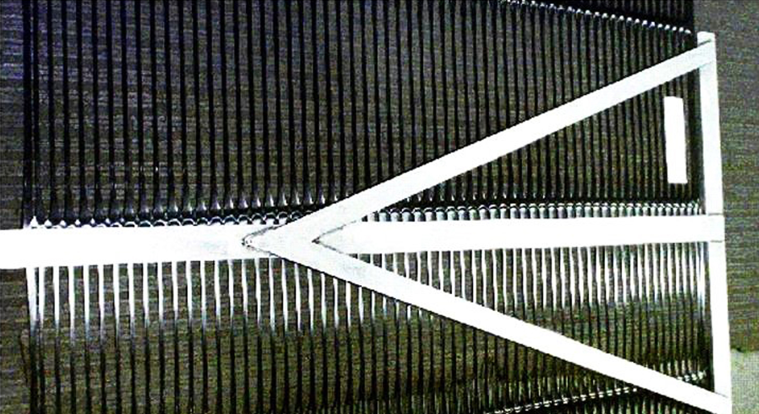
GRI Test Method GS-34, Standard Test Method for Determining Bow and Skew of a geosynthetic was announced on November 1, 2023. This test method is intended to determine conformance of a geosynthetic to bow and skew, which are geometric concerns of manufactured materials. When weft or cross-machine elements are even at two edges but arched across the middle, the defect is known as “bow.” Bowing is a condition in many geosynthetics where filling yarns or cross-machine elements are displaced from a line perpendicular to the selvages and lie in an arc across the width of the material. Bowing appears as rows of courses forming a bow-shaped curvature along the geosynthetic width, as shown in Figures 1a and 1b, where 1a is a photograph of a uniaxial geogrid and 1b is a schematic diagram of the property being measured.
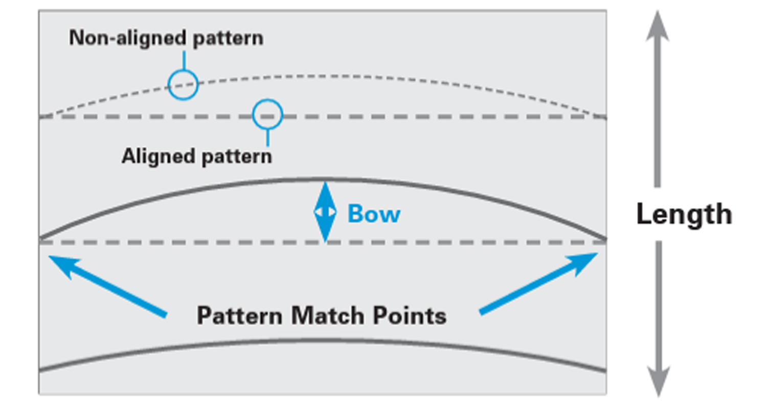
In this determination, a full width geosynthetic test specimen is placed on a flat surface. A straight edge is then set against the cross-machine rib or yarn touching both ends simultaneously. The bow is the measurement of length at the point where the transverse rib or yarn deviates farthest from the straight edge. One should measure the greatest distance between the perpendicular line and the yarn, stripe or dominant line at any point across the width of the material. The process/procedure should be repeated at least three times in places along the length of the material and then the maximum bow should be reported, along with the location of the occurrence. If this defect is not resolved, it may cause cutting, sewing/seaming and connection problems. It may also create serious problems during production like telescoping or wrinkling. There may also be an issue with residual bowing when the material is exposed to extreme environmental conditions in the field.
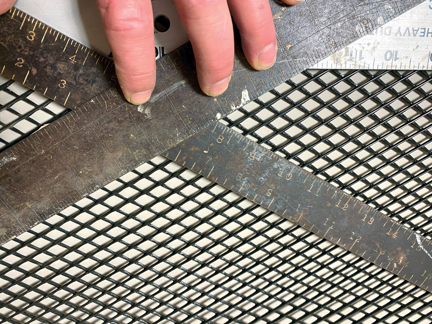
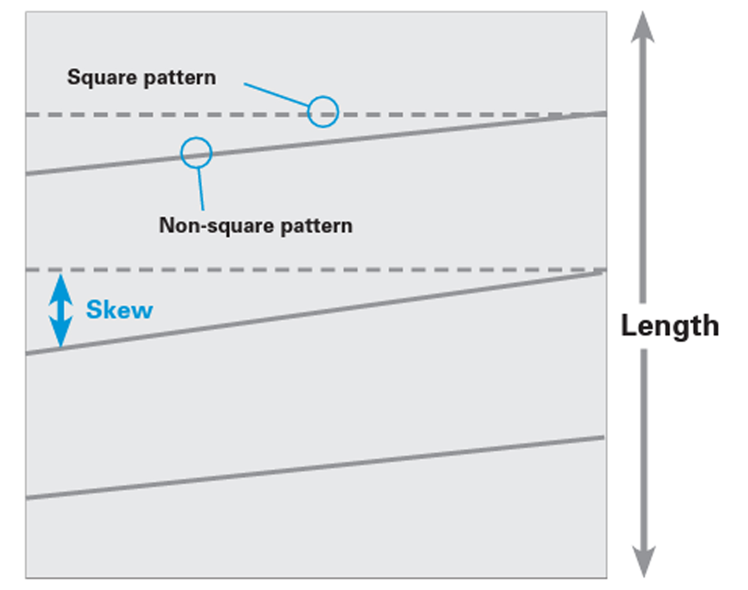
Skewing is a similar condition in which filling yarns or cross-machine elements are angularly displaced from a line perpendicular to the edge or side of the material due to uneven distribution of tension. Figure 2a is a photograph of a biaxial geonet where the “controlled” skew is intentional, and Figure 2b is a schematic diagram of the property being measured.
In the determination of skew, a full width geosynthetic test specimen is placed on a flat surface. One limb of a square is aligned along the machine direction of the center-most longitudinal rib or yarn. The lower tip of the opposite limb of the square is then brought into contact with a cross-machine rib or yarn. The skew is the measurement of length that the machine direction rib or yarn is out of square from the cross-machine direction rib or yarn measured at the inside elbow of the square. Distortion in the consistent construction of the material may constitute a defect. It is also interesting to note that the pattern on one side of the material may be different from or ahead of the pattern on the opposite side.
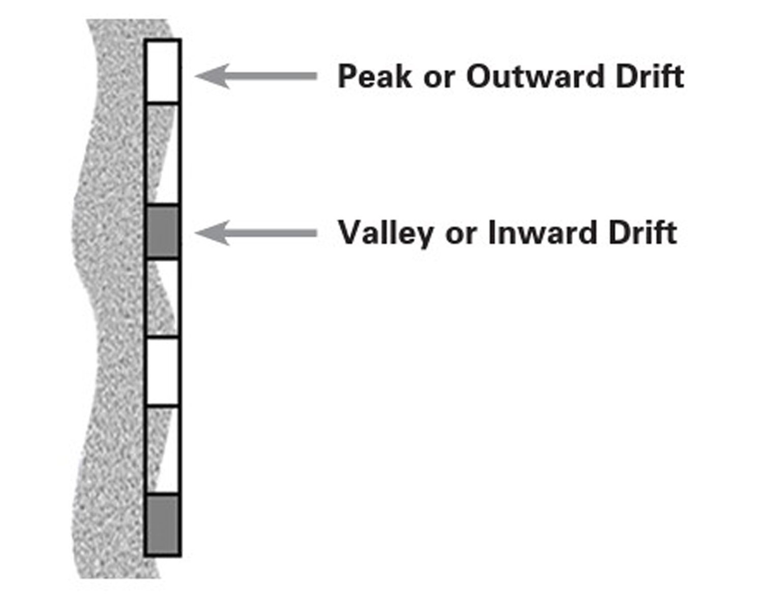
Another geometric property that was not mentioned in the new test method is “trueness of edge.” This term is used in relation to serpentine or snaked edges that are usually present in some degree on all geosynthetic rolls. Geosynthetic rolls that “drift” can often be corrected if each outward drift corresponds to an inward drift on the opposite side of the material width and if pulling one side of the geosynthetic to a straight line straightens the corresponding opposite side.
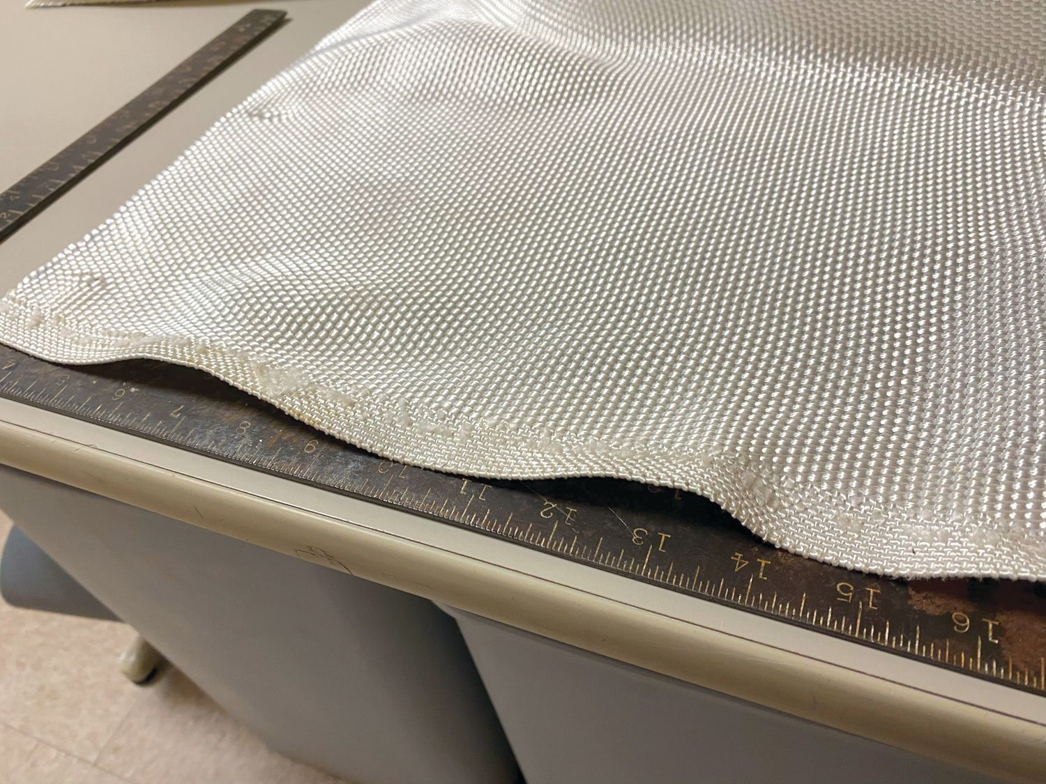
Trueness of edge is measured by pulling a straight line lengthwise down the roll from one corner to another or to a corresponding “peak,” as shown in Figures 3a and 3b, where 3a is a photograph of a woven and 3b is a schematic diagram of the property being measured. The distance of the “valley” from the straight line should establish the amount of drift. If the material suddenly moves inward or outward on one side without having a corresponding peak or valley on the opposite side, it is unlikely that stretching the affected area will correct the problem.
Bowing, skewing and trueness of edge in geosynthetic rolls usually occur during operations where there is a risk of uneven tension across the width. Needless to say, the lighter the material in mass per unit area, the more likely these conditions are present. As there are no industry standards for such variations, individual producers have developed their own manufacturing tolerances of these three conditions. Now, certified quality auditor (CQA) personnel have a standard way of measuring these conditions to hold manufacturers to tolerances pre-installation.
It is freely admitted that this new standard is a rudimentary attempt at measuring a few geometric manufacturing parameters. ASTM D3882, Standard Test Method for Bow and Skew in Woven and Knitted Fabrics, has been around since the 1940s and we know manufacturers have all sorts of in situ monitoring technologies to control their processes. However, by adhering to specifications and using products that meet GRI GS-34, field personnel can ensure that the geosynthetic will be consistent. Following such methods will help prevent common installation errors and material issues due to inconsistent manufacturing.