 TEXTILES.ORG

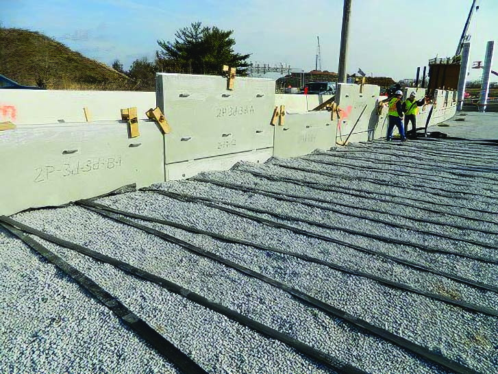
The Geosynthetic Institute (GSI) now has a revised test method for determining the tensile properties of geosynthetic straps. They are an extremely strong reinforcement element for mechanically stabilized structures. These soil reinforcing elements consist of high-strength extensible geosynthetic reinforcing straps that are connected through a sleeve or embedded connector to precast concrete facing panels. Such structures are ideal for construction in or near water and other aggressive environments. Geosynthetic strap reinforcements are suitable for mechanically stabilized structures such as walls, steep slopes and reinforced embankments. A typical retaining wall installation using geosynthetic straps is shown in Figure 1.
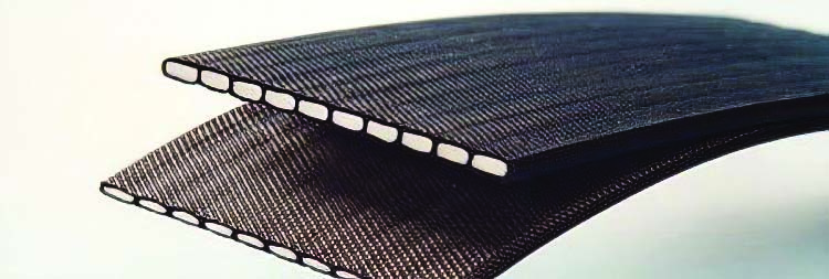
These reinforcement geosynthetics are typically 2 to 4 inch (51 to 102 mm) wide straps that consist of high-tenacity polyester fibers encased in a polyethylene jacket. A photograph of a typical geosynthetic strap is shown in Figure 2. The high-tenacity polyester is the load-bearing element, while the jacket protects the yarns from installation damage and degradation. They exhibit the following properties compared to geogrid or geotextile reinforcement:
- High-strength geosynthetic strap reinforcement exhibits less extensibility (strain at failure < 11%) than typical geogrid or geotextile reinforcement.
- Geosynthetic straps are suitable for highly aggressive and corrosive environmental conditions. The polyester yarns within the geosynthetic straps are comprised of high-tenacity polyester filament yarns with high tensile strength and modulus, low creep and high molecular weight (>25,000 g/mol) and carboxyl end groups (>30 mmol/kg) to ensure excellent performance and durability.
- Geosynthetic strap connections to precast facing panels are secure, simple, quick and easy.
- The composition and geometry of geosynthetic straps are dimensionally stable, weather resistant and resistant to installation damage.

GSI first published this standard method in 2019 and has recently updated it as GRI-GS21, Test Method for the Determination of Tensile Strength Properties of Geosynthetic Straps. This test method is intended for quality control and conformance testing of geosynthetic strips. However, the results can also be used for design. We felt that it was important to update it in advance of Robert Lozano’s (technical manager and senior geotechnical engineer with The Reinforced Earth Company) effort within ASTM D35, the Subcommittee on Geosynthetic Product Specification. It will be a nice counterpoint for lessons learned and round-robin data.
In determining the tensile strength of various geosynthetic straps, there are numerous difficulties in clamping and testing representative samples due to their thickness, width, coating, stiffness and varying forms of construction. The GRI GS-21 method performs tensile tests on representative specimens to determine their strength. The results of these tests can be used to calculate the ultimate strength and corresponding strain of the geosynthetic strap in the direction of the test. It should be noted that most geosynthetic straps have a single principal direction.
This test method is applicable to all types of geosynthetic straps. Some modifications of clamping techniques may be necessary for a given geosynthetic strap depending upon its construction. The test apparatus for this method consists of three parts: the tensile testing machine, clamps and extensometer. The tensile testing machine should operate under a constant rate of extension (CRE). It should have a load cell capable of measuring 10% to 90% of the ultimate tensile force of the material being tested. An entire force versus elongation curve needs to be recorded during the test. The constant rate of extension apparatus should conform to ASTM D76, Standard Specification for Tensile Testing Machines for Textiles, and ASTM E4, Standard Practices for Force Calibration and Verification of Testing Machines.
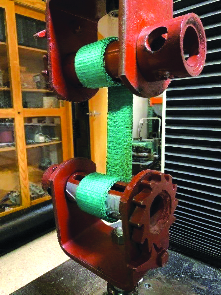
Testing clamps shall be sufficiently wide to grip the entire geosynthetic strap and with appropriate clamping power to prevent slipping or crushing. Special clamping configurations may be necessary for geosynthetic straps constructed of coated fibers or yarns to prevent them from damage as a result of being gripped too tightly in the clamps. The suggested clamps are shown in Figures 3 and 4. When testing geosynthetic straps with roller grips, it is often difficult to achieve centerline to centerline grip separation and plumb. For this reason, a universal or swivel joint is recommended for attachment to one of the clamps to eliminate any eccentricity in the setup.

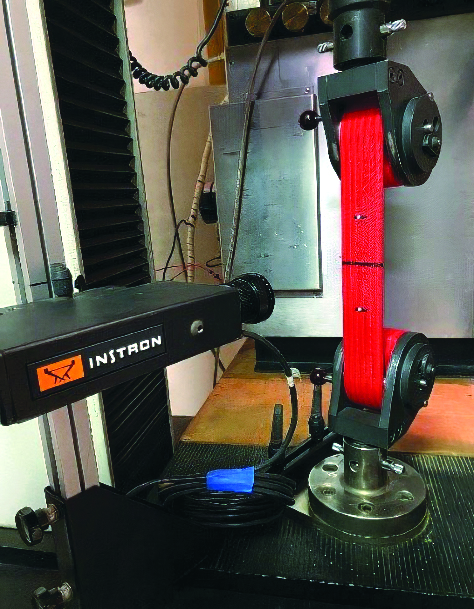
Since the grips in most cases will be roller or Capstone-style clamps, an extensometer will be needed to monitor deflection throughout the test. These devices can be a contact or noncontact extensometer, as shown in Figures 5 and 6 respectively. Note that strains below 10% are required to be monitored precisely.
Procedure for Testing
The load cell and extensometer need to be calibrated prior to mounting the geosynthetic strap in the clamps. Then, the CRE needs to be balanced after the clamps have been mounted. Prepare for testing by mounting the specimen centrally in the clamps and tighten sufficiently to prevent damage to the specimen. A 1% preload is allowed to remove any slack from the setup. Next, set the constant rate of extension of the test machine to 10%/min. Initiate the test by starting the testing machine and continue running the test until rupture occurs. Record and report the entire force versus elongation response up to and including failure.
Repeat the above procedure until 10 acceptable breaks have been obtained. The specimen result should be discarded and another test run if:
- Specimen slips in the clamps
- Specimen breaks at the edge
- Specimen breaks within the clamps
- Faulty operation occurs
- Result falls markedly below the average for the set of specimens
Report
From the test data, a force-elongation curve for each test with a description of the type of failure that occurred should be presented. On each of these curves, the ultimate strength and corresponding strain should be indicated. In addition, modulus at specific strain level may be requested (i.e., 1%, 2%, 5% and 7%). The report should also include the number of tests performed, the rate of extension and the type of clamps utilized.