 TEXTILES.ORG

Polyethylene (PE) seaming techniques are used in the field to fabricate rolls of geomembranes into liner systems. There are two predominant methods used: hot wedge “fusion” welding and “extrusion” seaming. Over the past year, installers have noticed lower trial weld strength than in years past. This makes for much discussion on the jobsite between certified quality auditor (CQA) personnel and installers. No one wants to be below the GRI-GM19 specification for seam strength at the start of a job. This article presents one rational for lower peel and shear strength as a result of reduced thickness of a welding edge. Specification thinning in the area to be bonded can compromise seam strength. Obviously, this needs to be checked and reconciled prior to job commencement.
The hot wedge method of seaming PE consists of a hot electrically heated element in the shape of a wedge that is passed between the two sheets to be bonded. Contacting the two heated surfaces together causes a fusion of fresh material to create a weld. Immediately following the melting, roller pressure brings the molten surfaces together to form a homogeneous fused bond. Single hot wedge and dual hot wedge systems are both available. The dual hot wedge weld forms a continuous air channel between two welds. The air channel can be used as a means of testing the bond continuity when air pressure is injected into it. Fusion welding parameters include speed rate, temperature and roller pressure. Most modern welders can continuously control, monitor and record these parameters. Adjustments are made according to environmental conditions such as ambient temperatures and relative humidity.
Extrusion welding is commonly used for PE geomembrane repairs and around appurtenances. The extrusion welding process starts by hot air tack welding the overlap. This blows away debris from the area to be welded. Directly following the hot air tack weld, the area of the geomembrane to be bonded is buffed, cleaned and beveled with a handheld grinder. Finally, a ribbon of molten polymer (the same composition as the geomembrane being seamed) is extruded onto the prepared ground surface by a handheld extruder. This fillet bead of the molten polymer is placed at the edge of the overlap where the two geomembranes are being seamed.
The seams described above are tested via ASTM D6392, “Determining the Integrity of nonreinforced Geomembrane Seams produced using Thermo-fusion Method” in the field as startup weld and destructively as quality control and quality assurance tests to determine the integrity of geomembrane seams produced. ASTM D6392 presents the procedures used for determining the quality of bonded seams subjected to both peel and shear tests. In both cases, seams are evaluated for strength, ductility and the type of failure. It should be clearly stated that a seam needs to exceed all three characteristics to pass the GRI-GM19 specification.
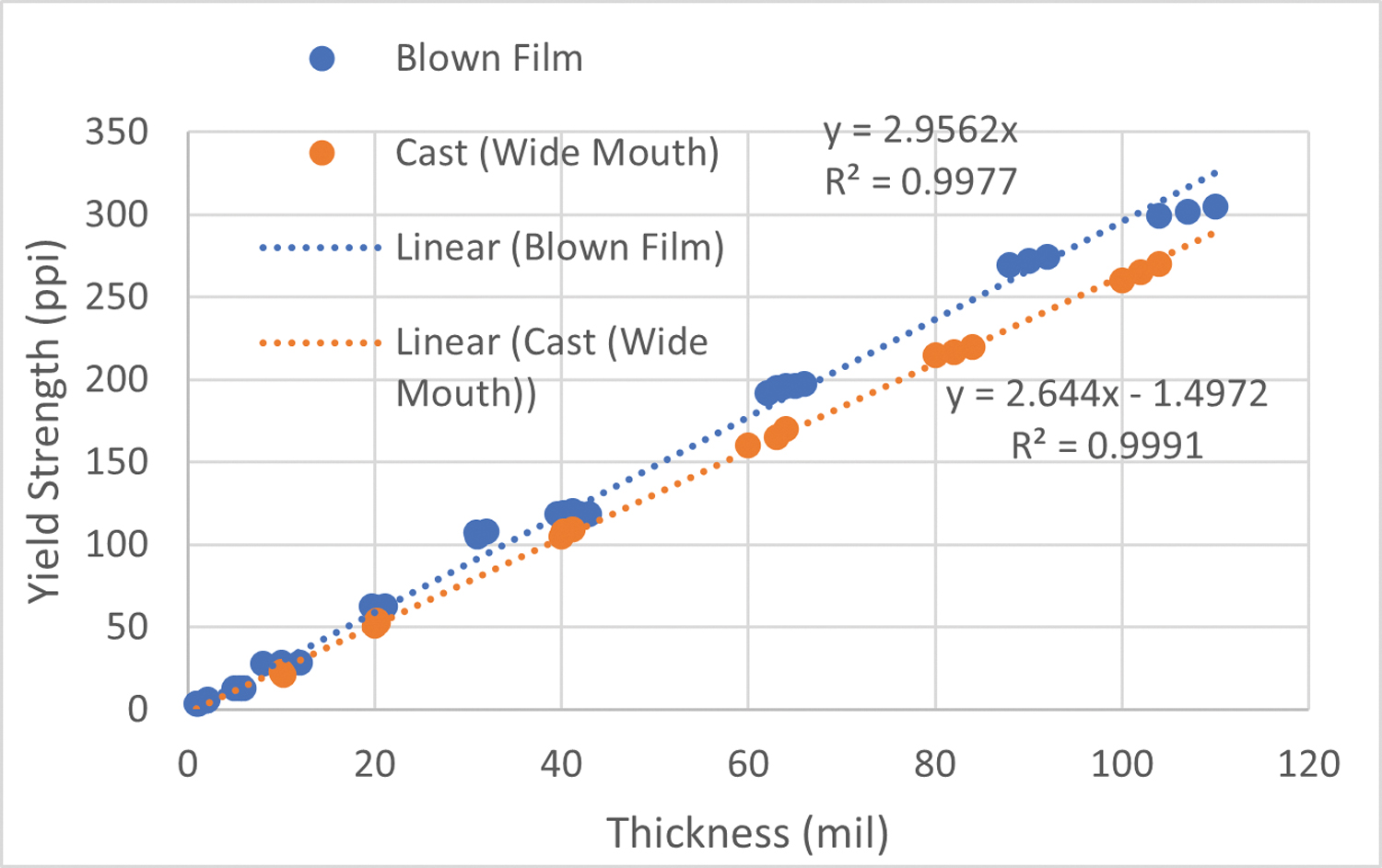
An observation that will have direct consequences of seam strength is parent material thickness. As can be seen from Figure 1, thickness is linearly proportional to yield strength in PE. Therefore, if the material is thin, it will be difficult to meet specifications assuming a film-tear-bond (FTB) response where the seamed geomembrane breaks in the parent material rather than within the seam.
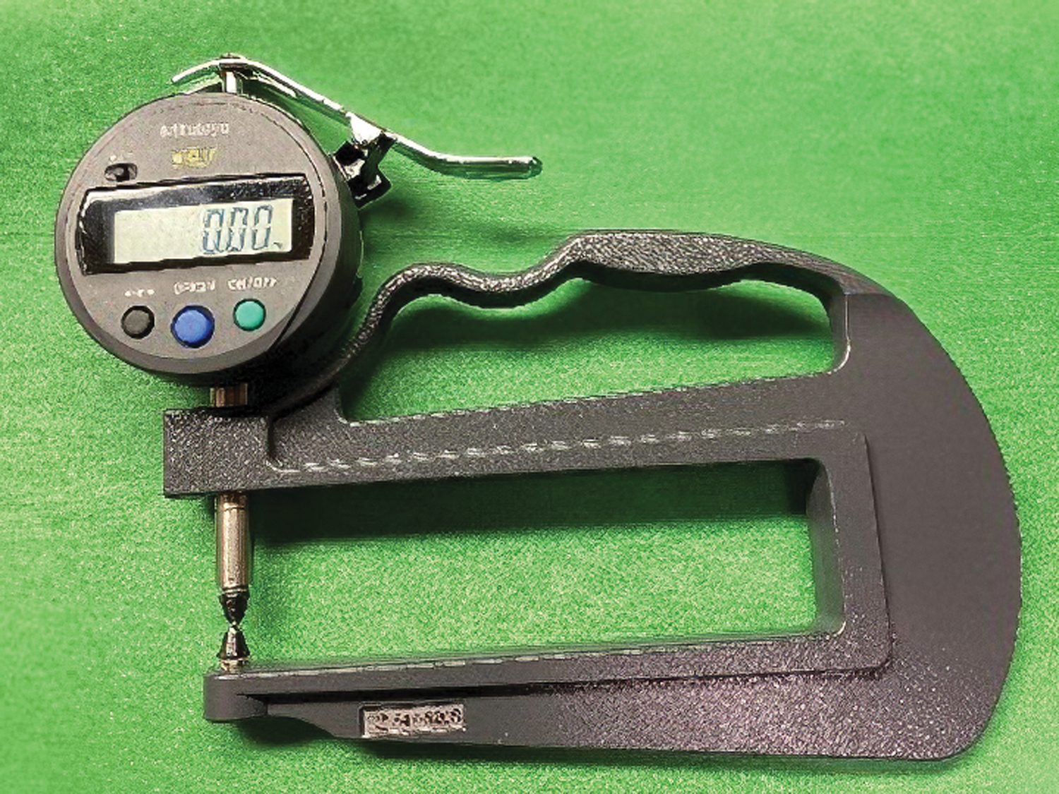
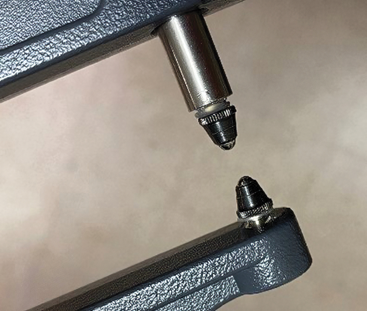
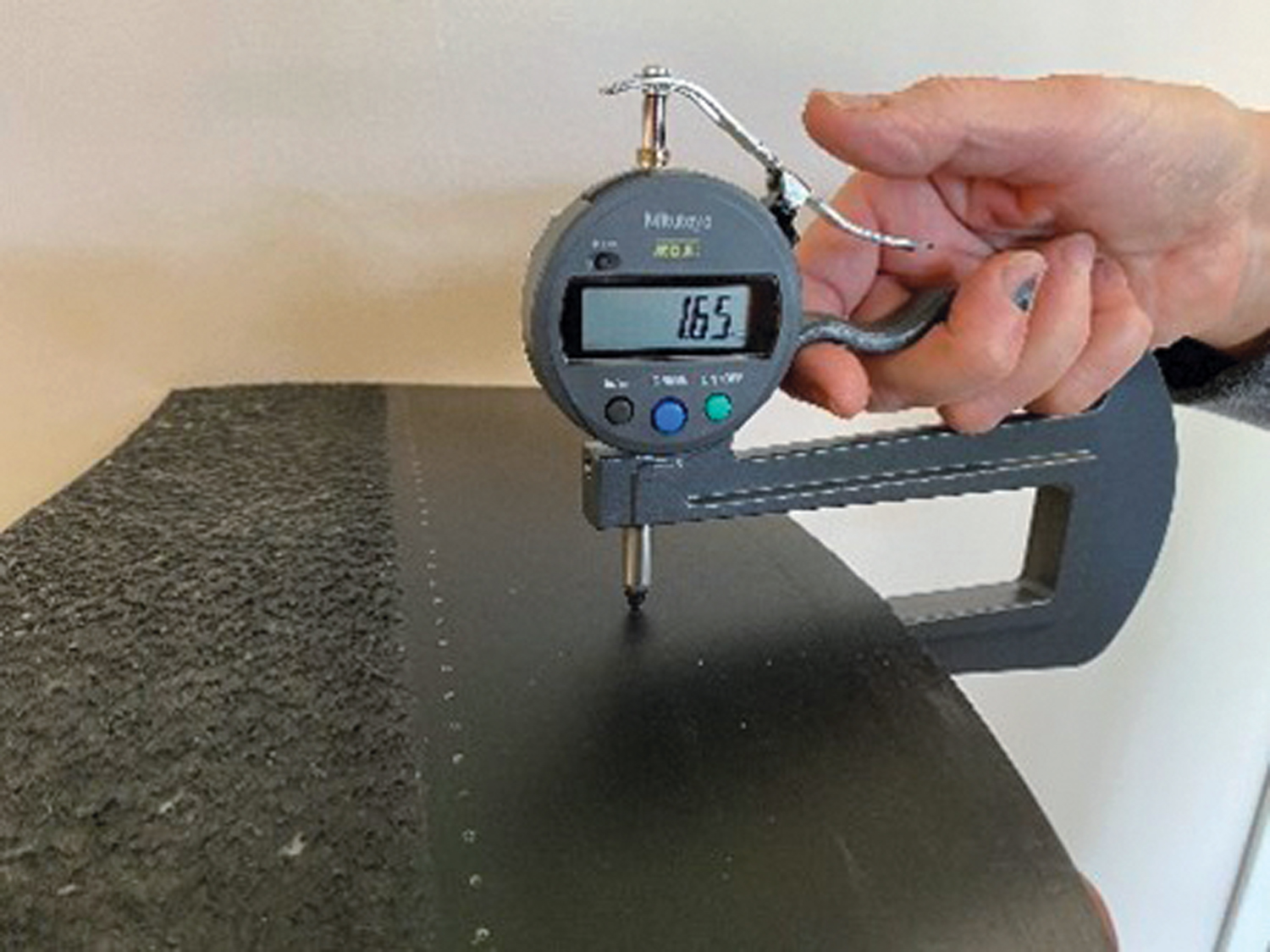
The Geosynthetic Institute (GSI) has a new test method to check for this inconsistency. GRI-GM37 standard test method for Determining the Weld Edge Thickness of Geomembrane has just been adopted. This nondestructive test method covers the direct measurement of the thickness of the weld edge of geomembranes. The thickness of a weld edge is observed as a direct read from a handheld thickness gauge used as a planimeter, as shown in Figures 2a, b and c. The measured thickness of the geomembrane weld edge may vary considerably depending on how it was fabricated. To reduce variation and improve quality, thickness thresholds are now regularly set in specifications to limit excessively thin material at the weld edge.
Traditionally, seams have been tested and assessed on the basis of shear and peel strengths. It is acknowledged that there is a stress concentration adjacent to the seam, and it can be a very complicated stress state at the intersection. However, the strength and integrity of the seam is paramount to a successful job.
A concluding thought when considering the thickness of the geomembranes being welded: the actual weld interface area is the same and the expectations of weld strength should be the same. Yet, when we specify shear and peel strengths, the specified strengths increase with thickness. Does this mean we are expecting better bonding in thicker geomembranes? If we are welding the same materials with the same interface area, we should be achieving the same weld properties independent of thickness. In specifying higher strengths for thicker materials, we are simply measuring the strengths of the geomembrane itself. In no way are we assessing the weld integrity to any significant extent. Please realize this is only one parameter that the installers are striving to control.