TEXTILES.ORG

Nearly all geomembrane installations are fixed at the perimeter of the containment by burying the liner in an anchor trench or by attaching it to concrete (i.e., a collar wall, foundation, ring wall, manhole, vault, etc.). The standard approach for connecting the geomembrane liner to concrete is to use anchor bolt geomembrane connections with batten strip or Rondel connections, as described in ASTM D6497, “Standard Guide for Mechanical Attachment of Geomembranes to Penetrations or Structures.” For polyolefin (PE and PP) geomembranes, Rondels or embedment strips are the preferred methods of attachment for the following reasons.
Speed of installation: Welding to an embedment strip can reduce the time it takes to attach a liner to concrete.
Cost reduction: Stainless steel batten and anchors are expensive and labor intensive to install and maintain.
Application Flexibility: Embedment strips have been used in both horizontal and vertical applications which provide positive fixity with more even stress distribution between the geomembrane and the structure.
Installation quality: It’s important that the embedment strip be affixed to the forms so that it remains level or plumb and has a good end-to-end (butt) connection, which is welded. The point at which the ends of the strips touch must be welded to ensure containment.
Thermal expansion/contraction considerations: Materials have different coefficients of thermal expansion and contraction properties. This may present additional considerations during construction and long-term use for geomembrane connections. Embedment Rondels have shown excellent long-term performance in changing environment conditions, requiring little or no maintenance over time.
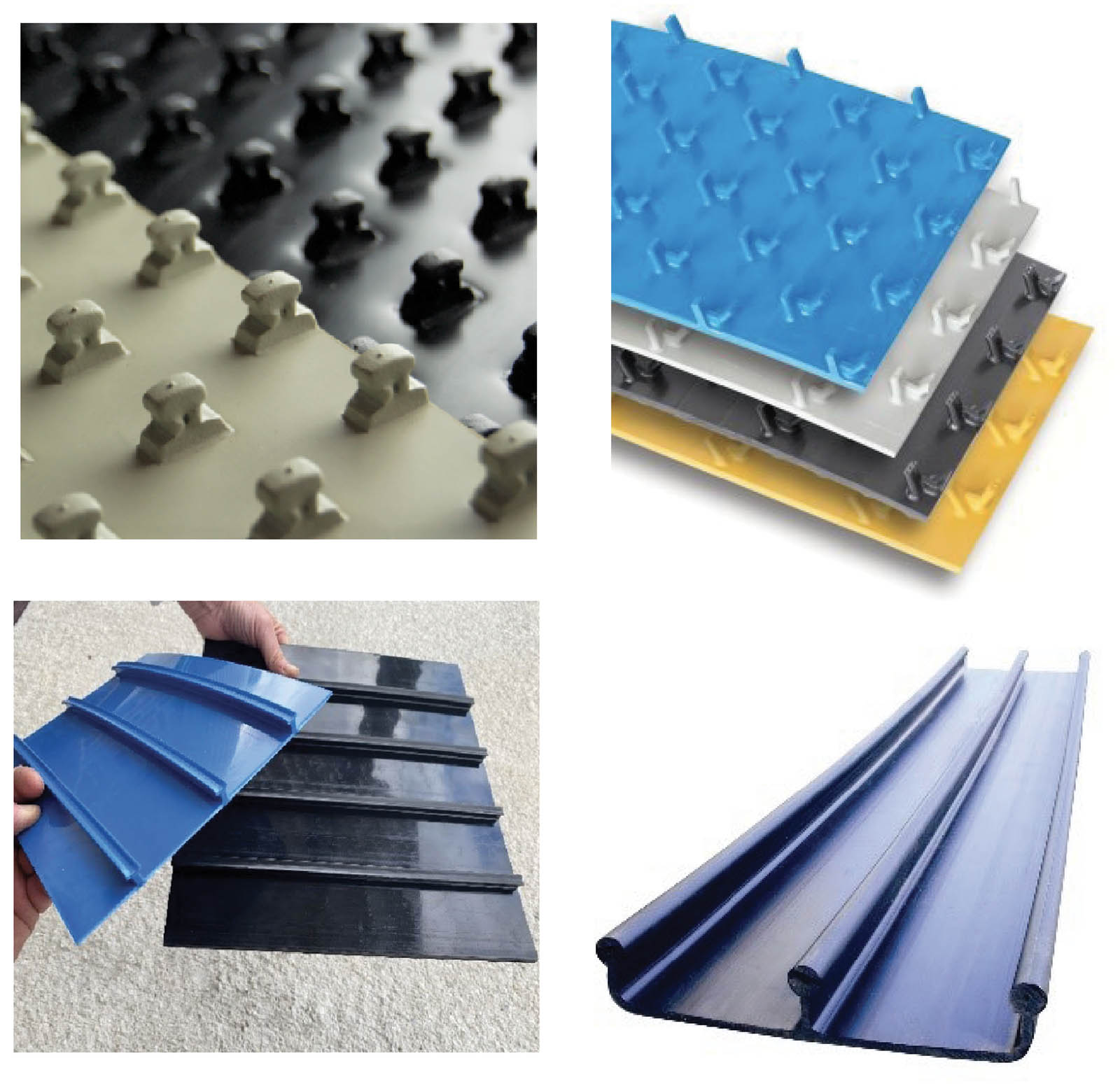
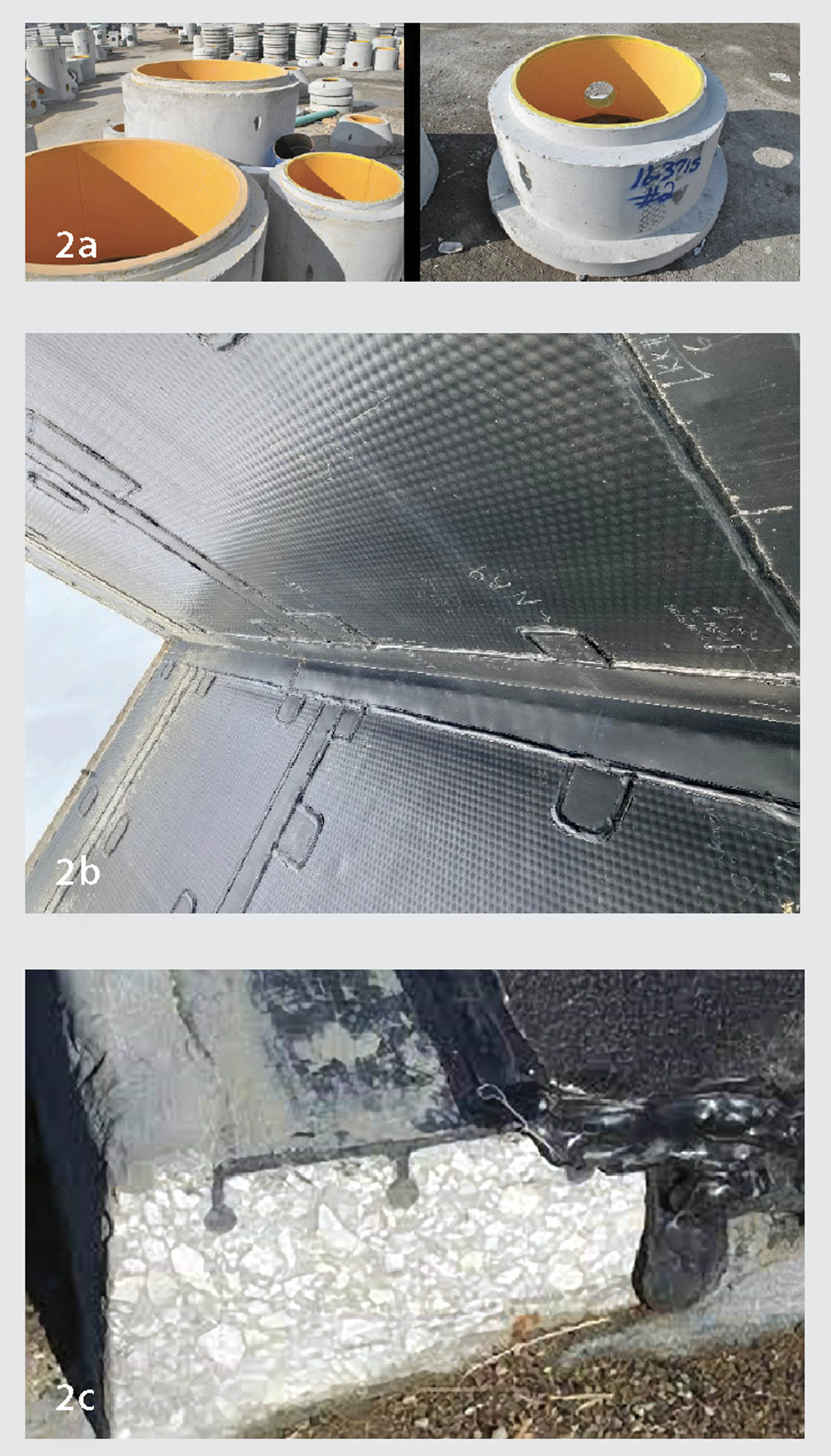
Embedment high-density polyethylene (HDPE) liner is often used for concrete protection. Studs in these geomembranes create a product with exceptional pullout strength and high resistance to mechanical, chemical and environmental threats. Such embedment liners (Figure 1) can be used in a wide range of civil applications (Figure 2). To date, there has not been a standard test method to determine the design strength for such systems. This has changed with the advent of the Geosynthetic Research Institute (GRI) Method GS-31, Standard Test Method for “Measuring the Connection Strength of Geosynthetic to Concrete or Mortar.”
The objective of this test method is to determine the strength (capacity) of the connection between the geosynthetics and concrete or mortar in the laboratory. Such mechanical connection tests are performed in tension to verify that the design load can be adequately transferred from the geosynthetic to the cured pozzolanic material.
This GRI-GS-31 standard method covers two different procedures: procedure A, where the geomembrane is pulled with the concrete anchored; and procedure B, where the concrete is pulled and the geomembrane is fixed. Both procedures determine the load-deformation behavior of the geosynthetic connection system to provide the engineer with data to judge the adequacy of adhesion of the two-component system.
Procedure A concrete stationary with embedment liner in motion
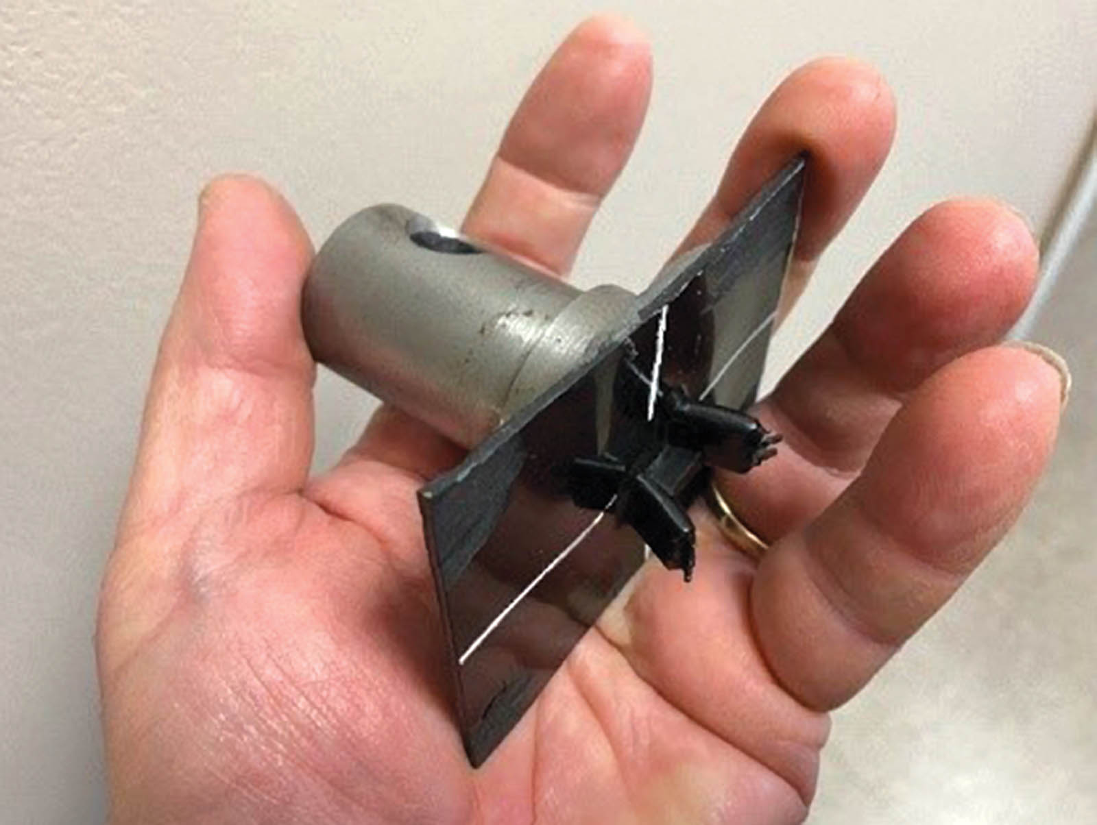
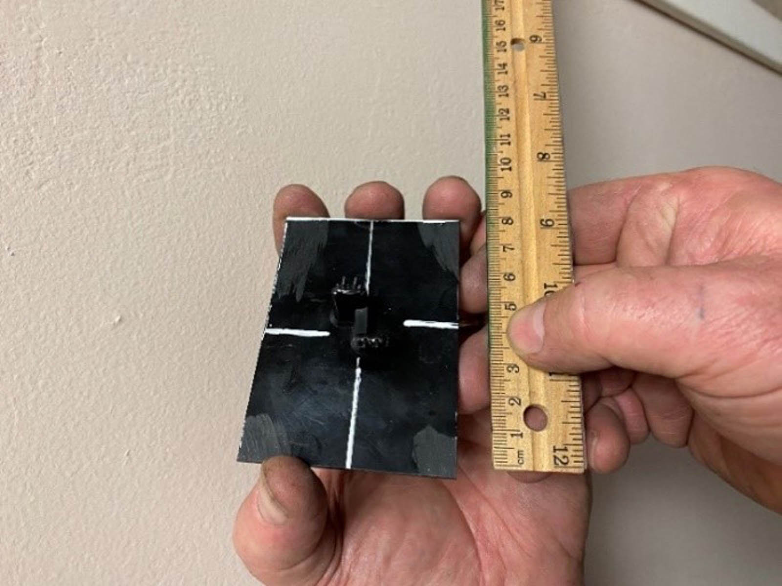
Reinforced cubes of concrete are cast and then a piece of embedment liner is inserted into the wet mortar. Typically, a 2.3 inch × 3.3 inch (60 mm × 85 mm) specimen with one centrally located stud (one inclusion) of the embedment liner are prepared, as shown in Figure 3.
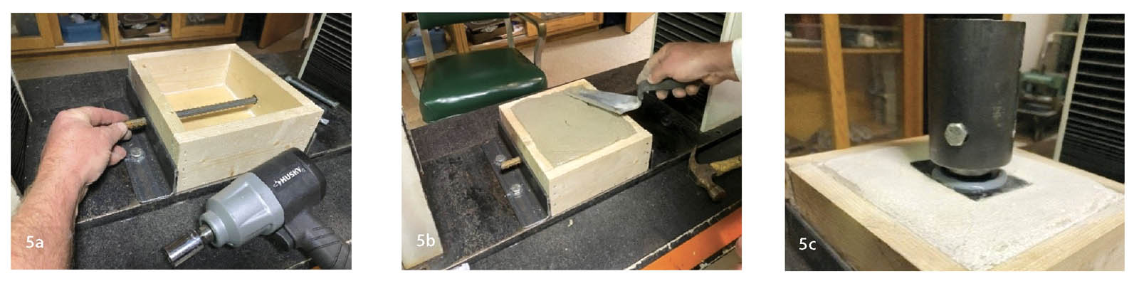
These specimens need to be adhered to a mounting post (Figure 4). This technique can be done in several ways depending on resources. Please note, the mounting needs to be stiff and much stronger than the bond of the embedment liner to the concrete.
The specimen is then pushed into the wet concrete and allowed to cure at lab temperature for the allotted 1, 7 or 28 days. This is best done within a humidity-controlled chamber. This technique is shown in Figure 5.
Procedure B embedment liner stationary concrete in motion
Most commonly, cylindrical test specimens are cast on top of the embedment liner for procedure B. The cylindrical mold needs to be lubricated with grease acting as a mold release. The mold is then glued to the embedment liner so that mix water from the concrete cannot leak out of the sealed mold.
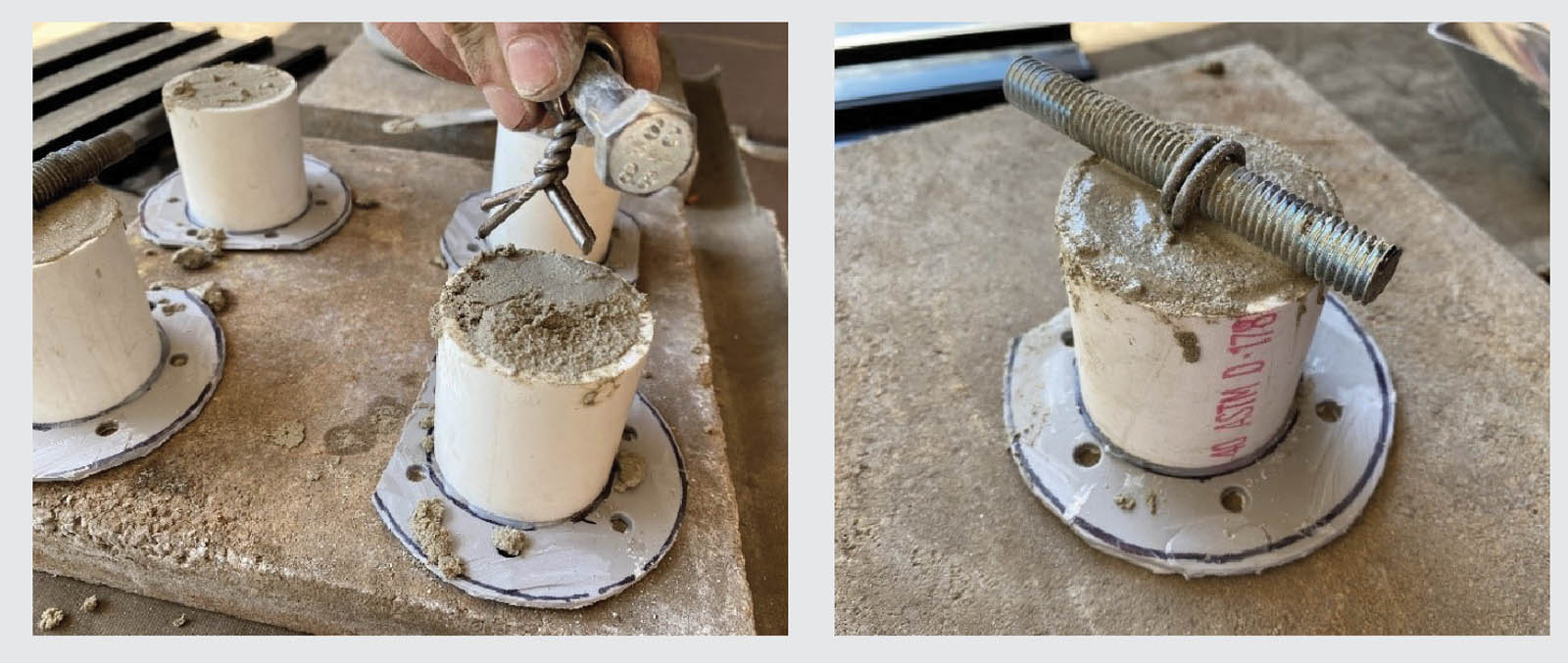
The concrete is placed in layers into the molds and consolidated using vibration and rodding. While the concrete is still wet, steel anchor eyelets are inserted into the top of the fresh concrete cylinder (Figure 6). Note that the eyelet assembly will need to be stronger than the connection strength of the embedment liners to the concrete or mortar.
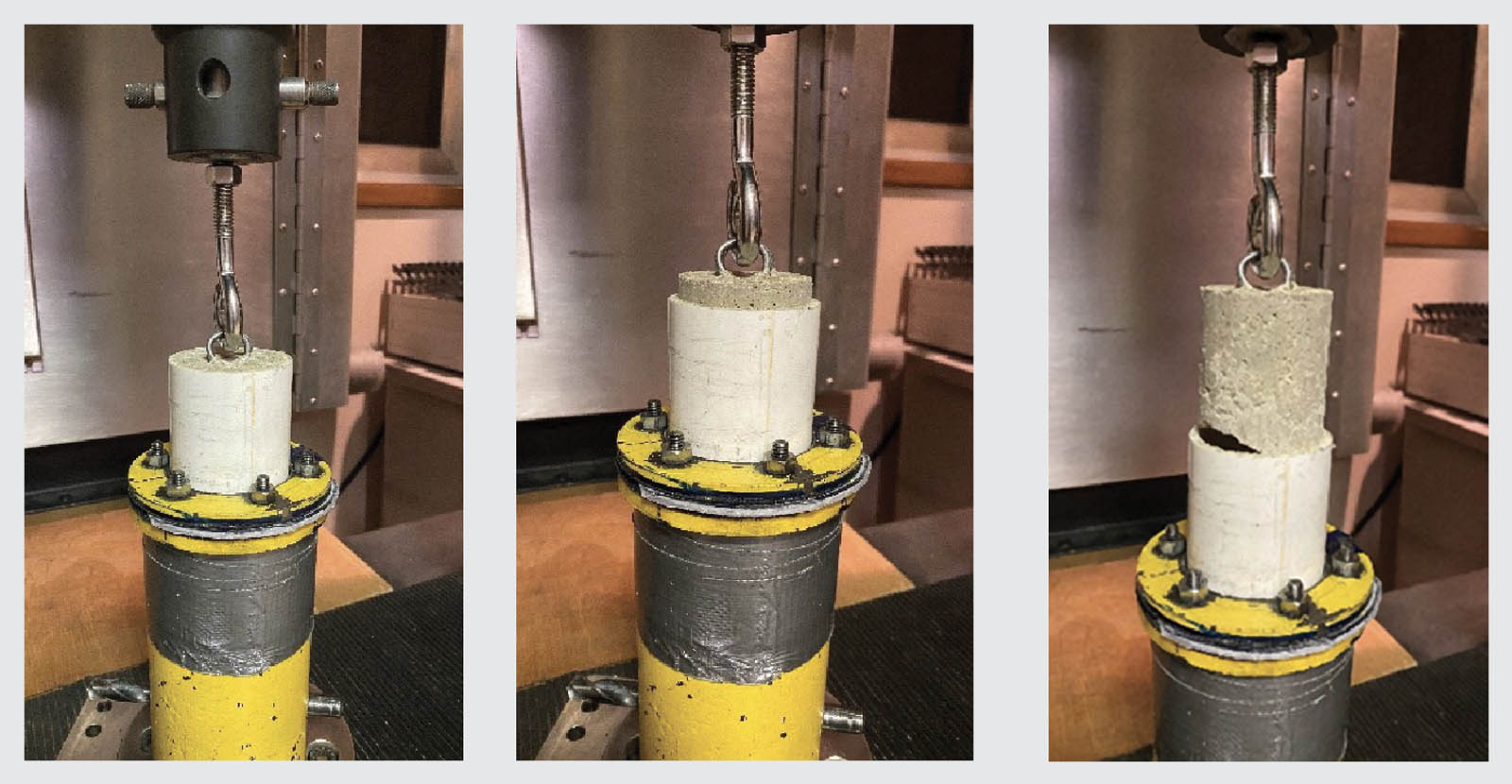
The specimens are then finished and transported to a temperature- and humidity-controlled chamber for curing. After the specimens have cured, they are affixed to the testing fixture within a constant rate of extension (CRE) machine. Unless otherwise specified, apply the load smoothly at a rate of 0.2 inches/minute (5 mm/minute) for the duration of the test. A sequence of photographs showing the test in progress appears in Figure 7.
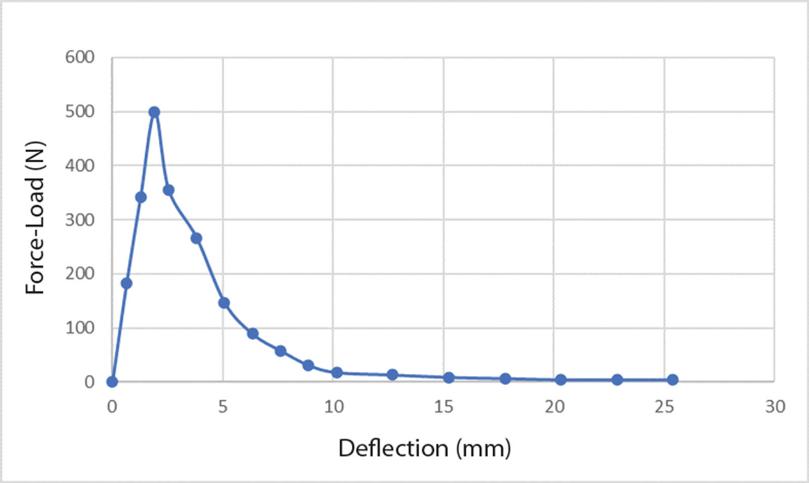
Once the test is complete, the displacements and corresponding loads are recorded. Typical results are shown in Figure 8, for either procedure A or B.
In summary, we feel that there now exists a new tool to evaluate embedment geomembranes. It allows us to explore different stud styles and configurations as well as different mix designs. It does not proport to simulate full field conditions of embedment liners or the group effect of multiple studs or configurations. However, this method is a first step in conformance testing to a specification or establishment of saturated process control (SPC) database for materials used in such applications.