 TEXTILES.ORG


The project presented herein was designed to enhance an existing groundwater drainage system and repair erosion related to groundwater seepage on a berm constructed using coal combustion residuals (CCR) on top of a Lake Michigan bluff at a site in southeastern Wisconsin. This article presents the planning, design and implementation of the remedy. The planning and initial design for permitting began in the fall of 2013. Confirmation of the initial design, including laboratory testing with site soils and the geosynthetics products used in the installation, and installation of the remedy, was completed in the summer of 2014. Relocation of a portion of the CCR berm occurred in 2018.
The groundwater drainage system was designed to consist of a geocomposite drainage layer buried in the side slope of the berm, extending up from the elevation of the existing drainage trench to an elevation above observed groundwater seepage and associated erosion. The geocomposite drainage layer was designed to extend laterally throughout the erosion area and tie into a manhole and downslope conveyance pipe.
Erosion repair measures consisted of grading/filling rills and the reestablish-ment of vegetation, including topsoil, seeding and an erosion control mat.
In the 1960s berms were constructed around the perimeter of the site using CCR. When originally constructed, the berms were 60-feet (18-m) high with side slopes of 1.5H:1V. It was reported that more than 1 million tons (910,000 tonnes) of CCR were placed on the site, with the majority going into the perimeter berms. The CCR were covered with soil 24 inches (60 cm) in thickness to establish vegetation and were seeded.
In the late 1990s the slope of the berm along Lake Michigan was reduced from 1.5H:1V to 2.5H:1V to address stability concerns. It extended 360 feet (110 m) up from the Lake Michigan shoreline, a long slope presenting a significant erosion-control challenge. A groundwater collection trench was also constructed parallel to the slope contours.
However, the collection trench was constructed in the bluff soils below the interface between the bottom of the CCR berm and the top of the native lake bluff soils, below where most of the seepage was occurring. Seepage upslope of the collection trench eventually caused softening of the surface soils and significant raveling of the slope, as shown in Figure 1.
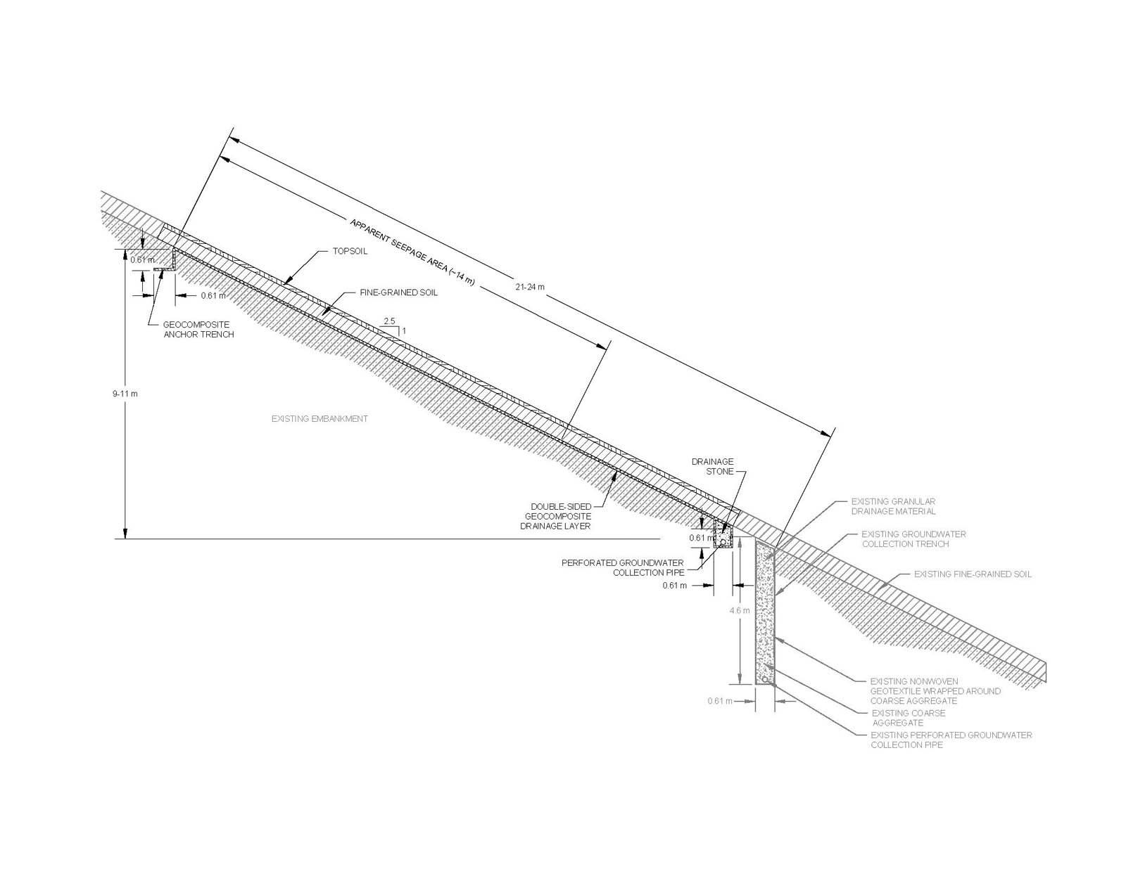
A geocomposite groundwater drainage system was designed to address the groundwater seepage occurring upslope of the existing groundwater collection trench and the resulting surficial erosion by collecting the groundwater in a geocomposite drainage layer buried 30 inches (76 cm) below the ground surface to prevent saturation of the surficial soils. Saturation of the surficial soils due to groundwater seepage likely inhibited vegetation establishment and promoted erodible conditions. The area of the geocomposite groundwater drainage system was determined based on the lateral extent of the erosion and the potential maximum groundwater elevation within the berm. The lower elevation of the geocomposite groundwater drainage system was positioned below the interface of the CCR and natural lake bluff soils, and above the previously installed groundwater-collection trench. The proposed profile of material within the area of the geocomposite groundwater drainage system consists of the following parallel layers, listed from the top down:
- Topsoil
- Fine-grained soil
- Double-sided geocomposite
- Coal combustion residuals (CCR)
A typical cross section of the groundwater drainage system is shown in Figure 2.
Construction of the geocomposite groundwater drainage system included stripping and stockpiling surface soils (topsoil and fine-grained soil), installation of a geocomposite drainage layer, groundwater collection and conveyance pipe, and a manhole. The geocomposite component of the groundwater drainage system was buried below the surficial soils to intercept and direct the captured groundwater by gravity to a drainage pipe for controlled discharge. Perforated high-density polyethylene (HDPE) collection pipes were installed in a trench at the downslope end of the geocomposite and backfilled with clean coarse aggregate. Cleanout risers were installed at each end of the collection pipes to provide access for maintenance and inspection. The collection pipes connect to a centrally located manhole, and groundwater is conveyed downslope from the manhole to Lake Michigan through a solid-wall HDPE pipe. Areas disturbed during construction and the erosion rills downslope of the geocomposite groundwater drainage system were restored by regrading the slope, seeding and installing an erosion control mat.
The efforts described herein were taken to address the seepage and provide increased surficial slope stability.
Field reconnaissance
Site-specific data were collected to support the design effort. Site visits included performing a topographic survey, televising the existing groundwater drainage system installed in the late 1990s, performing fine-grained soil-thickness checks, collecting representative soil samples and using photo documentation.
A ground survey was performed to prepare figures and cost estimates for the project. In particular, construction plans were developed and construction quantities were estimated. Ground-surface elevations were collected throughout the area with adequate resolution to quantify the soil balance for the fine-grained soil and downslope erosion rills. Elevations of surface-water drainage features were collected on the other side of the berm, including drainage ditch profiles and sections, and invert elevations of culverts and drainage pipes to better understand surface drainage conditions at the site and their contribution to groundwater seepage on the side of the berm facing Lake Michigan.
During the ground survey, the existing groundwater drainage system pipe was inspected by televising the collection and conveyance pipes. Access to these pipes was limited to a 15-foot (4.6-m) deep groundwater collection manhole, located on the slope of the berm 200 feet (60 m) from the top of the slope. The televising crew staged the support equipment at the top of the slope and ran the camera and cables down to the manhole. The crew was able to avoid confined space entry by using a rod with an elbow to insert and retrieve the camera while working from the ground surface.
Televising the existing groundwater drainage system revealed the downslope conveyance pipe was crushed to less than half its diameter about halfway down the slope (75 feet [23 m] from the manhole). It appeared that water was still able to pass, but the camera was unable to navigate that small of an opening. Using the camera-locating device, the pipe televising crew indicated the downslope conveyance pipe was buried 6 feet (1.8 m) below the ground surface.
The segment of collection piping running north from the existing manhole was completely blocked by soil, including stone of 1- to 2-inch (2.5- to 5-cm) diameter, 12 inches (30 cm) into the pipe from the manhole. Likely sources of the soil and stone in the pipe include pipe collapse or maintenance measures directing surface water into the top of the manhole. Pipe jetting was not feasible due to the limited access to the manhole (the closest access point was 200 feet [60 m] upslope of the manhole).
The segment of collection pipe running south from the manhole had a vertical sag 3 feet (1 m) into the pipe from the manhole that the camera was not able to navigate past. The southern collection pipe appeared to be free of the soil and stone; however, very little pipe length could be inspected. Smaller camera equipment is available that could potentially be used to complete the inspection of this segment, but access limited the implementation of this equipment.
Test pits were completed on a 50-foot (15-m) grid to confirm the thickness of the fine-grained soils over the CCR. This information was used to estimate quantities of on-site soils available for the project. Soil samples needed for transmissivity and direct shear testing of the geocomposite were also collected.
Design
Initially, the design under consideration utilized the collection manhole and conveyance pipe associated with the existing groundwater drainage system; however, data collected during field reconnaissance altered the originally conceived approach. Specifically, the depth of the existing collection manhole presented construction challenges, and the condition of the conveyance pipe required its replacement. Therefore, the approach was changed to design an independent groundwater drainage system upslope of the existing groundwater collection trench and leave the existing system unaltered.
The required capacity of the geo-composite drainage layer and collection pipe accounted for potential groundwater seepage rates and infiltration through the fine-grained soils overlaying the geocomposite, as well as reduction factors for long-term performance. The required interface friction between the geocomposite and surrounding soil was assessed using published values and a minimum factor of safety for veneer stability of 1.5. Interface friction and transmissivity values of the geocomposite selected for use in the project were later verified by laboratory testing.
Geocomposite transmissivity
To maintain the stability of the slope, the drainage layer must be adequate to prevent the development of seepage forces, mainly due to groundwater in this application. The long-term soil stability of the proposed slope configuration includes a geotextile/geonet drainage composite (geocomposite) designed to convey groundwater to a pipe network that ultimately discharges to Lake Michigan through a manhole and downslope conveyance pipe.
Darcy’s formula was used for estimating flow due to infiltration of water from the ground surface and for groundwater seepage collected by the geocomposite. Darcy’s formula assumes saturated conditions and laminar flow. The required transmissivity of the geocomposite, θreq, was estimated from Equation 1:
 Where,
k = hydraulic conductivity of the CCR and fine-grained soil
L = geocomposite length
β = maximum slope of the berm, degrees
The maximum design slope length of the geocomposite was 80 feet (24 m) on the 2.5H:1V slope. The hydraulic conductivity, k, was estimated using Equation 2 and applying data from a historical subsurface investigation and field observations:
k = Ki (2)
Where,
K = the soil permeability
i = hydraulic gradient
Records indicated most of the berms were constructed using fly ash, but bottom ash was also present. Therefore, the permeability of the CCR material, Kccr, was estimated to be 5 × 10⁻⁴ cm/sec based on a combination of fly ash and bottom ash (Schroeder et al. 1994). The overlying fine-grained soil permeability, Kfg, was estimated to be 5 × 10⁻⁵ cm/sec.
Documentation provided results of a subsurface investigation program conducted in October 1993 (prior to grading of the east berm to 2.5H:1V) to generally characterize the CCR comprising the east berm. Borings were drilled along the highest portion of the berm and groundwater elevations were reported on the boring logs at 663 feet (202 m) National Geodetic Vertical Datum of 1929 (NGVD 29).
The lowest seepage area on the slope, based upon visual inspections completed in 2013, was at an elevation of 650 feet (198 m) (NGVD 29), 210 feet (64 m) east and downslope of the boring locations, as determined from aerial photos. Additionally, the ground surface elevation at the toe of the other side of the berm was 669 feet (204 m) (NGVD 29). Groundwater hydraulic gradients, igw, were estimated based on the limited historic data, and a conservative estimate of 0.064 was selected for the design. The fine-grained soil overlying the geocomposite was conservatively assumed to be saturated; therefore, a vertical seepage gradient was considered for the fine-grained soil (ifg = 1).
The long-term in-soil transmissivity of the geocomposite, θLTIS, was then determined by applying a series of reduction factors to the required transmissivity (based on assumed inflow). The reduction factors account for geotextile intrusion, geonet creep, chemical clogging and biological clogging, as described in Equation 3:
![]()
Where,
RFin = reduction factor for geotextile intrusion, beyond 100-hour seating time into the geonet core, resulting from time-dependent deformation of the geotextile
RFcr = reduction factor for geonet creep under the sustained compressive load
RFcc = reduction factor for chemical clogging
RFbc = reduction factor for biological clogging
The highest reduction factor for geotextile intrusion recommended by Giroud et al. (2000), 1.2, was applied, considering transmissivity test results reported by manufacturers are typically based on 15-minute seat times. Low overburden stress was considered based on the shallow burial depth of the geocomposite; therefore, 1.1 was used for the reduction factor for geonet creep (Narejo 2004). CCR leachates can contain high levels of precipitates, such as calcium and magnesium; therefore, a conservatively high value of 1.2 was considered for the chemical clogging reduction factor (GRI 2001). Finally, a conservatively high reduction factor of 3.5 was applied to account for potential geonet biological clogging because of the relatively shallow burial depth of 30 inches (76 cm) and the desire to establish robust vegetation that will prevent erosion (GRI 2001). The resulting product of the applied reduction factors was approximately 5.5.
Based on the design assumptions identified above, the θLTIS of the geocomposite must be at least 2.98 × 10⁻⁴ m2/s. Many commonly available geocomposites meet this requirement.
Collection and conveyance pipes
Groundwater seepage and water infiltrating through the overlying fine-grained soil is conveyed by the geocomposite to a 6-inch (15-cm) diameter HDPE collection pipe. The collection pipe was perforated with 0.5-inch (13-mm) diameter holes and installed at a minimum 1.81% slope toward a new groundwater collection manhole. The perforated collection pipe was installed at the downslope termination of the geocomposite. In general, the depth of the collection pipe trench was held to 55 inches (140 cm), and the pipe slope was achieved by installing the pipe askew from the slope contours. Equation 4 was used to determine the plan-view angle from the slope contours, αxy, for the pipe alignment to achieve the minimum slope and maintain a uniform burial depth (αxy is in reference to plan-view or the x,y plane):
![]()
Where,
Sp = design pipe slope
β = maximum slope of the
berm, degrees
The collection pipe is 525-feet (160-m) long and drains to a centrally located manhole. Water collected in the 5-foot (1.5-m) diameter manhole is discharged to the lake through a 6-inch (15-cm) diameter solid-wall HDPE pipe following the 2.5H:1V slope and extending 115 feet (35 m) down to the rubble revetment that protects the lower portion of the slope from lake-level wave action. The collection and conveyance pipes were installed 4.6-feet (1.4-m) deep.
Veneer stability
Veneer stability considers an infinite slope to simplify the analysis of parallel slip surfaces. The infinite slope method is a special case of the force equilibrium procedure, with one slice (USACE 2003). The veneer stability of the geocomposite portion of the groundwater drainage system was assessed for challenges related to:
- No seepage; anticipated to be typical of long-term conditions (seepage to be collected and conveyed by the geocomposite drain layer)
- Equipment forces anticipated during construction
The two interfaces of potential slippage evaluated are between the geocomposite and overlying fine-grained soil and between the geocomposite and underlying CCR. The shear strength between the fine-grained soil and geocomposite includes interface friction angle and adhesion. However, the adhesion between CCR and geocomposite is zero; therefore, the CCR to geocomposite was considered the critical interface. Published values for the shear properties of the critical interface were utilized in the evaluation, and the actual shear properties were later confirmed by laboratory testing. Equation 5 was used to estimate the factor of safety for veneer stability:
![]()
Where,
c’ = interface adhesion
γ = moist unit weight of the
overlying soils
H = depth of overlying soils
β = slope angle
φ’ = interface friction angle
The interface friction result reported in GRI Report No. 30 (2005) for granular soil (CCP) and nonwoven needle-punched geotextile, φ’ = 33˚, was considered for the design. Equipment forces were also considered for the construction phase. Specifically, the effect of a Caterpillar D6N dozer suddenly stopping on the slope was assessed by including a breaking force factor of 1.3 to the applied force parallel to the slope created by the machine weight.
Typical minimum acceptable factor-of-safety values of 1.3 for end-of-construction and multistage loading, and 1.5 for normal long-term loading conditions were considered for the analyses (USACE 2003). Factors of safety for slope stability were estimated for anticipated field conditions. The analyses produced the following factors of safety, assuming an interface friction angle of 33˚:
- No seepage (critical slip surface considered to be the CCR/geocomposite interface), FS = 1.62
- Equipment forces due to equipment braking or stopping, FS = 1.36
The “no seepage” and “equipment force” conditions assumed drained soils and satisfactory factors of safety. Drained conditions are achieved through the use of the geocomposite drainage layer underlying the fine-grained soil. The veneer stability analysis indicates stable slope conditions where the soils are drained.
Laboratory testing
Laboratory testing was performed to verify design assumptions and the ability of materials to meet the minimum design requirements for transmissivity and interface shear strength. Site-specific soils were collected from the slope in the proposed work area to facilitate transmissivity and veneer stability testing.
Transmissivity
Laboratory testing was conducted using the site-specific soils to verify the capability of the geocomposite proposed for use in construction to meet the minimum transmissivity determined during design. The following project-specific requirements were implemented for the test:
- Test method: ASTM D4716 Standard Test Method for Determining the (In-Plane) Flow Rate per Unit Width and Hydraulic Transmissivity of a Geosynthetic Using a Constant Head
- Boundary conditions:
- Upper soil: fine-grained soil
- Geosynthetic: double-sided geocomposite
- Lower soil: CCR
- Normal load
- 1,600 kg/m2 (assumed 30 inches [76 cm] of soil above the geocomposite with a saturated unit weight of 2,100 kg/m3)
- Hydraulic gradient
- 1.0 (assumes saturated conditions)
- Seat time: 100 hours
Laboratory analysis showed the selected geocomposite subjected to aforementioned site-specific conditions had a hydraulic conductivity of 4.49 × 10⁻⁴ m2/s, or 1.5 times greater than the minimum required geocomposite long-term in-soil transmissivity determined during the design phase.
Interface shear
Interface friction testing was performed for the fine-grained soil/geocomposite and geocomposite/CCR interfaces in accordance with ASTM D5321 Standard Test Method for Determining the Shear Strength of Soil-Geosynthetic and Geosynthetic-Geosynthetic Interfaces by Direct Shear. The tests were set up with the following conditions:
- Shear rate of 1 mm/min
- Normal loads: 1,220 kg/m2, 2,440 kg/m2 and 4,880 kg/m2
- Soils compacted to 85% of their maximum dry density with a moisture content within 2% of optimum, as determined by the Modified Proctor Method (ASTM D1557)
- Consolidation/seat time was a minimum of 24 hours
- Test condition: wet-soaked and load applied for a minimum of 24 hours prior to shear

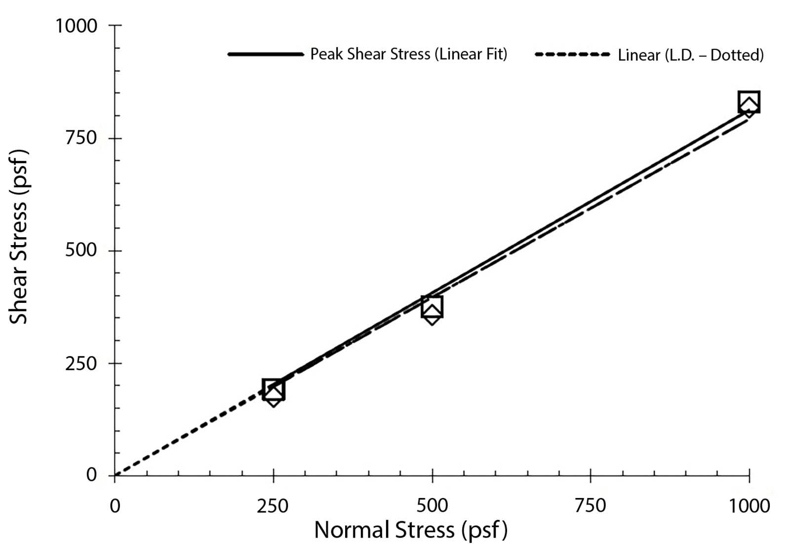
As shown in Figures 3a and 3b, the results indicate the factor of safety for veneer stability will be greater than the results calculated during the design phase. More specifically, the minimum interface friction angle determined necessary was 31° for static conditions and 31.9° for dynamic conditions (during construction). The laboratory results indicate the geocomposite/CCR peak and residual interface friction angles are 39.1° and 38.4°, respectively. Therefore, factors of safety using the laboratory interface friction angle are greater than those determined during the design, specifically:
- No seepage (critical slip surface considered to be the CCR/geocomposite interface), FS = 2.0
- Equipment forces due to equipment braking or stopping, FS = 1.7
The laboratory interface friction results further support the conclusion of the veneer stability analysis that stable slope conditions are anticipated where the soils are drained.
Construction
Crews could access the work area from an access road along the top of the perimeter berm with a small amount of space for construction staging. The steep slope of the berm (2.5H:1V) limited work to tracked-type equipment, such as bulldozers, excavators and a tracked front-end loader. Construction was performed over a short time frame to limit the duration of earth disturbance in the work area and higher potential for erosion. The normally driest summer months were targeted for construction to minimize difficulties associated with groundwater seepage and ending at the start of the fall growing season, with the objective of reestablishing vegetation on the slope as soon as possible.
Accordingly, construction began on July 7, 2014, and was completed by Aug. 20, 2014. Construction sequencing was used to reduce the risks of erosion and sediment transport.
Accessibility
The steep slope and access point presented challenges for construction of the geocomposite groundwater drainage system. Namely, the steep slope made construction of an access road cost-prohibitive due to the extent of earthwork needed to construct a road (not to mention increased concerns for stability if a road embankment were constructed on the 2.5H:1V slope). Therefore, equipment and materials were brought in from the top of the berm. The upper extent of the work area (upper limits of geocomposite) was approximately 100 feet (30 m) downslope from the top of the berm. The geocomposite extended down the slope another 100 feet (30 m) to the collection pipe, and erosion rills were repaired on the lower 130 feet (40 m) of slope, below the geocomposite area, down to the rubble mound revetment abutting Lake Michigan. The length and steep slope, along with a single access point, were safety concerns and required the use of tracked equipment that was stable enough to safely traverse the slope.

Sequencing
The manhole and downslope conveyance pipe were installed first. Then the work area was divided into five subareas to be completed, including seeding and placement of an erosion mat, before starting the next subarea to minimize the amount of exposed soil during construction. The general construction sequence for each subarea was:
- Strip vegetation and fine-grained soils in geocomposite area
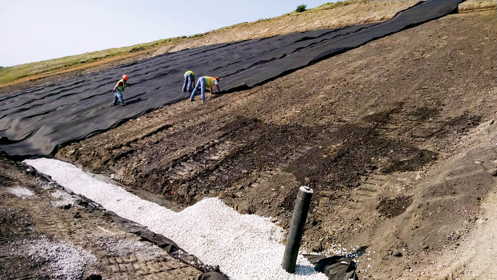
- Install approximately 100 feet (30 m) of collection pipe (drainage stone wrapped in nonwoven geotextile) (Figure 4)
- Excavate anchor trench and install geocomposite drainage layer
- Place fine-grained soils over drainage geocomposite
- Place topsoil over fine-grained soils
- Fill and compact rills in downslope area
- Seed and install erosion mat
The stripped vegetation contained some soils and was pushed upslope of the work area for use as a stormwater diversion berm. The fine-grained soil was then stripped and stockpiled downslope of the geocomposite area.
The geocomposite drainage layer was installed after excavation of the anchor trench and installation of the perforated collection pipe (Figure 5). The geocomposite was installed using continuous panels from the anchor trench to the collection pipe. This was done to avoid end seams on the slope, which can create a potential weak zone in the geocomposite. This is particularly a concern during placement of the overlying soils.
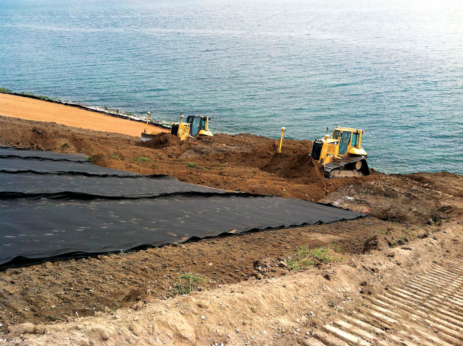
Placement of the fine-grained soil over the geocomposite was performed using a bulldozer, pushing the soil from the bottom of the geocomposite area up the slope (Figure 6).
Topsoil was not present on the berm slopes, and organic materials required to establish the vegetative layer were not available on-site. Therefore, topsoil was imported and stockpiled at the top of the east berm. A tracked front-end loader hauled the topsoil from the top of the slope to the work area and a 6-inch (15 cm) thick layer of topsoil was spread over the areas to be restored using a bulldozer.
Subsequent relocation of CCR
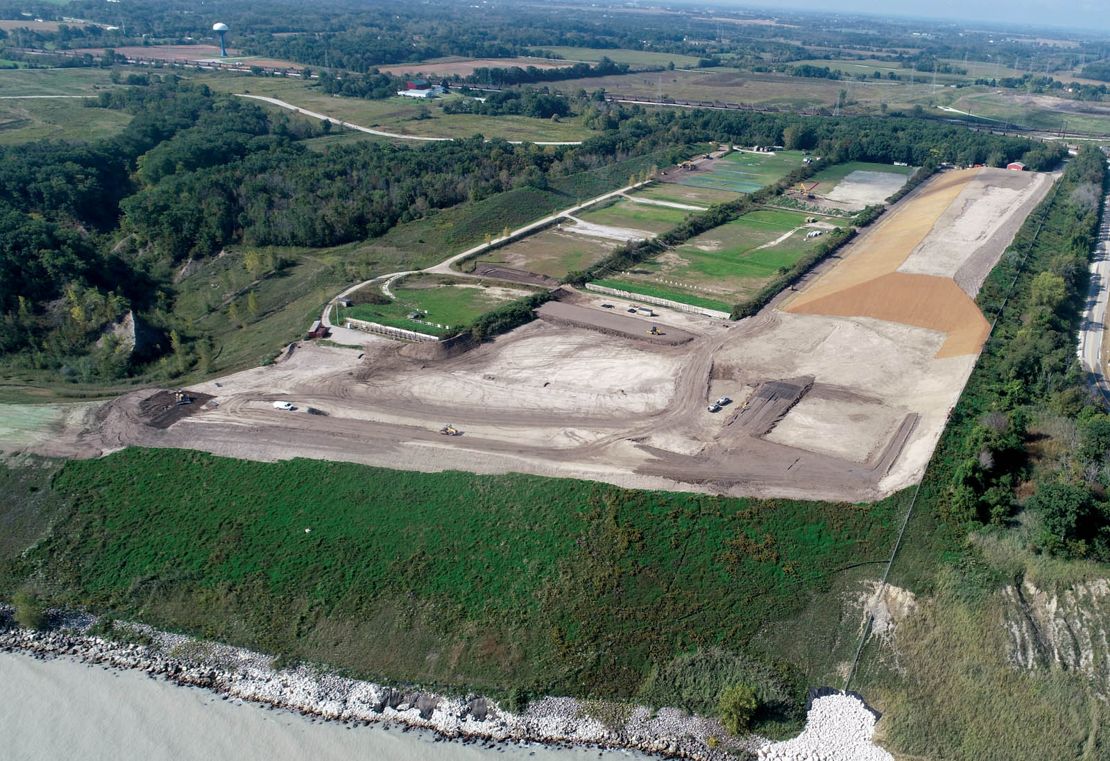
To further reduce the risk of continued erosion causing sloughing and CCR entering Lake Michigan, the berm along the lake was reconfigured during the summer of 2018 to relocate most of the CCR on the lake bluff. The height of the berm was reduced 33 feet (10 m), resulting in the relocation of approximately 320,000 cubic yards (245,000 m3) of CCR located above the geocomposite groundwater drainage system. The upper edge of the geocomposite was exposed and pulled back during earthwork, and laid back in place and buried following completion of CCR relocation. The resulting configuration of the berm has the geocomposite drainage system positioned along the top of the berm. A photograph of the reconfigured berm is provided in Figure 7 and indicates that no additional erosion of the outboard slope had occurred since installation of the geocomposite drainage system in 2014, as the outboard slope was not disturbed during reconfiguration of the berm.
Summary and conclusions
Erosion and raveling of surface soils covering a berm containing CCR was occurring on a steep slope on the shore of Lake Michigan due to groundwater seepage near the interface between the natural bluff soils and overlying CCR. The seepage was occurring above an existing groundwater collection trench; therefore, a geocomposite groundwater drainage system was designed and constructed to safely convey groundwater seepage to the lake to prevent additional erosion. The limits and scope of the geocomposite groundwater drainage system were determined during field reconnaissance. Established design guidance was used to determine the minimum performance requirements with respect to veneer stability and geocomposite transmissivity. Minimum design requirements were verified in the laboratory using site-specific materials. Despite the steep slope and other access limitations, construction was completed during the drier summer months in time for establishment of vegetation prior to the wet season. To further minimize the risk for erosion and exposure of the CCR in the berm, the berm was subsequently reconfigured to reduce its height and relocate most of the CCR.
Thoughtful planning, design and implementation produced a successful project anticipated to provide significantly reduced erosion potential and increased surficial slope stability.
References
Giroud, J. P., Zornberg, J. G., and Zhao, A. (2000). “Hydraulic design of geosynthetic and granular liquid collection layers.” Geosynthetics International, 7(4–6), 285–380.
GRI Report #30. (2005). “Direct shear database of geosynthetic-to-geosynthetic and geosynthetic-to-soil interfaces.” Geosynthetics Research Institute.
GRI Standard GC-8. (2001). “Determination of the allowable flow rate of a drainage geocomposite.” Geosynthetics Research Institute.
Narejo, D. (2004). “Long-term performance considerations for geonet drainage geocomposites.” Presented at the 57th Canadian Geotechnical Conference, Quebec, Que., Canada.
Schroeder, P. R., Lloyd, C. M., and Zappi, P. A. (1994). “The hydraulic evaluation of landfill performance (HELP) model: User’s guide for version 3.” EPA/600/R-94/168a. Sept., U.S. Environmental Protection Agency Office of Research and Development. Washington, D.C.
USACE. (2003). “Slope stability engineer manual.” EM 1110-2-1902. Department of the Army, U.S. Army Corps of Engineers. Washington, D.C.