 TEXTILES.ORG

By Jeffery T. Hoilman and Stanley M. Miller

Mountain Creek flows through the community of Red Bank near Chattanooga, Tenn., to the Tennessee River. Mountain Creek has been identified by the Tennessee Department of Environment and Conservation (TDEC 2018) as a 303(d)-listed stream, meaning that its pollution exceeds the state’s standards for one or more water quality criteria. Habitat alteration has been identified as the main source of pollutants and is due in part to channel erosion caused by urban development and increased stormwater runoff. A previous study (Schorr et al. 2001) conducted on the Mountain Creek watershed indicated that erosion of the stream channel is estimated to be between 66% and 81%. A project was proposed to reinforce approximately 105 linear feet (32 meters) of creek bank that was located along a meander bend, stabilize the slope leading from an elementary school’s access road to the creek, improve water quality in the watershed and protect the school’s outdoor nature classroom (Figure 1).
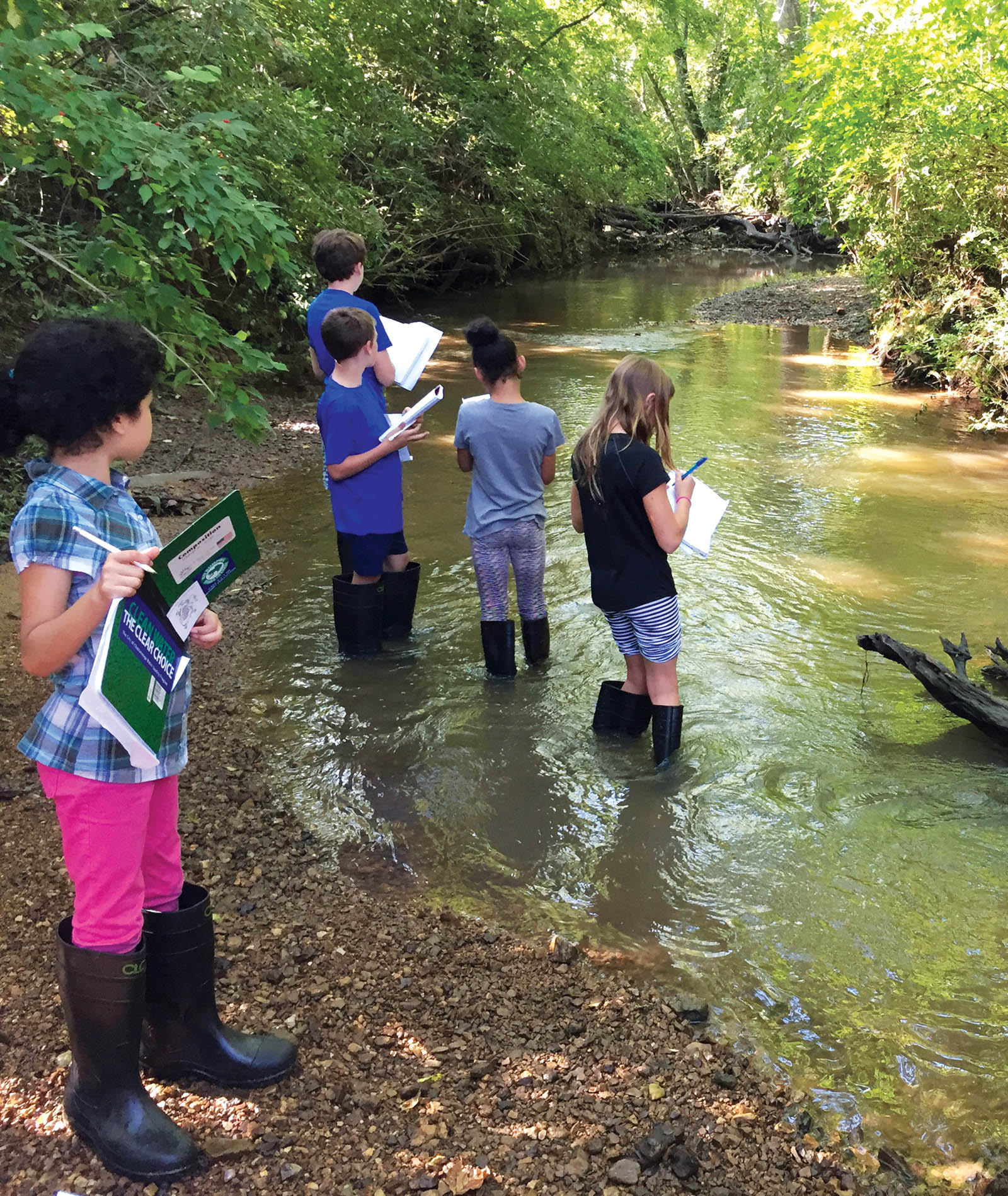
This restoration project was spearheaded by TenneSEA (Tennessee Student Environmental Alliance), a Chattanooga organization that collaborates with communities to teach children about their connection to nature. TenneSEA reached out to local Red Bank Elementary alumni who are involved in floodplain management, stormwater, and the erosion prevention and sediment control (EPSC) industry. A collaborative team of local businesses, nonprofit organizations, the school and government agencies donated their time and resources to tackle the project. Students at Red Bank Elementary also played a part by participating in the “Stream Team” (Figure 2). The program teaches students about the natural world around them by solving real-world problems while developing sustainable solutions. Students learned about the Mountain Creek watershed, flooding, EPSC and water quality. They were also involved in the engineering design and construction oversight. After evaluating several engineering and geotechnical options to restore the streambank, stabilize it to resist future erosion and provide a sustainable solution, engineers chose a combination of SCOURLOK Engineered Bank Stabilization (EBS) and ARMORMAX 75 Engineered Earth Armoring Solutions (EEAS).
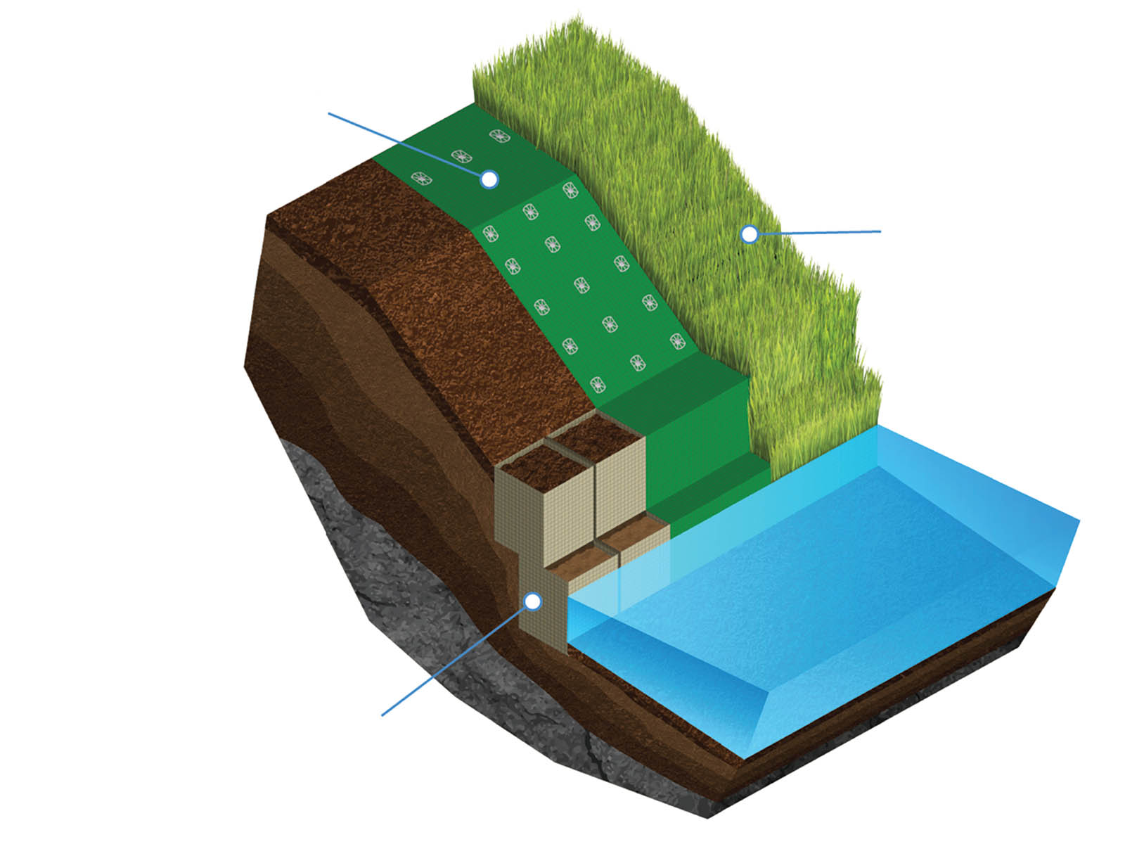
EBS is a new system/best management practice to resist extreme hydraulic stresses. EBS systems are designed to help protect streambanks, shorelines and other similar applications while promoting vegetation in lieu of hard armor. Additionally, it provides water quality benefits including pollutant and nutrient removal. The EEAS was used to stabilize the slope above the streambank to prevent erosion from larger runoff and flooding events. This system combines geotextiles and a high-performance turf reinforcement mat (HPTRM) with engineered earth anchors (EEA) to provide additional surficial slope stability (HPTRM + EEA). Figure 3 depicts the typical layout used on the Mountain Creek streambank restoration project.
Gravity retaining walls
In recent years, as site conditions allow, project designers have sought vegetated facing on these structures rather than traditional hardscape systems (i.e., rock riprap/rockery, concrete blocks or rock-filled wire-frame units). An EBS system acts as a vegetated gravity retaining wall. Gravity retaining walls rely on the weight of the wall system itself to counteract the lateral earth pressures due to the retained soil. The most common gravity walls currently in use are comprised either of rock-filled gabions or of large concrete blocks, each weighing 1,800 pounds (816 kg) or more that interlock together in a dry-stack fashion to construct retaining walls typically up to 12 feet (3.6 m) high. To reach such heights without additional artificial reinforcement, the face batter angle is increased to 12˚–16˚ and/or a wider (thicker) base block is used on the bottom course of blocks to increase resistance to base sliding and to overturning moments.
Components and capabilities
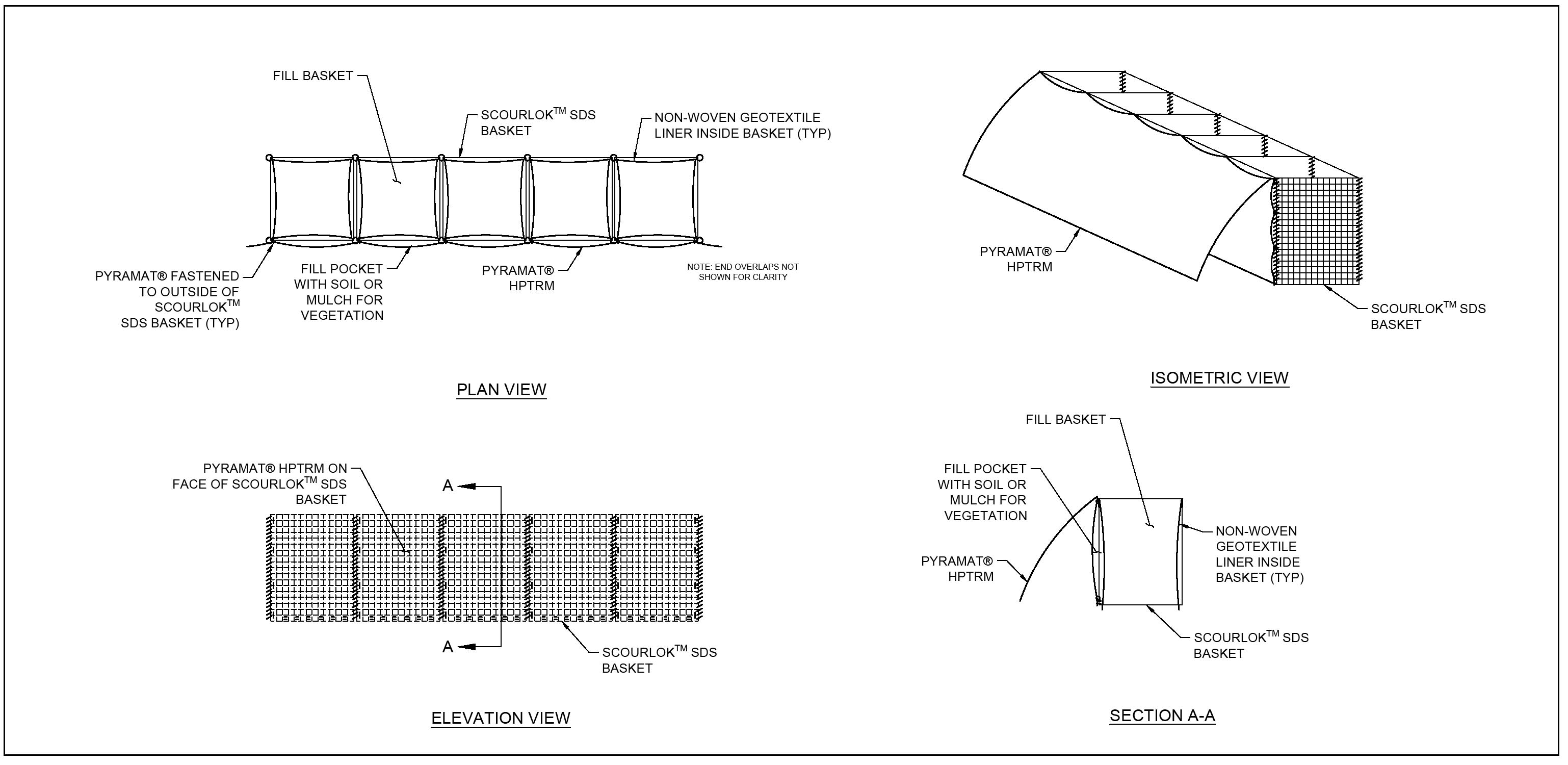
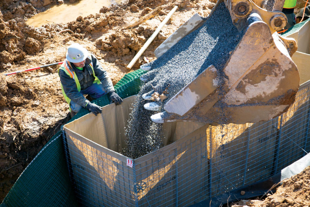
The EBS system essentially is comprised of a pyramidal-woven HPTRM and rigid galvanized (or stainless) welded metal cells that are internally lined with non-woven geotextile that form compartmentalized units 3 feet thick × 4 feet high × 15 feet long (0.9 × 1.2 × 4.6 m). Each unit is then comprised of five cell compartments that are 3 × 3 × 4 feet (0.9 × 0.9 × 1.2 m) and are open at the bottom and top, which allows ready setup and filling at the project site (Figure 4). When several of these units are linked together in a series, they form a gravity wall system that is 4 feet (1.2 m) high and 3 feet (0.9 m) thick.
The EBS system can be shipped folded and flat, then expanded out like an accordion, transforming into the segmented units that can be stood up on a level, prepared surface and then filled from the open top with soil or gravel.
The HPTRM wrap is fastened to each rigid cell to provide a flexible exterior that controls erosion while providing sufficient tensile strength and UV resistance for excellent long-term performance. Additionally, it forms pockets that can be filled with mulch or other media to promote and sustain vegetation. The durable geotextile lining allows the rigid cells to be filled with soil, sand, gravel, crushed rock and other granular material. The units (bastions) can be stacked on top of each other, using a setback distance of 0.5–1.5 feet (15–46 cm), thus forming walls up to 12 feet (3.6 m) high (Figure 5).
The EBS system walls must be founded directly on native soil or approved structural fill. In most cases, subgrade preparation involves using an excavator with a smooth-blade bucket to remove topsoil and organic detritus to reach native, undisturbed soil and provide a smooth shallow trench to place the initial row. If the foundation soil comprises clay or elastic silt, which are moisture-sensitive soils, or the design requires a more frictional base, then a compacted gravel leveling pad should be placed. Additionally, a drainage pipe system to remove excess groundwater at the base of the wall should be installed in conjunction with the foundation. If a foundation drain pipe is used, then it must have a proper outlet for water disposal or conveyance to low points. For sites prone to water submergence, the first row of bastions can be filled with coarse gravel to allow free movement of water without pore-pressure buildup (Figure 6).
It is recommended that soil infill for the EBS system meet the following specifications:
- Classified as GM, GW-GM, SM, SW-SM, SC-SM, CL-ML or ML using the Unified Soil Classification System (USCS)
- Contains maximum particle size of 3 inches (7.6 cm)
- Has a plasticity index (PI) of fines not exceeding 10 and a liquid limit not exceeding 30
- Has natural or conditioned moisture content to allow proper compaction
- Contains no deleterious substances (wood, metal, plastic, waste, etc.), hazardous chemicals or pesticide/herbicide residue
Because the EBS system is flexible, curves can be incorporated along the wall or slope alignment. This is achieved for each successive lift by flexing and staking the units prior to backfilling.
Soil compaction control during construction is critical to the long-term performance of these gravity structures. Cell infill should be compacted with a moderate effort, allowing some packing of the soil without causing excessive swelling of the cell walls. Compaction is required in the backfill zone behind the cell wall. For small compaction equipment, such as vibratory plate compactors, the thickness of soil compaction lifts often is limited at 6–8 inches (15.2–20.3 cm) in order to achieve the specified density (per ASTM D1557). Effective compaction monitoring and verification help reduce the potential for differential settlement, which may adversely affect long-term performance.
Geotechnical design concepts
The weight of the bastion units must resist the lateral earth pressure due to the retained soil tending to deform and slide downward and outward due to the pull of gravity. Additionally, it must resist any lateral contribution from surcharge loading in the backslope area (such as permanent loads due to a building or bridge foundation or temporary loads due to traffic or construction equipment). The lateral earth-pressure force, Fa (measured in force per unit length of wall face; i.e., pounds/foot or kN/m) is estimated using the Coulomb active earth pressure coefficient Ka given by:

where: β = batter angle of wall (inclination of wall face from vertical)
ϕw = friction angle at wall-soil interface (typically 0.67 of the soil friction angle)
ϕ = friction angle of retained soil
θ = backslope angle
The lateral earth-pressure force (Figure 7) is:
Fa = 0.5γH2Ka (2)
where: γ = unit weight (density)
of retained soil
H = height of wall system
Lateral force due to any surcharge loading applied in the backslope area is:
Fq = qHKa (3)
where: H = height of wall system
q = surcharge loading, expressed as a pressure in units of pounds per square foot (psf) or kiloNewtons per square meter (kN/m2)
These forces tend to overturn (rotate by tipping) the gravity-wall system or cause it to slide horizontally outward along its base; thus, they must be sufficiently resisted by the weight of the wall units to provide long-term stability. In addition, a bearing capacity analysis (foundation) and a global stability analysis (overall stability of wall and back slope area using a method-of-slices approach) should be conducted to evaluate these potential modes of failure external to the wall system itself (Miller 2017). Optional ground anchors can be installed to form a “tieback” system if local site conditions warrant.
Oftentimes, a coarse granular (crushed gravel) backfill zone is included directly behind the EBS units to allow free drainage of groundwater and to increase the friction angle along the potential failure path through the retained soil. Using a weighted value of the friction angle along this path (a path intersecting some gravel and some retained soil) results in a lower computed value of Ka and, thus, increased stability of the wall system.

Geotechnical design criteria (i.e., factor of safety against failure) for the analyzed potential failure modes typically are prescribed as depicted in Table 1.
Mountain Creek layout
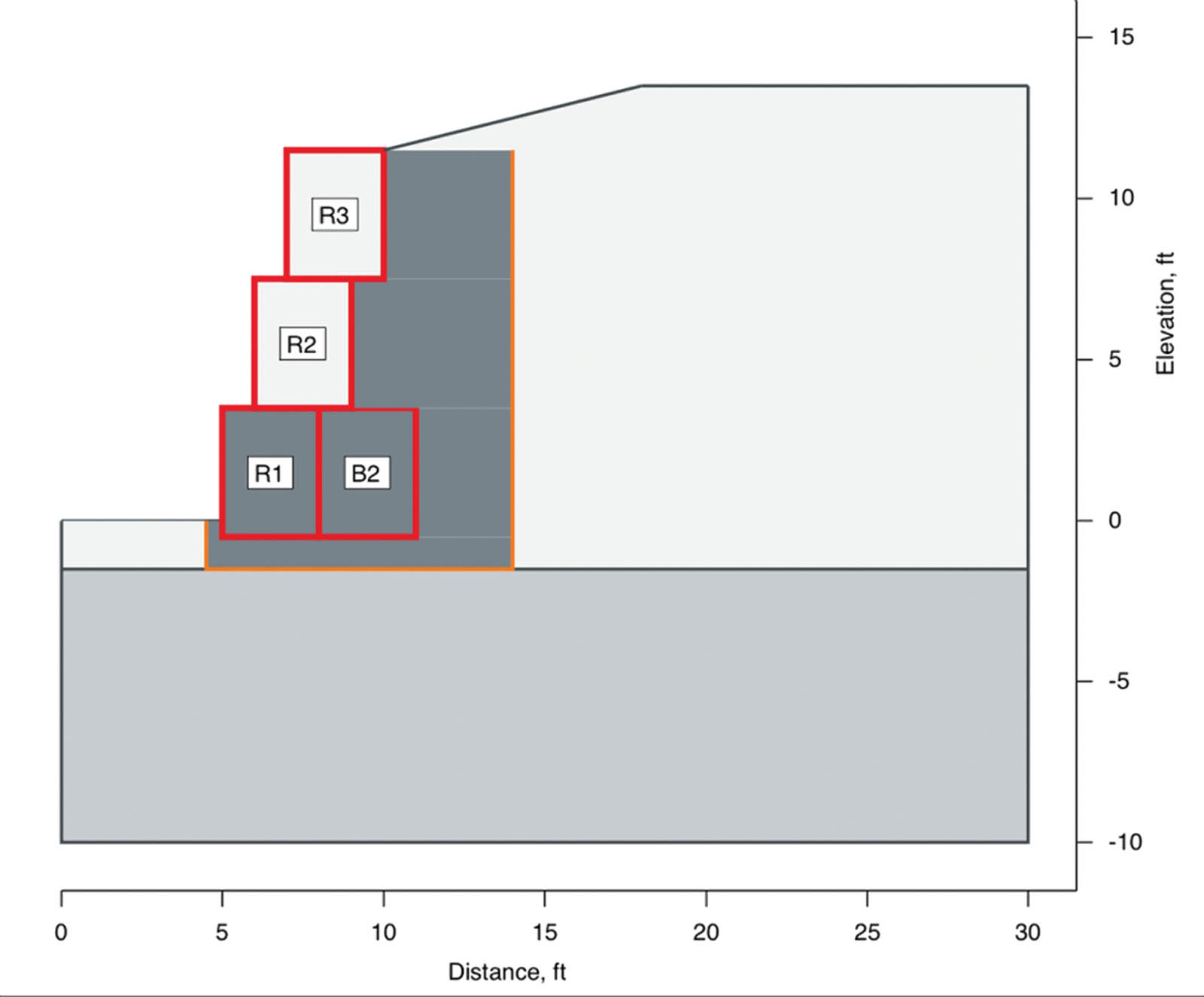
Due to the streambank height, floodplain and scour, a two-tiered EBS system with EEAs was used for the project and were set back 18 inches (46 cm). HPTRM + EEAs were used to stabilize and provide erosion protection to the 3H:1V slope above.
The foundation for the EBS units was placed approximately 18–24 inches (46–61 cm) below the streambed elevation for scour protection. A nonwoven geotextile and base stone were used to provide a stable foundation. EEAs were driven into the back slope for pullout resistance due to the soils and stream scour forces, with the channel being located within the meander bend.
The bottom row of the EBS units were filled and backfilled with stone material to allow water to move through the system during changes in water level elevations while allowing any pore pressure behind the system to be relieved.
The top row of the EBS units were filled, backfilled and compacted with existing clay soils located on the project site. An organic growth media was placed in the top 4–6 inches (10–15 cm) of the top units to allow for vegetation establishment.
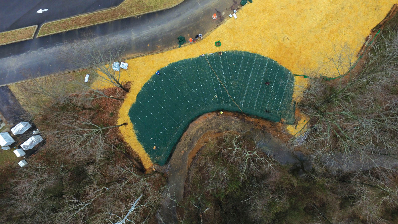
One hundred and five feet (32 m) of streambank was restored using the EBS system while the HPTRM + EEAs were used to stabilize and prevent erosion to the reconstructed 3H:1V backslope (Figure 8).
In order to establish permanent vegetation, the following materials were used on the project site:
Profile Products ProGanics and a starter fertilizer were placed on the reconstructed slope prior to the HPTRM + EEAs installation.
Profile Products Flexterra hydromulch with permanent seed was sprayed on top of the HPTRM.
The EBS vegetated pockets and tops were filled with a mixture of hardwood mulch, topsoil, Profile Products ProGanics (pellets) and permanent seed mixture.
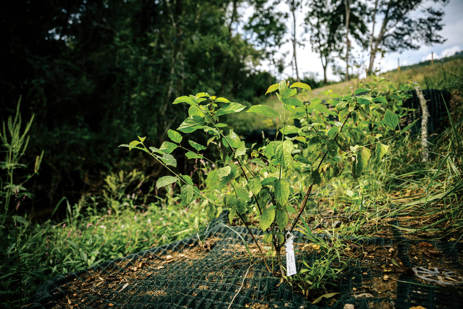
Native trees, shrubs and other plants were planted in the tops of the EBS units and various locations along the slope to reestablish a vegetated riparian buffer (Figure 9).
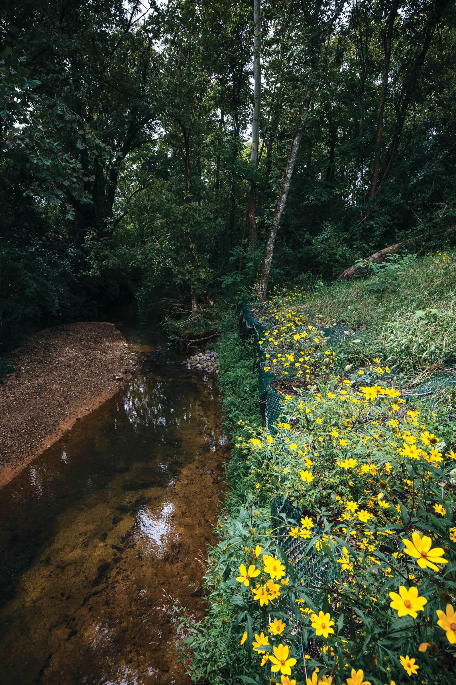
Figure 10 depicts the Mountain Creek project vegetation establishment in September 2018 nine months following construction.
Conclusion
The Mountain Creek streambank restoration project began in early December 2017 and was completed in January 2018. One hundred and five feet (32 m) of streambank and the above slope were successfully restored and stabilized. This restoration protected Red Bank Elementary School’s access road, prevented additional sediment from being deposited in an impaired watershed and most importantly provided a safe outdoor nature classroom where students can continue to take part in restoration efforts of the Mountain Creek watershed.
By combining rigid metal cells internally lined with a nonwoven geotextile and an outside HPTRM wrap, an easily constructible gravity-wall system is now available for streambank, shoreline and slope stabilization. The HPTRM wrap provides a flexible exterior, controls erosion and improves system durability while forming pockets that can be filled with mulch or other media to promote and sustain vegetation. The durable geotextile lining allows the rigid cells to be filled with earth, sand, gravel, crushed rock and other granular material. Potential projects range from landscaping enhancements for residential and commercial properties to large-scale shoreline protection, as well as landslide repairs requiring a toe buttress.
For remote project areas (or heavily wooded or steep sites) with difficult equipment access, the ability to easily transport or carry geosynthetic materials to the site is an advantage over heavier concrete blocks or large riprap. Remote sites along lakeshores, rivers, estuaries or coastlines could be accessed by boat, readily transporting materials and workers to the projects. Once the leveling pad or foundation is prepared, EBS units can be deployed and set up, ready for soil infilling.
Note that site investigation and characterization of geotechnical soil properties always are required to provide reasonable confidence in the wall/slope design. Construction oversight and monitoring is strongly recommended to confirm the site conditions concur with those assumed in the design analysis and to verify that construction practices follow the engineering design and specifications.
References
Chattanooga-Hamilton County Regional Planning Agency. (2002). Mountain Creek community greenway master plan, p. 24. https://chcrpa.org/wp-content/uploads/sites/17/2017/12/MtnCreekGreenwayfinal_plan_document.pdf.
Miller, S. M. (2017). “Versatile applications of internally braced, geosynthetic wrap-face vegetated walls and reinforced soil slopes.” Geosynthetics, 35(4), 24–33.
NCMA (National Concrete Masonry Association). (1996). Design manual for segmental retaining walls, 2nd ed., Herndon, Va.
TDEC (Tennessee Department of Environment and Conservation Division of Water Resources). (2018). www.tn.gov/environment/program-areas/wr-water-resources/water-quality/water-quality-reports—publications.html.
Jeffery T. Hoilman, P.E., CPESC, CPSWQ, CESSWI, is market development manager for Propex Operating Company LLC.
Stanley M. Miller, Ph.D., P.E., is professor emeritus in the Department of Civil Engineering at the University of Idaho and an engineering consultant.
All photographs, illustrations and tables courtesy of the authors.