 TEXTILES.ORG

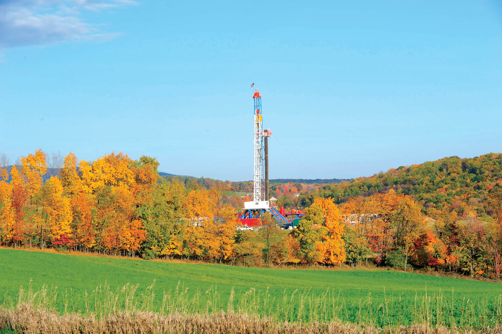
While natural gas contained within shale rock is geologic and thus ancient by its very nature, the practice of its removal by horizontal drilling coupled with hydrofracking is a relatively recent development (Figure 1). Indeed, these dual technologies are making possible the recovery of huge amounts of natural gas—so much so that one can envision natural gas as an energy source rivaling oil, coal and nuclear. The potential in this regard is awesome, particularly since it is worldwide in its availability and opportunities.
This paper describes shale gas drilling and extraction operations, along with associated environmental concerns. Using this as a background, the paper then describes and illustrates many geosynthetic materials opportunities that exist, making the overall operations more efficient, economical and environmentally acceptable.
Shale gas plays
Shale is a fine-grained sedimentary rock that is formed by heat and pressure over geologic time. Many formations contain organic materials (shale gas plays [formations] are then called “oil shales”), which upon decay, generate natural gas within the rock itself. The liberation, capture, transmission and utilization of this gas is at the heart of the technology. It should be mentioned that natural gas has traditionally accompanied oil-drilling operations and has historically been seen as a nuisance to oil drillers. However, this same gas now takes center stage insofar as its energy production is concerned.
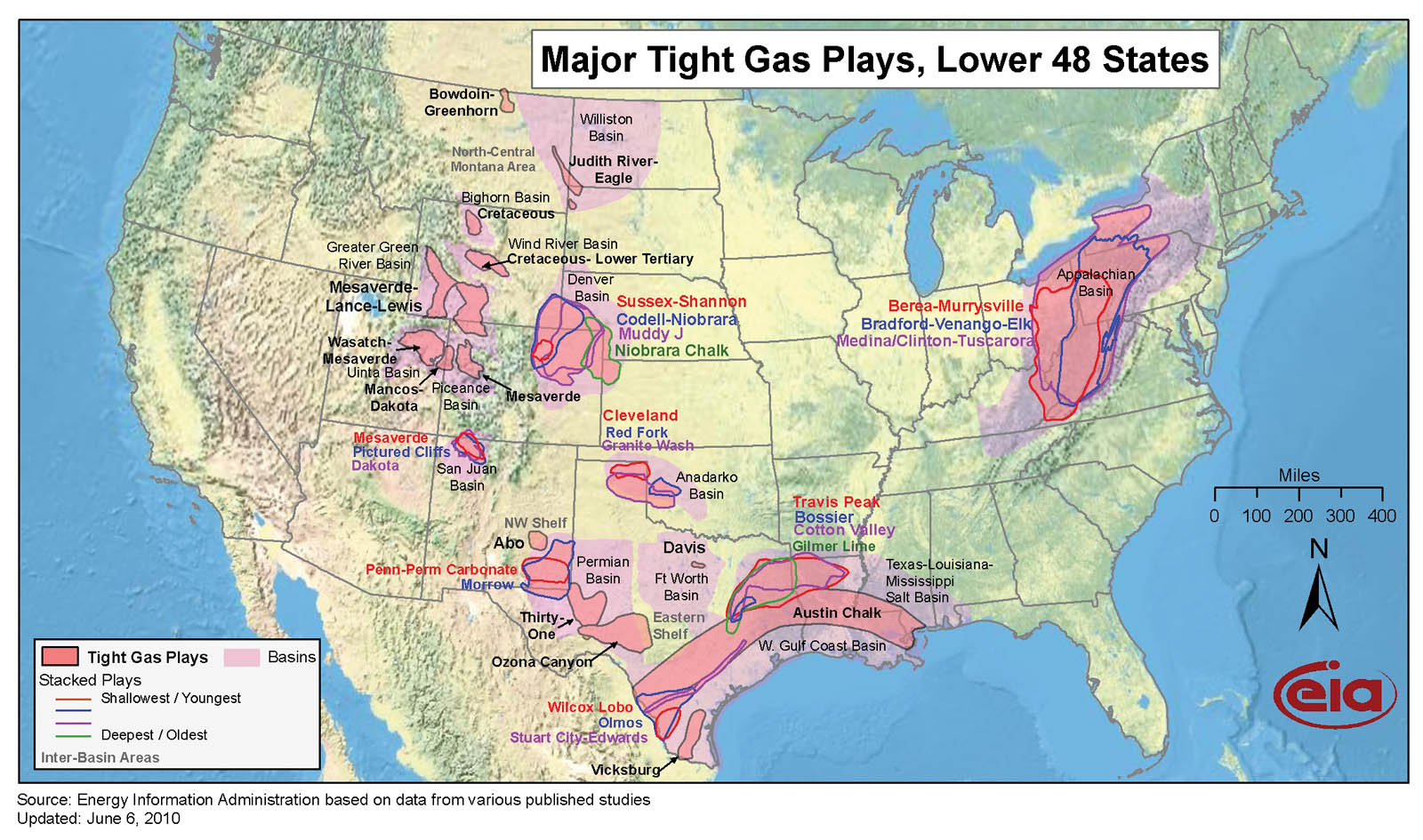
Shale gas plays are found worldwide. In the United States, there is activity in many states, as Figure 2 indicates. Of the locations shown, the Barnett Formation in the Fort Worth Basin in Texas is very significant since it was the first large-scale operation using these newer drilling and extraction technologies. By 2004 it had been explored by 15,000 deep wells and had produced 1.4 trillion cubic feet (0.04 trillion cubic meters) of natural gas. Horizontal drilling at great depths coupled with hydrofracking was perfected in the Barnett Formation.
A more recent major gas play is in the Marcellus Formation underlying major parts of Pennsylvania, New York, Ohio and West Virginia. Figure 3 on page 24 shows the extent and depth of this formation, in which it is seen to be near surface in Ohio, but 7,000 feet (2,100 m) underground in Pennsylvania and New York. The Marcellus Formation is 800 feet (244 m) thick in these two states and only 50 feet (15 m) thick in Ohio. Pennsylvania is in full production of natural gas with 2,208 producing wells in 2017 (up from 115 in 2004). For more information on the state’s natural gas production, see Pennsylvania State University’s Marcellus Center for Outreach and Research (www.marcellus.psu.edu).

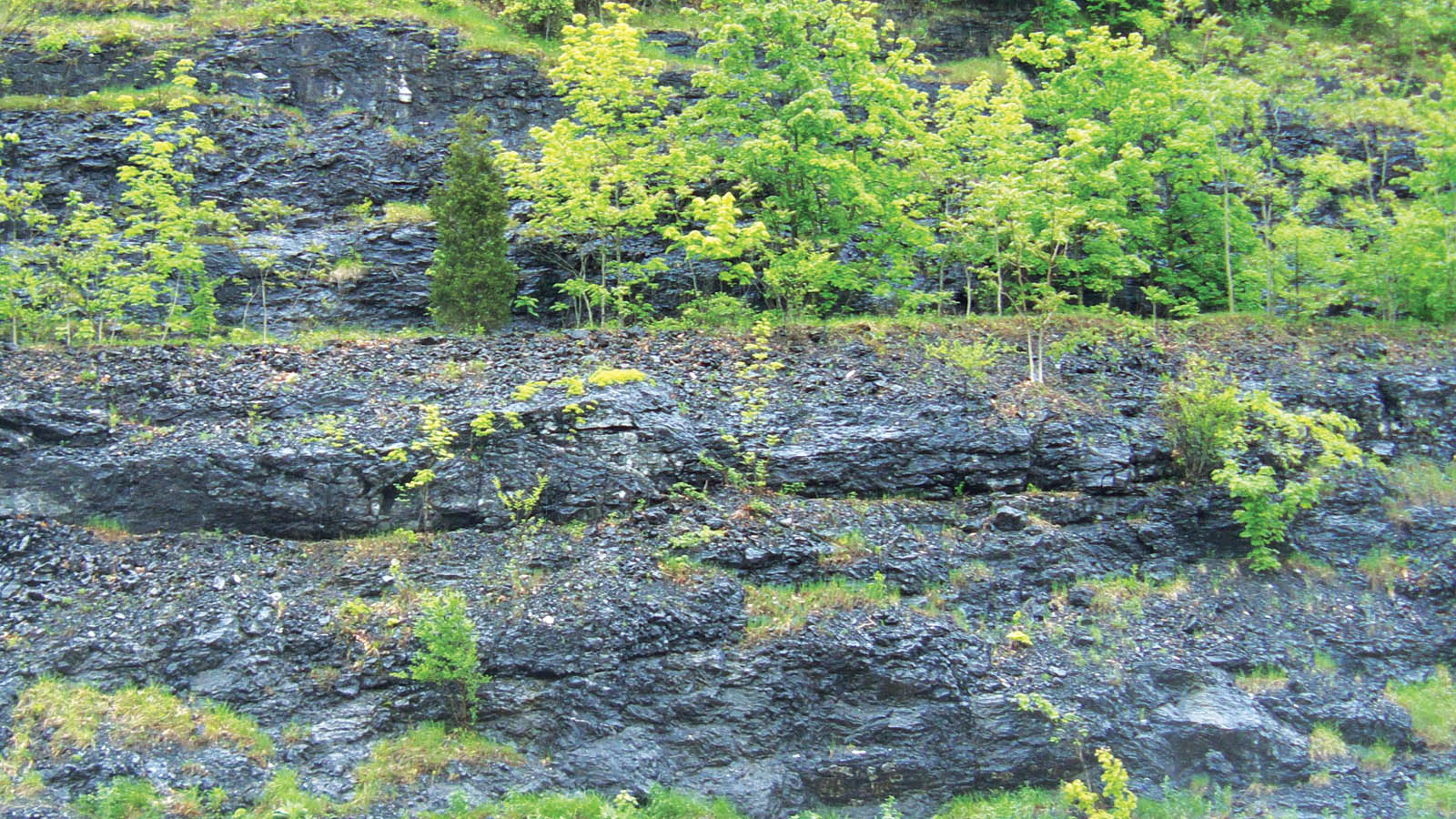
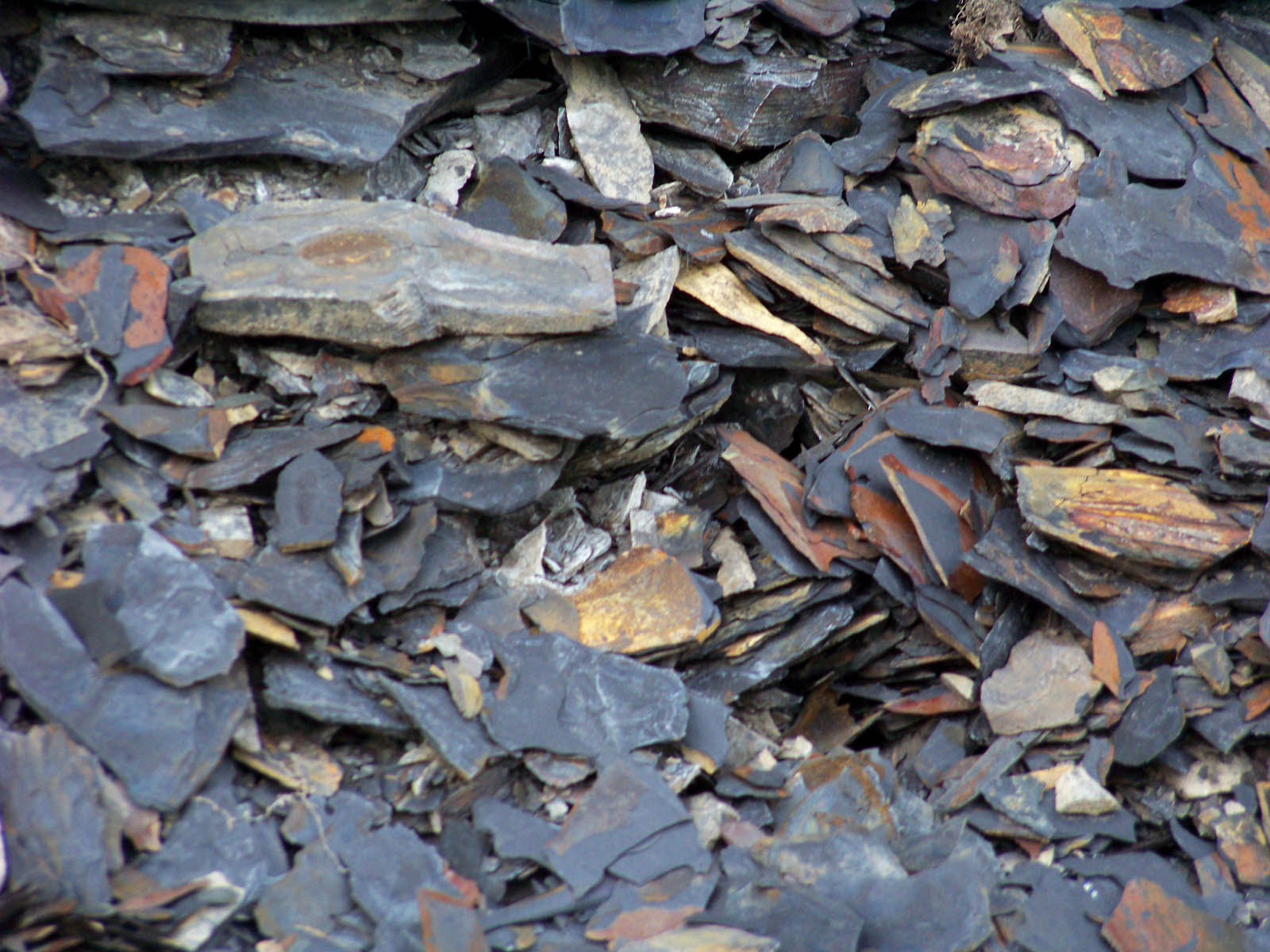
The Marcellus Formation is a 400-million-year-old marine sedimentary rock named for an outcrop near Marcellus, N.Y. The bedding is well developed, and it is relatively easy to fracture. That said, at these depths it requires approximately 15,000 pounds/square inch (103 MPa) of pressure to accomplish the fracking. The in situ and surface-exposed features are shown in Figures 4a and 4b. Its organic content varies from 1% to 10%, and it sometimes contains enough carbon to support combustion.
The U.S. Department of Energy (DOE) estimates that the Marcellus contains 262 trillion cubic feet (7.4 trillion m3) of natural gas. Conversely, the estimates of Professor Terry Engelder of Pennsylvania State University are much higher, i.e., 4,360 trillion cubic feet (123 trillion m3), a total of which 1,310 trillion cubic feet (37 trillion m3) are recoverable. At a market price of $0.02/cubic foot ($0.71/m3), the DOE estimated value of the recoverable gas is $5.2 trillion, while Engelder’s estimate is $26.2 trillion. Whatever estimate holds true, the financial incentives are enormous. Additionally, Professor Timothy Considine of the University of Wyoming estimates that a typical Marcellus well generates $2.8 million in direct economic benefits; another $1.5 million from workers and landowners; and $2.0 million in federal, state and local taxes. This type of financial incentive is, of course, reflected in the present activity associated with shale gas extraction, transportation and eventual use as an energy source.
Regulations and environmental concerns
The Energy Policy Act of 2005 was, and is, the foremost federal regulatory act governing shale gas plays of the type described in this article. Two aspects of this legislation have attracted considerable controversy:
- Hydrofracking was exempted from the Safe Drinking Water Act (1974).
- Chemical additives to the water used for fracking were exempted from disclosure.
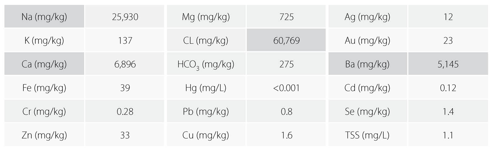
To gain some perspective in this latter regard, a chemical analysis of the flowback frackwater (at a specific site) is of interest (see Table 1). Note should be made of the highlighted alkaline minerals, which result in a brackish liquid about five times the salinity of seawater. Also to be mentioned is the number of heavy metals, although the quantities are thought to be relatively low.
It should be noted that federal legislation, the Fracturing Responsibility and Awareness of Chemicals (FRAC) Act of 2009, requires disclosure of fracking chemicals and places the entire process under U.S. Environmental Protection Agency (EPA) regulations.
At the state level in Pennsylvania, shale gas operations are regulated under various departments, for example:
- Drilling via the state’s Oil & Gas Division
- Fracking water via the state’s Field & Stream Division
- Well cuttings and waste disposal via the state’s Solid Waste Division
In keeping with an emotionally charged technology, such as extracting natural gas, there are many environmental issues that have been raised by various concerned organizations, such as federal, state and local regulatory groups; local water authorities; various industry groups; and concerned citizens groups. Some issues raised (but clearly not all) are mentioned below. This list of issues has been selected because of the potential of using geosynthetic materials to solve, or at least mitigate, the concerns:
- Containment and storage of large quantities of surface water for drilling and fracking purposes
- Storage and reuse of flowback water from the hydrofracking process
- Proper disposal of the “cuttings” from drilling operations (approximately 1,000 tons [907 tonnes] per well)
- Drill pad site contamination (each site being typically 3–5 acres [1.2–2.0 ha] in size)
- Frack tank and storage area contamination
- Access roads, parking and staging areas, and maintenance thereof
- Minimizing site disturbance, and providing level staging and working areas
- Soil erosion and temporary containment to avoid stream and property contamination
In this regard, some knowledge of drilling operations is important insofar as site development and maintenance. For example, a typical well site contains three to six vertical wells, each of which has horizontal branches going in different directions. Also, each well is hydrofracked several times. This iterative process depends upon the diminishing gas yield over time. Lastly, it is anticipated that a well pad should have a usable lifetime of approximately 20 to 30 years.
Furthermore, the following generalized goals with shale gas extraction are interesting to keep in mind as we now go into geosynthetic opportunities and solutions:
- The drilling operations are large construction projects with considerable public and regulatory scrutiny.
- Once permitted, fast mobilization and deployment are necessary.
- A low profile is advantageous throughout, particularly through the minimization of truck traffic.
- Benefit/cost is always important, but maximizing benefit often outweighs minimizing cost.
Geosynthetic opportunities and solutions
This section of the article describes some of the many geosynthetic opportunities and solutions that can be applied to shale gas plays. The section is subdivided into (1) the drilling operations themselves, (2) opportunities and solutions at permanent locations, and (3) opportunities and solutions at temporary locations.
Geosynthetics associated with drilling operations
The first, and quite obvious, opportunity is the use of geomembranes for fresh-water containment and subsequent use in drilling operations. The geomembrane design stages are well known and consist of the following sequential steps:
- Geometry (length, width, depth)
- Cross section materials
- Geomembrane type
- Geomembrane thickness
- Subgrade soil stability
- Cover soil stability
- Runout and anchor trench details
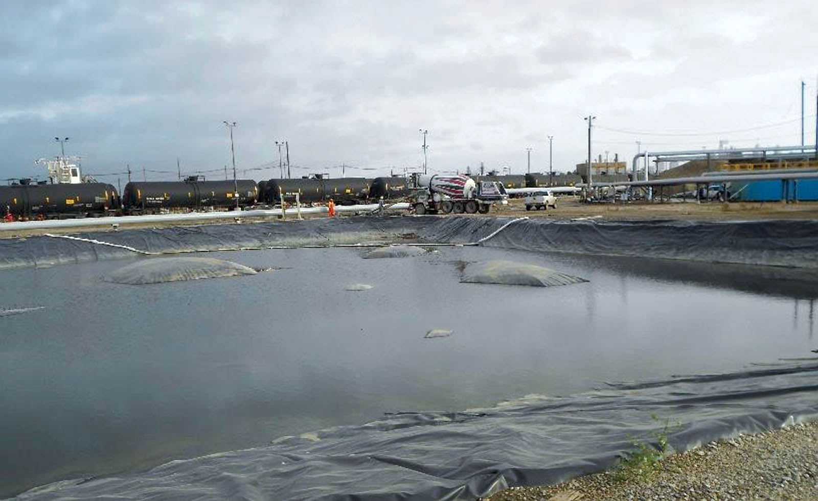
Perhaps the most overlooked design detail is the requirement of providing an underdrain system beneath the geomembrane. Shown in Figure 5 are the all-too-common “whales” lifting up the geomembrane via rising gases within the underlying soil subgrade. Various underdrain solutions that should be considered in the design state include using one of the following:
- Thick needlepunched nonwoven geotextiles
- Drainage geocomposites (complete or strips)
- Interconnected perforated pipe system
- Geotextiles with small perforated pipes
- Sand bedding layer (with pipe network)
The second opportunity is the containment and reuse of the flowback water, which was characterized in Table 1 on page 25 and is seen to be quite contaminated. Presently, this water is largely being held in mobile holding tanks, which, to the authors, seems to be a questionable solution. Alternatively, single or double geomembrane-lined ponds or even underground storage systems offer attractive alternatives.
The third opportunity for geo-membranes and related geosynthetics is the containment of cuttings from the drilling operation itself insofar as proper safe and secure disposal is concerned. In this regard, it should be mentioned that each well produces about 1,000 tons (907 tonnes or ~75 truckloads) of contaminated cuttings.
These cuttings can, of course, go to a licensed public or private landfill but alternatively can be placed in geo-
textile tubes at the site, and can even have a decontaminant added such that the treated effluent can be released to the environment. The addition of charcoal, activated carbon, phosphoric rock or organoclays are alternatives and all are within the decontamination technology that is associated with geotextile tubes.
Opportunities and solutions at permanent locations
Roadways into and out of drilling sites (often on private land) are the first priority in this category. Keep in mind they are necessary for the 20- to 30-year lifetime of the operations. Geotextiles and geogrids have been shown to save from 10% to 50% of the crushed-stone thickness of base courses placed on soil subgrades. The functions of separation, stabilization and/or reinforcement are clearly indicated in the literature since this application has been ongoing for 35 years.
A second way of reducing crushed-stone thickness is offered by using geocells. They are filled with gravel, sand or locally available soil and their design (which uses a geotextile beneath them) is well established. Thicknesses saved are at least 50% thinner than gravel by itself.
Third, these same geocells in a thinner format are ideal for parking and staging areas located adjacent to the drill pad.
Fourth, locally available soils (even silts and clays) can be meaningfully strengthened by the addition of discrete fibers or microgrids. Both types lead to major increases in shear strength in the upper 4 to 12 inches (10–30 cm) of the ground surface. The technology is currently well advanced and mature.
Fifth, the drill pad site along with adjacent parking and staging areas must be level. To accomplish this in hilly terrain (as is typical in the Marcellus Formation area), the design engineer needs to create reinforced soil slopes or vertical walls. The concepts of mechanically stabilized earth (MSE) slopes and walls using geogrid or geotextile reinforcement are ideal. Not only are these situations the least expensive of all types of retaining structures, they are straightforward to construct; have no limitations as to curvature, height or orientation; and have proven stable insofar as extreme surcharge loads are concerned.
Sixth, the drill pad itself should be lined to avoid ground contamination from spilled frackwater, hydrocarbons or other potential contaminants. This calls for a geomembrane, a geosynthetic clay liner or both as a geocomposite liner. There are many choices in this regard and a designer should consider generating a benefit/cost ratio to select the appropriate liner material. In it, the procedural steps are as follows (see www.geosynthetic-institute.org/papers/paper12.pdf for a numeric example):
- Select relevant site-specific properties as per application.
- Weight properties from 10 (high) to 1 (low).
- Select candidate geomembrane types.
- Grade types from 5 (high) to 1 (low).
- Multiply weight by grade.
- Add resulting numbers.
- Divide by estimated unit costs.
- Select the geomembrane type with highest benefit/cost ratio.
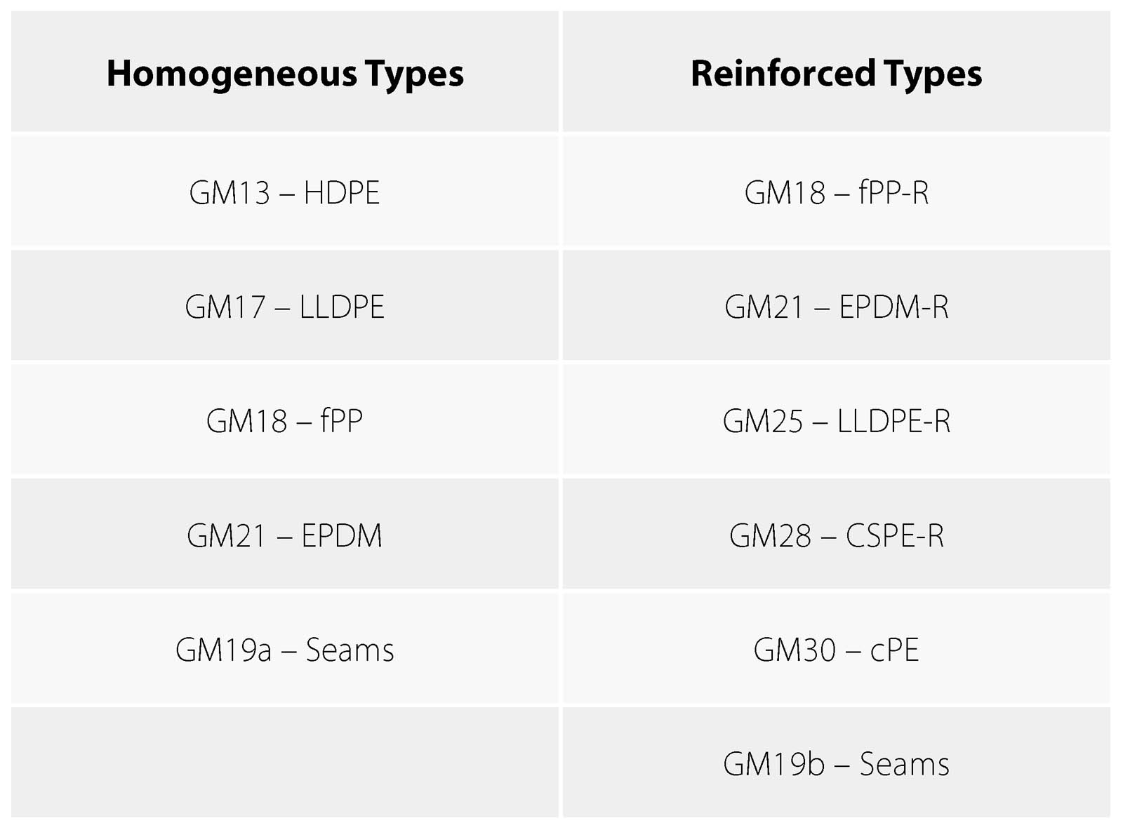
Upon geomembrane selection, the engineer must now specify the properties. Beginning in 1990, the Geosynthetic Institute (GSI), via its member organizations, has been developing generic specifications available for common liner materials. Those currently available from GSI are in Table 2 (see www.geosynthetic-institute.org/specs.htm for details). For PVC geomembranes, see ASTM D7176.
Seventh, natural gas plays are replete with plastic pipe. Such pipe is used for many purposes, such as:
- Freshwater transmission
- Frackwater transmission
- Gas transmission
- Surface water drainage
- Underground well pad drainage
The pipe is generally high-density polyethylene (HDPE) or polyvinyl chloride (PVC), and can be solid wall (for transmission) or corrugated with slots or holes (for drainage). Whatever the case, natural gas plays require the use of a considerable amount of plastic pipe.
Opportunities and solutions at temporary locations
Temporary roadways lasting weeks or months are necessary in connection with setup and eventual demobilization at natural gas play sites. The geosynthetics industry has the capability of providing wearing surfaces placed directly on the ground surface and removed after use. Light and heavy roadway systems developed by the Dutch military for rapid deployment of heavy vehicles and equipment have used this technique. The geosynthetics are typically 60 feet (18 m) long and 10 feet (3 m) wide, and the weight varies with type. They can be redeployed as often as necessary.
Temporary dams may be used for surface water control or for accidental spills associated with the drilling or containment operations. Geomembranes can readily provide such temporary containment and be adaptable to myriad situations.
On sloping surfaces, soil erosion is a concern and must be avoided to prevent silting of off-site areas and local streams and rivers. Geotextile silt fences have played an economical role in this regard for decades.
Rather than containing the site’s erosion after it occurs, it is better to control and stabilize it before it starts. This has been traditionally provided by geosynthetic erosion control materials. The two major design categories are for slopes and channels/ditches. A myriad of products are well advanced in both cases.
Conclusion
Natural gas plays (including drilling, the well pad, staging and parking areas, permanent and temporary roadways, and access areas) are major construction projects resulting in enormous natural gas energy production. They also have attracted considerable public and regulatory scrutiny. That said, once permits are obtained (which is not an easy task), fast mobilization, deployment and operations are necessary. Within the entire activity, a low-profile exposure is always an advantage. All these aspects can capitalize on geosynthetics in a major way.
Of course, and within acceptable environmental criteria, benefit/cost analyses are always required for alternative and competing systems. We feel that in so doing, geosynthetic materials will invariably be the obvious solution for many of these applications.
Acknowledgments
The financial assistance of the member organizations of GSI and its related institutes for research, information, education, accreditation and certification is sincerely appreciated. Their identification and contact member information are available on the institute’s website, www.geosynthetic-institute.org.
Robert M. Koerner is professor emeritus of civil engineering at Drexel University, and founder and director emeritus of the Geosynthetic Institute.
George R. Koerner is director of the Geosynthetic Insititute.