 TEXTILES.ORG

Constructed in June 1974, it’s been in continuous service ever since then.
By J.P. Giroud and J.P. Gourc
Introduction
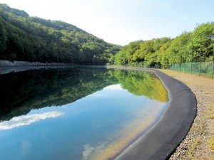
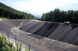
The first double liner with two geomembranes was constructed in June 1974 and has been in continuous service since then. The double-lined structure is a water reservoir located in Pont-de-Claix, near Grenoble in southeastern France. The geotechnical study showed that strict leakage control was necessary to avoid a risk of slope instability. A double liner was designed and constructed—a new concept at the time.
This article is intended to contribute to the history of the geosynthetics discipline by presenting the development of a concept—the double liner—that is an essential feature of a number of structures containing liquids and waste, and by describing the construction and performance of this landmark reservoir, the first structure constructed using a double liner with two geomembranes. This article will also serve as a reference document for tests performed in the future when the geomembrane is removed.
Relevant aspects of design and construction (continued from Part 1)
Primary liner
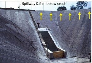
The primary liner is a 1.5mm-thick butyl rubber geomembrane. The geomembrane is unreinforced except that its top part (Figure 3), about 2m measured along the slope and in the anchor trench, is reinforced with a scrim (i.e., a light woven fabric inside the geomembrane). No information is available on the scrim. Typical scrim used in the 1970s in butyl rubber geomembranes had a mass per unit area of approximately 100g/m2 and a tensile strength of the order of 20kN/m with a maximum strain of 15–20%.
The butyl rubber geomembrane rolls were made in the U.K. using butyl polymer from Esso Butyl. The butyl rubber geomembrane panels (approximately 1200m2) were prefabricated in a factory in France by Fipec, a sister company of Butyl Products Ltd., a U.K. company. In particular, the reinforced strip was seamed to the rest of the geomembrane in the prefabrication factory. In other words, the horizontal seam between reinforced and unreinforced geomembrane was not made in the field.
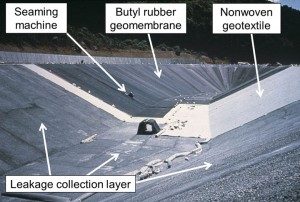
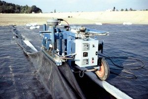
The geomembrane was installed in the summer of 1974 by Fipec on a polyester, needle-punched, nonwoven geotextile (Figure 10). At that time, there was already three years of experience with the use of geotextiles to protect geomembranes. The completed installation can be seen in Figures 2, 3, and 11. The butyl rubber geomembrane and the geotextile are secured in an anchor trench, 0.2m deep by 0.5m wide, located at a 0.5m horizontal distance from the top of the slope.
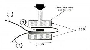
Seaming of the geomembrane was done as shown in Figures 12 and 13. The seam between the reinforced geomembrane used at the top of the reservoir slope (Figure 3) and the unreinforced geomembrane was intended to be a double seam done in the prefabrication factory by two successive applications of the jaws on two parallel tapes. This precaution was envisioned because this horizontal seam on the slope was expected to be subjected to high tensile stresses. No available record confirms if this was implemented.
Behavior of the reservoir
Visual observation in 2011
The authors visited the site with A.L. Rollin in September 2011, 37 years after construction. The reservoir was full (i.e., the water level was 1m vertical below the crest) (Figure 14). The reservoir has never been emptied and the portion of butyl rubber geomembrane above water has been continuously exposed since 1974. As indicated above and in Figure 3, the emerged portion of the geomembrane, the only portion of geomembrane visible during the site visit, is reinforced with scrim.
The butyl rubber geomembrane appeared to be in good condition. It did not seem brittle and it did not exhibit visible cracks. Only one hole (about 1cm2) was seen (Figure 15), at the south end of the reservoir, in the horizontal portion of the geomembrane between the top of the slope and the anchor trench. The reinforcing fabric (scrim) was visible at the edge of the hole. No other mechanical damage was observed.
A small piece of unreinforced butyl rubber was taken by A.L. Rollin from the edge of a seam. This piece was approximately 2cm long and 2mm wide. This unreinforced butyl rubber was probably part of the unvulcanized tape used to make the seam. When this piece of butyl rubber was pulled by hand, it exhibited a strain of several hundred percent. Clearly the butyl rubber (at least the unreinforced one, used for the seams) had retained its extensibility after 37 years of exposure.
The entire upper face of the butyl rubber was covered with a very fine black oily material that stained the fingers and could be removed from the fingers only with vigorous washing with soap. This material may be a carbon compound that migrated to the geomembrane surface. No discoloration of the geomembrane was observed; however, it is possible that the geomembrane would appear discolored if it were washed.
Sporadic traces of another black material were seen on the geomembrane. This was tentatively attributed to bitumen possibly splashed during stabilization of the perimeter gravel road.
The seams appeared to be strong. They could not be peeled by hand. The reinforcing scrim was visible at the edge of each geomembrane strip, because the seams were not covered with a cap strip. However, inspection of the geomembrane did not show the type of blistering or delamination (at least in the emerged part of the geomembrane) that has been observed in the past with other types of reinforced geomembranes having scrim visible at the edge. (Visible scrim tends to wick water into the geomembrane.)
As seen in Figure 12, a 5cm-wide portion of geomembrane is heated at 200 C even though it is not actually seamed. There was some concern that this heating could cause premature ageing of a 5cm-wide zone of butyl rubber geomembrane parallel to the seams. This type of problem was not observed on the visible portion of the geomembrane.
No wrinkles due to thermal expansion were observed. The only wrinkles of the geomembrane were seen at the end of construction (Figure 3). They apparently resulted from installation and were due to the complex geometry of the reservoir.
Footprints from various animals including birds were observed, but they were not associated with mechanical damage of the geomembrane. No mechanical damage by the wind was to be expected since the reservoir has never been empty and the site is protected from wind by the east slope and the forest.
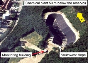
The authors also visited the monitoring building (Figure 2). The outlets of the two leakage removal pipes were completely dry.
Comments on butyl rubber
geomembrane durability
Today, the use of butyl rubber geomembranes is significantly reduced compared to what it was in the 1970s due to high cost and difficult seaming. Another elastomeric geomembrane, EPDM, is used today because it has better durability than butyl rubber. However, as shown in this article, the durability of butyl rubber can be remarkable.
Butyl rubber ages more rapidly when it is elongated because the double bonds of its molecular chains then become more accessible to ozone atoms. This explains why reinforced butyl rubber geomembranes age less rapidly than nonreinforced butyl rubber geomembranes.
The butyl rubber geomembrane supplier had recommended the use of reinforced geomembrane at the top of the side slopes to ensure better durability. In retrospect, it appears that the supplier’s recommendation was appropriate. It is possible that a nonreinforced butyl rubber geomembrane at the reservoir’s crest would have aged more rapidly. It is also possible that, if the reservoir had been emptied many times, the geomembrane would have aged more, because of more stresses and more exposure to sun and wind. The nonreinforced part of the geomembrane (which may tend to age faster) was almost continuously under water and was therefore protected from direct exposure to sunlight and weather.
Leakage monitoring
The reservoir has been monitored by the plant personnel since the end of construction. Some water was conveyed to the monitoring building by the leakage removal pipes for 10 days when the reservoir was filled in 1974. This was likely due to condensation of water vapor entrapped in the leakage detection layer during construction (a phenomenon observed in monitoring leakage detection systems in landfills). No more water was collected until 2004, 30 years after construction, when a trickle of water appeared in the monitoring building at the outlet of the west leakage removal pipe, indicating that the leak was on the west half of the reservoir. The leak location was found because bubbles appeared at the surface of the water. The leak was located at a depth of about 5m, very close to the concrete water intake structure, which is not surprising because this is a typical location for high tensile stresses in the geomembrane. The leak was inspected by divers who determined that it was located at the closest seam to the concrete structure.

The leak was repaired under water. A patch made of a piece of unidentified geomembrane was glued to the geomembrane liner by divers. According to the maintenance staff, it is possible that the patch does not adhere strongly to the geomembrane. However, leakage was stopped, and no additional leakage has been detected since 2004.
Tests on the geomembrane
It was not possible to take geomembrane samples to test for the following reasons:
- the geomembrane is under tension and cutting samples could trigger tearing of the geomembrane;
- sample holes would be difficult to patch, because it is difficult to seam aged butyl rubber;
- it is not easy to find funding for tests on a geomembrane that is no longer widely used.
Therefore, it has not been possible to carry out the test program that had been prepared. The information provided in this article will be useful, however, for planning tests when the liner is removed at the end of its service life.

Conclusion
This case history shows that a reinforced butyl rubber geomembrane can last 40 years when it is exposed in a temperate climate with hot summers, which is remarkable. Ironically, butyl rubber geomembranes are much less used today than they were in the 1970s in part because they were thought to have insufficient durability. It should be noted that several types of modern geomembranes would last longer than 40 years under the same conditions, which is encouraging. This reservoir can be considered a historic landmark of the geosynthetic discipline for the following reasons:
- it is the first double
geomembrane liner; - state-of-the-art design and
testing were done four decades ago; - the performance of the geomembrane has been remarkable.
Acknowledgments
The cooperation of the management and staff of Perstorp, the owner of the site, is gratefully acknowledged. The authors are grateful to R.B. Wallace, I.D. Peggs, A.L. Rollin, and P. Barker for their reviews and to F. Delorme and A. Hayes for providing valuable information.
J.P. Giroud, Ph.D., is a consulting engineer, a past-president of the International Geosynthetics Society, and a member of the U.S. National Academy of Engineering.J.P. Gourc, Ph.D., professor
of geotechnical engineering until 2012, is currently professor emeritus at Grenoble University.
All figures courtesy of the authors
Figures 1 and 4–9 appeared in Part 1