 TEXTILES.ORG

Construction of the new Nowolazurowa Street tunnel in western Warsaw, Poland.
By Jakub Bryk
Introduction
Nowolazurowa is a new road in the western part of Warsaw, Poland, built to connect burgeoning suburbs with the highway ring road S8. It was designed as a two-roadway, dual-lane artery with sidewalks and bicycle lanes. The section described in this article is 2.5km long and 30m wide, laid out in a developed urban area.
The road cuts across a major railway connecting two large Polish cities—Warsaw and Poznań. This railroad also happens to be a part of the international connection between Moscow and Berlin. A new underpass tunnel had to be constructed through the railway embankment.
Challenging schedule
The rail administrator’s primary concerns were safety and continuation of traffic on the track above the road construction. The construction of the underpass road was planned and budgeted for 2012.
However, in June 2012 Poland and Ukraine co-hosted the 14th European soccer championships. Poland was expecting increased passenger rail traffic and no interruption to public transportation during that time would be acceptable. Therefore, scheduling concerns were critical to the selection of the construction method. Effectively, the underpass structure had to be constructed in less than 14 days because the rail administration would not permit longer track closure.
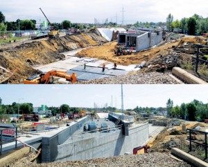
To complete the tunnel in that two-week window, it was decided that a tunnel structure would be prefabricated adjacent to the railroad embankment and then repositioned into its final location during the permitted rail closure, after the final tournament match. A 60m-long, 27m-wide, 6m-tall concrete structure was designed and constructed in late spring/early summer of 2012. The plan called for the entire assembly, which weighed 10,500 (metric) tons, to be pushed 63m into the railroad embankment.
Sliding tunnel concept
The tunnel sliding procedure was designed according to Freyssinet’s Autoripage® technique. According to the technique, the structure would first be built adjacent to the track. Then with the rail blockade secured and the track and embankment removed, the newly exposed ground would be leveled. At that point, the structure could be slid from its constructed position beside the tracks into its final position.
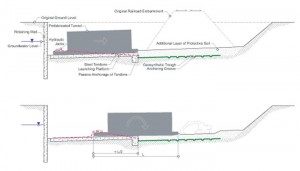
Before the concrete structure was built, a retaining wall was required to provide passive resistance to the tunnel. The site next to the railway embankment would then be dewatered and excavated. The reinforced concrete launching platform was constructed with guides and steel tendons anchored to the front end of the slab. The 10,000-ton tunnel structure would then be constructed on the launching slab. Steel strands would be tied to nine massive hydraulic jacks installed at the back end of the tunnel (Figure 1). The jacks were designed to pull on the strands causing the tunnel to move forward, initially over the launching slab and eventually over soil subgrade in front of the slab. A system of pipes was to be installed in the tunnel’s floor to inject bentonite slurry to reduce friction.
All enabling works and prefabrication of the tunnel were completed in four months in the spring/summer of 2012.
Challenging site conditions
While approaching the day of final sliding operation, the contractor became concerned about the watertightness of the structure. The original design did not include external waterproofing. The concrete structure was assumed to remain watertight throughout the sliding operation and further use. However, during the prefabrication of the tunnel structure it became apparent that groundwater level in the excavation was higher than expected. The tunnel also was constructed on an accelerated schedule, with the final batches of concrete poured shortly before the sliding operation. It was likely that cracks in the concrete would open up during sliding, allowing in water seepage.
Four weeks prior to the scheduled sliding of the structure, a decision was made to design an additional tunnel waterproofing system. The system needed to handle up to 4m of head pressure. Two thousand square meters of waterproofing were to be installed in less than three days to maintain the schedule. Traditional waterproofing below the foundation slab was not considered, because it would wear through during the sliding stage.
Geosynthetic trough
After considering various solutions, a watertight geosynthetic trough beneath the final grade of the tunnel was designed and constructed. Geosynthetics seemed to be the only materials that could have been installed quickly to provide instantaneous protection to the structure. The ease of extending the bottom liner onto the walls made geosynthetics the best choice for this project.
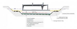
After the rail embankment was removed, the soil foundation level was over-excavated by 60–100cm and a geosynthetic clay liner was installed at the base. Additional GCL flaps were secured and folded along the edges of the excavation, covered with temporary woven geotextile, and backfilled with soil (Figure 2). This extra GCL along the edges allowed the extension of waterproofing onto the walls of the tunnel once it was placed in final position.
The GCL was covered with a textured 1mm-thick HDPE geomembrane. Geomembrane panel seams were only overlapped, instead of welded, to allow expedited installation. A drainage geocomposite was installed above the geomembrane. The drainage composite served two functions:
- to allow detection and recovery of potential leakage.
- to collect any surface runoff water that might overflow from the road drainage system during intense storm events.
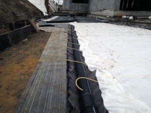
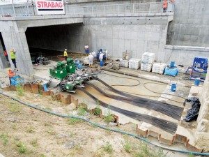
An innovative geocomposite comprising an array of mini-pipes laid out on drainage geotextile and capped with a nonwoven geotextile filter was selected. The mini-pipe drainage geocomposite was chosen for its high in-plane flow capacity and high resistance to compressive loads. It also allowed for quick and easy connection to the perforated drainage collection pipes that were installed on top of geomembrane, parallel to the direction of tunnel sliding. The geocomposite was connected to drainage pipes using the manufacturer’s quick connect system.
Geogrid was then placed above the geosynthetics and anchored to the launching slab, below the face of the prefabricated tunnel. The goal was to reinforce the interface between the backfill soil and the geosynthetic materials. It was critical to ensure that the tunnel being pushed toward its final position would slide over the compacted backfill of selected granular soil or, that in a worst-case scenario, the backfill soil would shear internally. In the event that a layer of compacted soil would break free and slide along with the tunnel on the surface of geosynthetics, the geosynthetics would be damaged and no longer serve as an effective barrier. To prevent this, the interface strength had to be higher than internal shear strength of the compacted fill. The geogrid installed at the interface was intended to improve interface friction and to reduce the shear stress through introduction of tensile reinforcement.
Meeting this interface strength requirement turned out to be more difficult than expected. Due to the large sliding distance (more than 60m) and the weight of the structure, the shear stress at the geosynthetic assembly interface was large, larger than any geogrid anchored at one end could handle. The interface integrity was particularly important in the second half of the sliding distance. Because the launching slab was constructed with a small upward slope, the tunnel remained resting on the launching slab until it moved approximately half of the distance. Once there, it was tilted forward over the edge of the slab, and a large portion of the tunnel’s weight was suddenly applied to the soil on top of the geosynthetic trough. To provide additional anchorage and to shorten the distance over which the geosynthetics were tensioned, an additional anchoring groove was excavated in the subgrade every 4m. The grooves, 15cm-deep and 30cm-wide, provided enough anchorage to ensure required interface shear strength (Figure 1).
Construction & sliding process
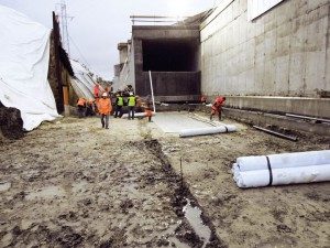
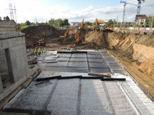
Installation of geosynthetics and placing soil backfill were carried out continuously, day and night.
The weather proved to be the biggest obstacle. Throughout initial prefabrication and enabling works, the weather was unexpectedly hot, preventing the contractor from placing concrete and removing formwork during daytime. The majority of the work had to be done during night shifts. As it happened, when the final sliding operation was about to commence, it cooled off and rained throughout the first two days of operation, when the bulk of the geosynthetics were to be installed. Each time the soil was compacted to specification and leveled it received a 30-minute downpour, which was enough to ruin the surface. The drizzle between the storms was also problematic. Under normal circumstances it would be reasonable to delay the earthworks and wait for the weather to improve. However, with only the 14 days allowed by the railroad administration, the earthworks contractor had no choice but to continue struggling under unfavorable conditions. The first two days were the only rainy ones in the 14-day tunnel installation campaign.
The 2,000m2 geosynthetic trough was completed in three days, slightly behind the assumed schedule and definitely not without effort. The geosynthetics were backfilled with an additional 50-cm layer of soil above the ultimate foundation level of the tunnel. This additional soil was later used to control the vertical alignment of the tunnel being pushed. When the concept of geosynthetic trough was first conceived, the specialist sliding contractor expressed concern about compressibility of the subgrade. The contractor argued that in situ, preconsolidated soil provides a better foundation for tunnel sliding than any prepared ground might. The dispute was settled by the general contractor who was ready to take the risk, with the thickness of the additional soil layer on top of the soil foundation level increased for additional safety.
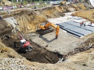
The sliding operation took place on Aug. 17, 2012, and lasted 16 hours before the tunnel was moved the full 63m. While the tunnel was being pushed, three excavators were removing extra soil in front of the tunnel to control vertical alignment. Initial fears about the compressibility of the soil proved unfounded and the tunnel was installed to a 5-cm tolerance.
To stand on the moving structure felt like being in an earthquake, especially during the initial phase of sliding. The leaping movement of the tunnel was due to the length and elasticity of the steel tendons. In the early stages of the operation, long tendons were first tensioned to a critical point when the frictional resistance below the tunnel was exceeded and the tunnel moved rapidly. As the length of the tendons was reduced, the movement became steadier.
For the most part, the sliding operation proceeded smoothly. In the initial phase the tunnel was resting on the launching slab and there was no need to worry about vertical alignment. Once the structure passed the critical point and leaned forward, resting on the subgrade, limited soil bulging was observed in front of the tunnel and the procedure continued undisturbed. The team became increasingly confident that the operation was progressing successfully.
Late at night, just a couple of meters before the final position, the geosynthetics appeared on the surface of soil, in front of the tunnel. At that point, nothing could have been done to remedy it, and the sliding operation continued. The geosynthetics were excavated and inspected after the rail traffic had been restored. The excavations revealed that in the final stage of the operation all geosynthetics experienced uplift in the soil and were damaged, though not completely torn. A potential explanation for this phenomenon is rotational soil failure.
The original in situ soil in the final section of the excavation was a mixture of silt and clay. The surface of this semipermeable soil had a geosynthetic liner cutoff. It is believed consolidation water accumulated in front of the moving structure. Toward the end of the sliding process the tendons were short and less extendable so the tunnel was moving faster. Late at night, then-confident operators wanted to complete the operation as soon as possible. The rate of movement and corresponding stresses were high enough to have caused an undrained response of the soil. Apparently, because of excessive pore water pressures that could not dissipate, the soil below the front of the tunnel sheared and failed rotationally. Luckily this phenomenon was limited to the last few meters of the tunnel. This section had to be excavated anyway to extend the liner longitudinally. All damage was repaired and the liner was extended.
Once the rail traffic had been restored, the extra liner secured on the sides of the tunnel was excavated and extended onto the tunnel walls. The liner was protected with a nonwoven geotextile cushion and backfilled.
By 2014, adjacent sections of the tunnel were completed. Vehicles now routinely drive through the tunnel and no seepage has been observed.
Jakub Bryk is geosynthetics director at Maccaferri Polska and is vice president of the Polish Chapter of IGS (International Geosynthetics Society).
Project Highlights
Construction of Nowolazurowa Street from Salomea Junction to Polczyńska Street
Location
Warsaw, Poland
Client
Miasto Stoleczne Warszawa,
Zarzad Miejskich
Inwestycji Drogowych
(Warsaw municipality)
General contractor
Strabag Sp. z o.o.
Geosynthetic materials
Geomembrane
OBR Geochron
Drainage geocomposite
Afitex Draintube
Geogrid
Tensar TriAx
Other
GCL, woven and
nonwoven geotextiles