TEXTILES.ORG

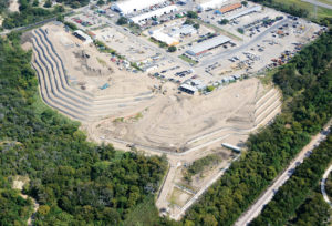
Harold Court East Regional Service Center in Austin, Texas
Introduction
The Harold Court East Regional Service Center in Austin, Texas, is a city-owned multi-purpose facility used primarily for material storage.
The erosion control and other issues at this site included:
- periodic movement of the embankments on the western and southern boundaries of this property.
- the need for permanent slope stabilization.
- a displaced 48-in. stormdrain requiring repair (erosion had eliminated the original outfall).
- potential damage to an existing wastewater main.
Site description
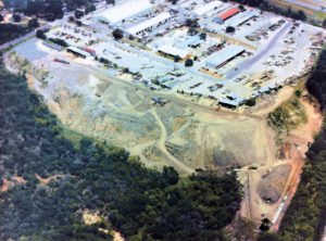
The service center site occupies about 23 acres of a 75-acre tract adjacent to U.S. Highway 183. Outflow from this site contributes to both the Fort Branch Creek and Boggy Creek watersheds. The facility consists of an office building and maintenance sheds, an asphalt parking lot, and an equipment yard.
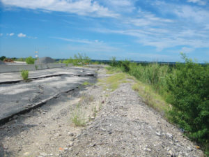
The terrain slopes steeply along the south side of the yard to Boggy Creek and also along the west side to a tributary of Boggy Creek. Vegetation on the site consisted of small trees, grasses, weeds, and thick underbrush.
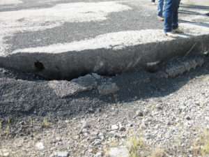
Fill material had been placed along the outside perimeters of the yard. Erosion cracks and drainage channeling were clearly evident along the top edge and the facing of the slopes.
Geotechnical investigations
Eight soil borings were done 15ft to 58ft below the ground surface. Both disturbed and undisturbed soil samples were collected.
The investigation revealed that the asphalt layer varied from 1.5in. to 5in. deep. In some areas, there was a 6.5–9in. base under the asphalt.
Fill material was encountered below the asphalt and the base:
- unclassified brown, light brown, reddish brown, and tan clays, silty clays, and clayey sandy silts.
- small to large limestone rock and gravel, carpet fragments, and asphalt, concrete, wire, and plastic debris.
- alluvial soils consisting of silty clays, silty sandy clays, clayey sands, and silty sands.
- found below the existing fill extending to depths of 15–38ft.
In one boring, gray clayey shale was found at 28–30ft. Groundwater was found at 40ft, 36ft, and 8.5ft. All other boreholes were dry.
Preliminary recommendations
Option 1—Install reinforced concrete cantilever retaining wall around the slopes. The estimated cost for this option was high and deemed not economically feasible.
Option 2—Cutting the slopes back in a series of benches. This option would reduce the size of the yard too much and was discounted.
Option 3—Install concrete riprap over the face of the slope at about 1:5 to 1.0. This option was also considered too costly and cracking and settlement would likely occur.
Option 4—Leave the area as is, using it only as a storage area. But even “as is” would require continuous maintenance and re-grading.
New design
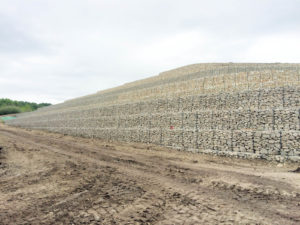
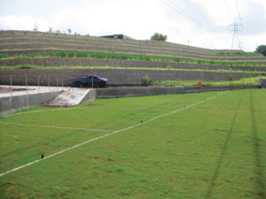
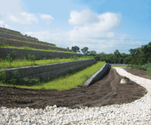
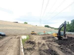
An original design proposed a series of 9ft-tall gabion gravity retaining walls along the steep slope, but in situ soil conditions and other concerns led to a revised design—a series of 9-ft gabion-faced mechanically stabilized earth (MSE) retaining walls separated by vegetated terraces.
The new design included slope controls constructed on the eroding embankment. This measure would prevent further migration of materials while also providing improved worker safety and function for material storage.
The slope controls consist of:
- multiple rows of gabion face MSE walls separated by vegetated terraces.
- a service road to provide access to a proposed bio-filtration pond.
Global stability analysis
At this stage, a global stability analysis was completed, with a factor of safety calculated using the Modified Bishop Method.
Conservative water conditions were modeled because:
- groundwater levels in the borings were highly variable.
- borings were drilled during a period of extreme drought.
A factor of safety 1.3–1.5 is considered acceptable for most embankments.
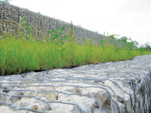
Gabion face MSE wall
The gabion system can be used in soil reinforcement applications such as MSE walls and reinforced soil slopes (RSS). The system includes:
- soft tensile, galvanized, and PVC-coated double twisted steel wire mesh.
- a facing section formed by a pre-assembled back panel and diaphragms to the main fascia unit, thus creating the rectangular shaped cells used for stone confinement. Nonwoven geotextile behind the fascia avoids the migration of backfill into the gabion baskets. Geogrid reinforcement can be used in combination with the gabion fascia unit reinforcing tall MSE wall sections. Fascia, base, tail, and lid are all one continuous panel of mesh, allowing 100% structural continuity of the unit.
- assembly on site, then the fascia unit is filled with suitable gabion stone. Structural backfill can be placed on the soil reinforcement geogrids and compacted.
Construction challenges
Several previously unknown challenges were discovered during construction:
- additional excavation was required.
- borrow materials and removal of waste.
- unstable, saturated slope resulted in several slide failures.
- an undocumented stormwater system.
- underground seeps/springs found during excavation.
- selection of the excavated soil on site, allowing optimized removal and soil dispersal, but still assuring structural backfill use.
- embedded objects found during excavation were removed.
- a drainage system built with 6-in. polyvinyl chloride (PVC) pipes was installed to drain groundwater.
Conclusions
This project helped to improve safety at this site while providing environmental protection, erosion control, and structural stability. The city of Austin is known for its green and environmentally friendly solutions. For this project:
- most of the in situ material was reused.
- installation proceeded even when the quantity of rock was limited in lieu of a larger quantity of structural backfill.
- the city of Austin authorized the use of a mix of limestone rock and crushed concrete as fill.
- one of the few MSE wall systems that is HITEC evaluated. (HITEC—the Highway Innovative Technology Evaluation Center—has served as a first-stop service center to speed the introduction of innovative technologies into the highway marketplace.)
Marco Invernizzi is a managing partner at Alpi Engineering (Rockville, Md.) and consults
for Maccaferri at Main Geo-Construction Sources based in Austin, Texas.
Sachin Mandavkar is a technical manager at Maccaferri Inc.
Anamarie Stralla is the president of Elite Erosion Supply LLC based in Myrtle Beach, S.C.