 TEXTILES.ORG

The tectonic movements caused by earthquakes seriously affect the stability of infrastructure. Highways that pass through seismic fault zones are particularly vulnerable to catastrophic earthquake damage because of their long lines and broad areas. The traditional solutions for these problematic sites in geotechnical engineering have included rigid foundations or structures, embedded retaining structures or buffer trenches, and the placement of ductile engineering fills.
The first solution involves using high-rigidity structures such as thick mats to counterbalance the fault ruptures. The second solution entails installing a diaphragm wall, soil-bentonite mixtures or ground improvement to divert the propagation of shear rupture beyond the boundaries of the target facilities. Alternatively, buffer trenches filled with lightweight expanded polystyrene (EPS) can provide spaces to accommodate fault-induced ground movement. The third measure involves using seismic resilience engineering fills such as geosynthetic reinforced soil (GRS) structures. These structures help to disperse the fault movement over a wider area, which reduces angular distortion at the ground surface and preserves the stability of structures built on top of the ground (Bartlett et al. 2015; Ashtiani et al. 2017; Yang et al. 2020; Rasouli and Fatahi 2020; Chiang et al. 2021; Rasouli and Fatahi 2021).
In highway engineering, the third method has been recognized as the most feasible option with acceptable safety and economic benefits. A geosynthetic reinforced structure has often been used as the seismic resilience engineering fill to spread the fault movement over a wider area. It is a flexible structure made of geosynthetic materials that can effectively absorb earthquake energy, reduce angular distortion on the ground surface, and thus maintain the stability of the overlying structures. According to Chiang et al. (2022), GRS has a higher damping property, making it an ideal choice for embankment construction in earthquake-prone areas.
Background
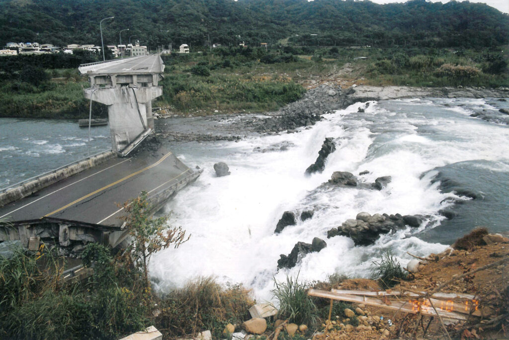
Taiwan sits at the boundary of the active Eurasian and Philippine plates, resulting in more than 50 faults on the island. The number of earthquakes caused by these faults are almost countless, posing a significant threat to people’s lives and property. For example, in 1999, the Chelungpu fault in central Taiwan, one of this island’s most densely populated areas, triggered the deadly 921 Chi-Chi earthquake, which measured 7.3 on the Richter scale. It caused approximately 14,000 fatalities and injuries, severely damaged thousands of infrastructure facilities, and toppled more than 100,000 houses. The earthquake caused a seismic rupture zone nearly 52 miles (85 km) long on the surface from north to south along the foothills of the hilly eastern area. The vertical displacement was about 13.1 to 16.4 feet (4 to 5 m) in this area, as shown in Figure 2, and the horizontal displacement was about 8.2 to 16.4 feet (2.5 to 5 m) in some areas.
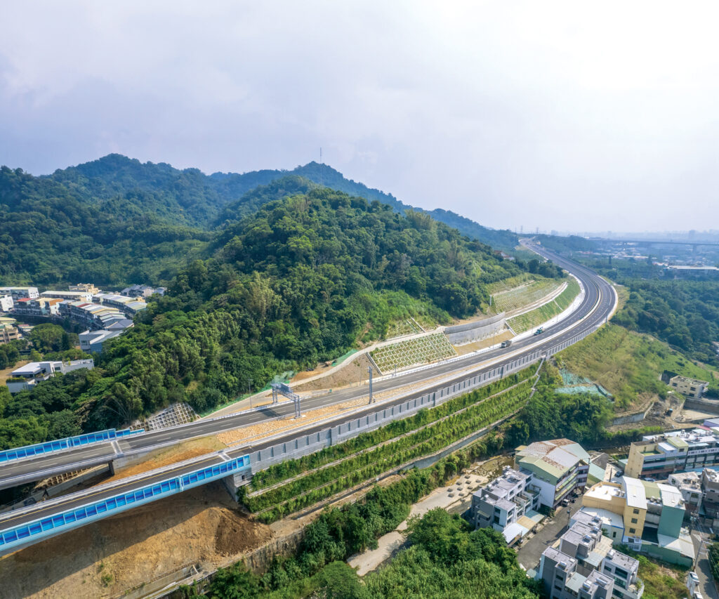
Taichung, the largest city in western Taiwan, has a highly concentrated population and economy. Because of the increasing traffic demand, the highway authority had to quickly promote the extension of National Highway No. 4 to provide convenient transportation services to the metropolitan area and surrounding cities. Although the highway extension inevitably encountered the Chelungpu fault and faced significant difficulties, it still needed to be completed because of the government’s policy. However, by adjusting the highway’s topography, alignments, and service functions, the difficulties were finally minimized to a specific section from Sta. 23k+242 to Sta. 23k+410.
Overview of geosynthetics for fault mitigation
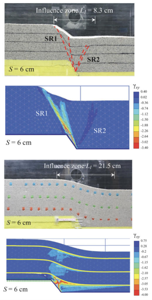
Yang et al. (2020) and Chiang et al. (2021) conducted studies examining fault movements’ impact on GRS foundations. As seen in Figure 3, they used sandbox model tests and finite element numerical simulations to analyze the results. The study found that the reinforcement of the foundations acted as a tension membrane, creating vertical resistance to support the overlying soil and minimizing the impact of surface settlement. Other studies have also verified that an adequately designed GRS structure is effective in seismic resistance and can significantly reduce damage caused by fault movement (Bray 2001; Ardah et al. 2018; Chiang et al. 2021).
Based on the numerical results presented in Figure 3, when the fault movement increases, it generates a significant shear force at the bottom of the GRS structure. However, reinforcement can effectively impede the development of the shear zone, thereby preventing the shear plane from reaching the surface and causing surface rupture. The reinforcement reduces the angular distortion by an average of 60% at the ground surface. Such reinforced earth mechanism can be identified as the shear rupture interception effect. Because of this interception effect, the intense shear strain develops horizontally and extends along the bottom reinforcement layer. The initiated shear strain reduces with the increased distance from the fault tip, indicating that the energy of fault movement is progressively dissipated by the resistance provided by the soil-reinforcement interaction. However, relevant studies have also noted that reinforcement pullout in the top reinforcement layer could occur in the case of short reinforcement. Because of the effect of reinforcement pullout, it is very likely that the shear rupture will be transmitted upward and passed through one end of the reinforcements due to the fault movement. Secondary settlement at the ground surface will be initiated through the end of the reinforcement, indicating that the verification of the pullout resistance of the reinforcement is essential (Chiang et al. 2021).
Project considerations: Safety, practicability and sustainability
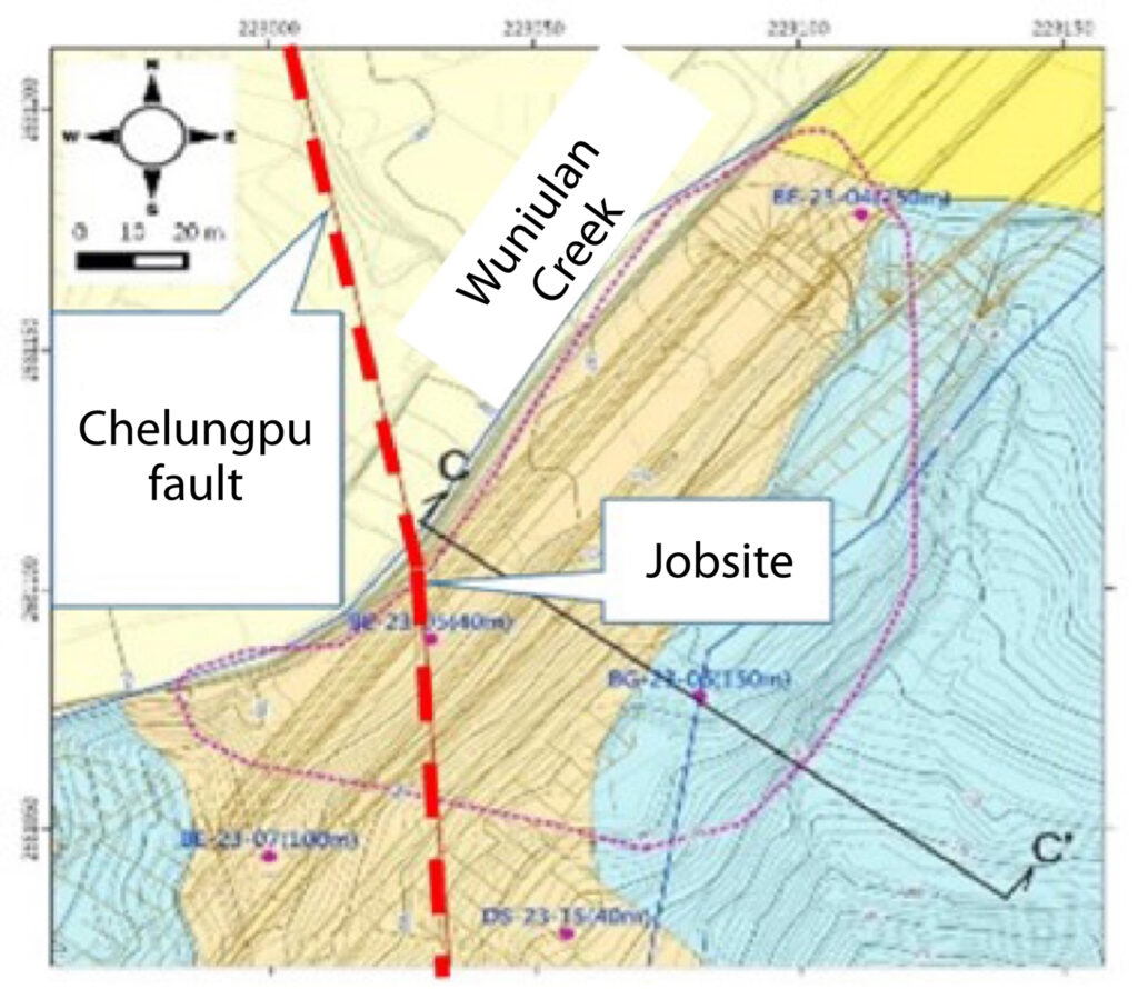
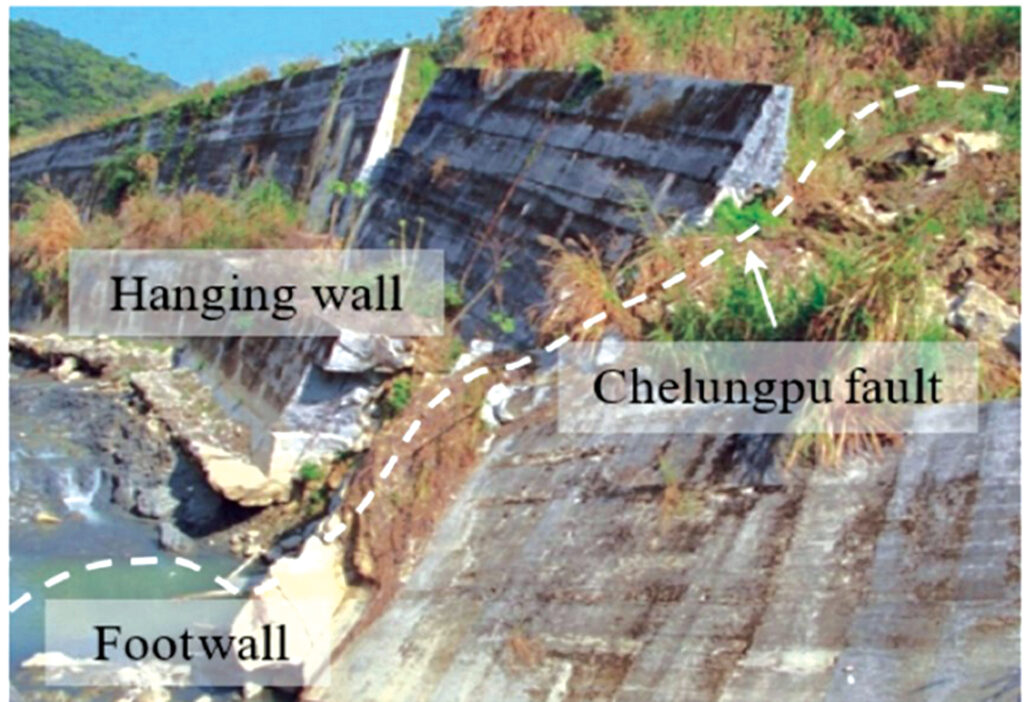
As shown in Figure 4, the surface fracture zone intersects with the designed highway at an angle of about 60 degrees, and the surface rupture caused by the hanging wall on the site was relatively moved up about 9.8 feet (3 m). In addition, historical evidence also indicated that there had been serious fault misalignment, which resulted in severe damage to the nearby reinforced concrete revetments of Wuniulan Creek (Figure 5). Because of the severe impact of the fault, if a similar movement occurs again, it will undoubtedly cause severe damage to the structure of this section. Therefore, the design strategy of this project needed to consider the earthquake-resistant requirements of the structure in this area to ensure the necessary safety. Also, well-organized emergency countermeasures for damage rehabilitation and traffic restoration must be available if a disaster occurs.
The case presented herein runs through the hilly area of the foothills region in western Taiwan. The surface terrain changes significantly, with elevation along the route fluctuating between 984 to 1,476 feet (300 and 450 m). The toe at the west slope of the highway is close to Wuniulan Creek. The east side of the highway is a steep slope consisting of debris formation and only allows for a very narrow proximity for construction.
The design elevation in this section had to be raised 65.6 feet (20 m) from the ground to ensure that the highway alignment matched the slope of the adjacent tunnel and the geometry arrangement at the tunnel’s entrance. Consequently, retaining structures were necessary to ensure safe support for the embankment.
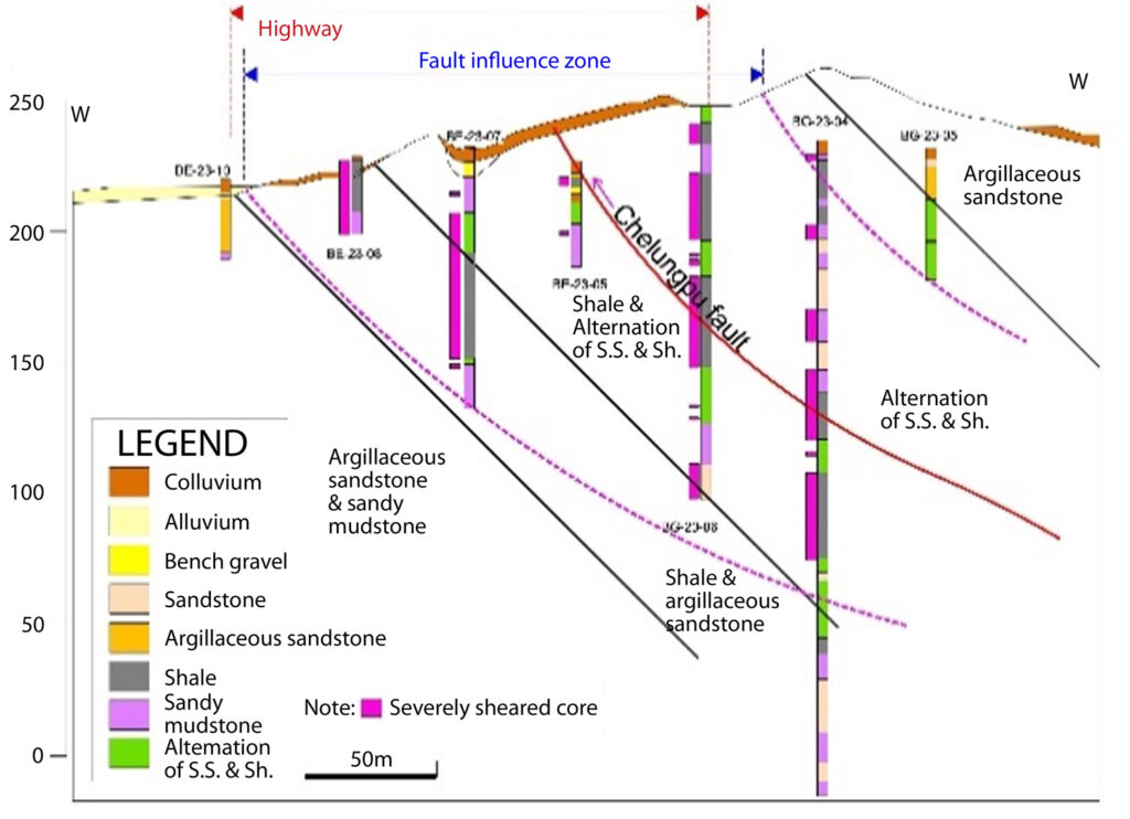
As shown in Figure 6, based on the site investigation, the shallow geological formations at the site consist of colluvium and gravel with poor engineering properties. Bedrock below the site consists of shale, sandy mudstone and alternate layers of sandstone and shale with well-developed shear fractures attributed to the Chelungpu fault. The strength of rock mass is poor due to these fractures.
In summary, the planning and design needed to consider the following factors for this project: narrow site proximity, high embankment, significant differential deformation due to fault movement, the need for timely repair of possible earthquake damage, and the government’ policy for sustainable responsibility.
The designer decided to adopt a geosynthetic reinforced structure in this section to build a 551.2-foot-long (168-m) embankment. The slope near Wuniulan Creek was shaped as a steep slope to solve the problem of narrow proximity at the site. In addition, the design of the GRS embankment could reuse a large amount of excavated material from the adjacent No. 3 tunnel near the site. Doing so dramatically benefited the project by reducing the output transportation of unwanted earth materials and saving shipping costs. It was also more in line with the highest principle of energy conservation, carbon reduction and sustainable development of the project.
Analysis and design
Stability analysis
The static stability analysis of the GRS embankment should first consider the safety of external stability under various conditions such as normal, seismic and storm, including sliding, overturning and bearing capacity. For overall slope stability, the SLIDE 6.0 program was used to analyze the safety factor of slope stability. It is a 2D limit equilibrium program for evaluating the safety factor or probability of soil or rock slope stability failure. It analyzes the stability of slip surfaces using vertical slice or non-vertical slice limit equilibrium methods. The internal stability analysis, including the safety of geogrid pullout and tensile strength, was also confirmed. Based on the analyses, the design scheme and configuration of the GRS embankment and the effective embedded length and spacing of the geogrid were determined.
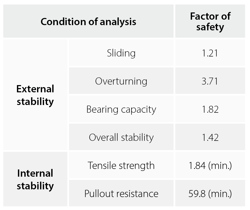
The seismic coefficient of dynamic analysis was based on the Code for Seismic Design of Highway Bridges issued by the Ministry of Transportation and Communication (MOTC 2018). The applied horizontal seismic coefficient (kh) was 0.182, and the vertical seismic coefficient (kv) was 0.091. The seismic analysis results are shown in Table 1, indicating that the designed GRS embankment was stable under all conditions, and all safety factor values met the code requirements. In addition, the analysis also should consider the emergency backfill to repair the surface rupture in case of fault movement. The weight of the additional backfill has been included in the study to ensure the safety of the GRS embankment. Detailed results and discussions are presented elsewhere and will not be given herein (Chang et al. 2022).
GRS design
1. Foundation improvement
Because the GRS embankment is located on the colluvium with poor engineering properties, its bearing capacity needed to be improved. In addition, restraining the fault zone displacement from the foundation would achieve a better reinforcement effect (Chiang et al. 2022). Therefore, the weak soil under the embankment was replaced by a GRS foundation. It was done by removing the underlain weak shallow colluvium and replacing it with the GRS foundation.
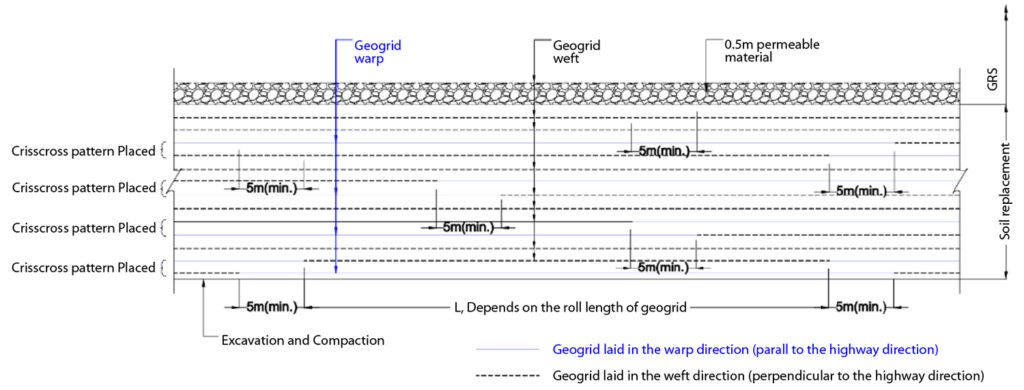
In Figure 7, ACEGrid® GG150-I geogrids were arranged in a crisscross pattern. These geogrids have an ultimate tensile strength of 10,243.90 lbs/ft (150 kN/m) and are made of high-tenacity, multifilament polyester yarns. They are coated with a durable polymer for low creep behavior, high tensile modulus, and longevity (ACE Geosynthetics 2024). Two geogrid layers were laid in the warp direction with a vertical spacing of 2.0 feet (0.6 m) perpendicular to the highway direction. Then a layer of geogrid was laid in the direction of parallel latitude (parallel to the highway direction) at a space of 1 foot (0.3 m). Backfill for the GRS foundation was compacted to at least 95% of the modified Proctor maximum dry density. The total length of the GRS foundation was about 459.3 feet (140 m), and the replaced depth reached the gravel stratum or bedrock with sound engineering properties ranging from 9.8 to 16.4 feet (3 to 5 m).
2. GRS embankment
Figure 8 displays the schematic design of the GRS embankment. The construction was completed in three stages using ACEGrid® GG150-I wrap-around facing setback and an inclined ratio of 1:0.2 (vertical : horizontal). Each stage was 16.4 feet (5 m) high, and the width of the step-back platform was 4.9 feet (1.5 m). The GRS embankment was built to support highways, meaning the geogrid configurations had to meet the highest requirements for function and safety.
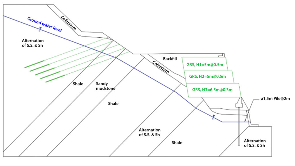
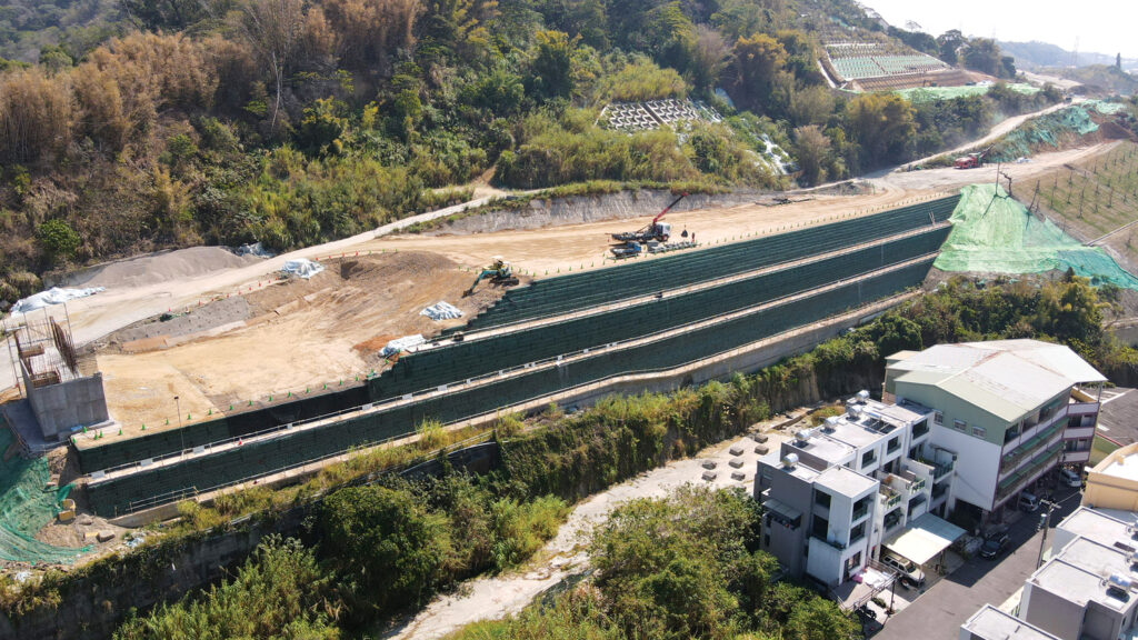
The geogrid was placed with a vertical spacing of 0.9 feet (0.3 m) at the lowest stage and 1.6 feet (0.5 m) for the other two higher stages. The geogrids were embedded at different lengths, with the lower layer being 65.6 feet (20 m), the middle layer being 61.7 feet (18.8 m), and the upper layer being 55.8 feet (17 m) as shown in Figure 9. Drainage boards, geotextile filters, and porous gravels were installed in each stage to intercept rainfall infiltration or seepage effectively. In addition, stacked soil-filled and hydro-seeded sandbags (ACESandbag™ EC) were used to protect the slope face and promote a natural green aesthetic landscape.
The fill material was the excavated materials from the nearby tunnel. It was compacted to more than 95% of the modified Proctor maximum dry density. In addition, permeable material, 1.6 feet (0.5 m) thick, and high-density polyethylene (HDPE) drainage pipes were installed at the bottom of each stage of the GRS embankment to improve the overall drainage efficiency and safety for seepage and heavy rainfall. The GRS embankment was designed with geobags facing, which were attached to the embankment using the geogrid wraparound method. Geobags contain formulated seeds, fertilizer and organic soil that facilitate vegetation growing and greening the surface of the embankment (Sinotech Engineering Consultants Ltd. 2017).
3. Protections for adjacent slopes
The site materials surrounding the embankment are weak colluvium and fractured bedrock. The designer decided to build a permanent pile-supported retaining structure at the toe of the GRS embankment adjacent to Wuniulan Creek. The diameter of the pile used was 4.9 feet (1.5 m) and closely spaced 6.6 feet (2 m) to ensure the stability of the toe of the huge embankment. The pile-supported retaining structure also protects the safety of the existing riverbank of Wuniulan Creek.
For safety, the upper slope was first shaped to a gentle slope of 1:2.5 (vertical : horizontal). It was then covered by reinforced concrete lattice girders, plus 44 tons (40 tonnes) of preloaded anchors 82 feet (25 m) in length, spaced 8.2 feet (2.5 m) in the X and Y direction (Figure 10). The protection system has been verified to fulfill all code safety requirements under various conditions, such as normal, rainstorms and earthquakes.
Contributions of GRS for sustainability
The conclusion of UN Climate Change Conference (UNFCCC COP28), called for reducing the consumption and production of fossil fuels to reach net zero by or around 2050. The Sustainable Development Goals (SDGs) are the blueprint to achieve a better and more sustainable future for all. In the UN’s 2030 Agenda for Sustainable Development, sustainable transport and disaster risk reduction are mainstreamed across several SDGs and targets, especially those related to energy, economic growth, infrastructure, and cities and human settlements (UN 2023).
This case study exemplifies enhanced engineering resilience to span a fault zone, aligning with SDG 9. The use of GRS embankment provided sustainable transport and contributed to energy savings and carbon reduction, relating to SDGs 11 and 13.
A comparison revealed that using a traditional cantilever reinforced concrete wall would emit approximately three times more carbon than the installed GRS embankment.
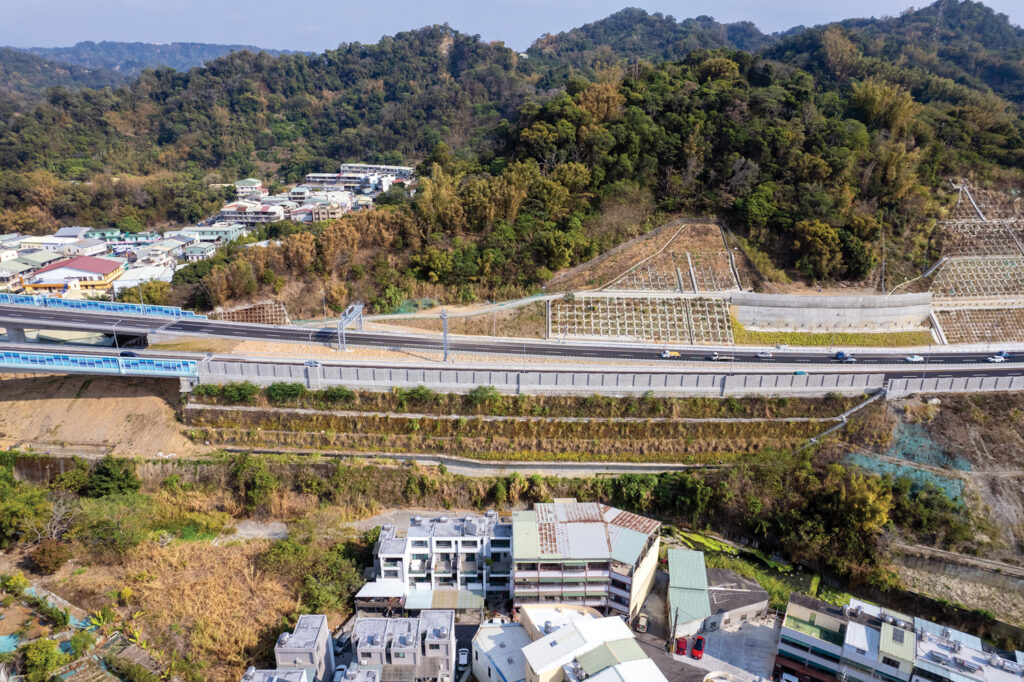
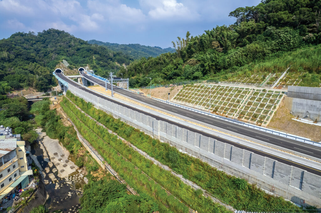
Additionally, the project applied a vegetative wraparound facing for slope stability and aesthetic green landscaping, minimizing the impact on habitats and benefiting the surrounding terrestrial ecosystems and halting biodiversity loss, which echoes SDG 15 (Figure 11). As for COP28’s appeal for energy conservation, carbon reduction and sustainable development, the performance of this project has made a significant contribution.
Conclusion
Fault zones are a significant concern for highway safety. Compared to traditional reinforced concrete structures, geosynthetic reinforced structures with reliable resilience are less expensive and can effectively minimize the risk of earthquake disasters. In the presented case, building the GRS embankment reused a large amount of excavated materials from the construction of nearby tunnels, significantly reducing the time and cost of disposing and transporting these unwanted materials. Such a distinguished approach has made the project substantially comply with the principles of energy savings and carbon reduction benefits. The use of GRS meets all engineering requirements and conforms with several UN Sustainable Development Goals, which are a significant step toward a sustainable solution for earthquake-prone areas.
Zoe Lin is technical manager at ACE Geosynthetics, Taiwan (R.O.C.).
Amy Tang is vice president at ACE Geosynthetics, Taiwan (R.O.C.).
All figures courtesy of ACE Geosynthetics.
References
Ardah, A., Abu-Farsakh, M. Y., and Voyiadjis, G. Z. (2018). “Numerical evaluation of the effect of differential settlement on the performance of GRS-IBS.” Geosynthetics International, 25(4), 427–441.
ACE Geosynthetics (2024). https://www.geoace.com/products/Geogrids/ACEGrid%C2%AE-GG
Ashtiani, M., Ghalandarzadeh, A., Mahdavi, M., and Hedayati, M. (2018). “Centrifuge modeling of geotechnical mitigation measures for shallow foundations subjected to reverse faulting.” Canadian Geotechnical J. 55(8), 1130–1143.
Bartlett, S. F., Lingwall, B. N., and Vaslestad, J., (2015). “Methods of protecting buried pipelines and culverts in transportation infrastructure using EPS geofoam.” Geotextiles and Geomembranes, (43)5, 450–461.
Bray, J. D. (2001). “Developing mitigation measures for the hazards associated with earthquake surface fault rupture.” A Workshop on Seismic Fault-Induced Failures–Possible Remedies for Damage to Urban Facilities, Japan Society for Promotion of Science, University of Tokyo, Japan.
Chang, C. T., Huang, H. C., Wang, Y. K., and Lee, M. C. (2022). “Applications of geosynthetic reinforced soil wall for embankment slopes of Taiwan’s freeway.” Proc. GeoAsia 7, Taiwan.
Chiang, J., Yang, K. H., Chan, Y. H., and Yuan, C. L. (2021). “Finite element analysis and design method of geosynthetic-reinforced soil foundation subjected to normal fault movement.” Computers and Geotechnics 139, 1–26.
Chiang, J., Yang, K. H., Yuan, C. L., and Lin M. L. (2022). “Mitigation of fault movement disasters by flexible reinforced earth method – engineering practice and mechanics research.” NTUCE Newsletter. 156 (in Chinese).
Ministry of Transportation and Communication. (2018). Code for seismic design of highway Bridges, MOTC (in Chinese).
Rasouli, H., and Fatahi, B. (2020). “Geofoam blocks to protect buried pipelines subjected to strike-slip fault rupture.” Geotextiles and Geomembranes, 48(3), 257–274.
Rasouli, H., and Fatahi, B. (2021). “Geosynthetics reinforced interposed layer to protect structures on deep foundations against strike-slip fault rupture.” Geotextiles and Geomembranes 49(3), 722–736.
Sinotech Engineering Consultants Ltd. (2017). “Design and analyses of reinforced earth structure for sections of Wuniulan Creek.” (in Chinese).
UN. (2023). https://sdgs.un.org/topics/sustainable-transport.
Yang, K. H., Chiang, J., Lai, J. H., and Lin, M. L. (2020). “Performance of geosynthetic-reinforced soil foundations across a normal fault.” Geotextiles and Geomembranes 48(3), 357–373.
SIDEBAR: Project Highlights
EXTENSION PROJECT OF NATIONAL HIGHWAY NO. 4 STATIONS OF 23K+242 TO 23K+410
OWNER: Freeway Bureau, MOTC
LOCATION: Taichung, Taiwan
CONTRACTOR: Fortune6446 Construction Co., Ltd.
ENGINEER: Sinotech Engineering Consultants, Ltd.
GEOSYNTHETICS PRODUCTS: ACEGrid® GG150-I
GEOSYNTHETICS MANUFACTURER: ACE Geosynthetics