 TEXTILES.ORG

For the past 17 years, the Geosynthetic Institute (GSI) has been accumulating data on failures of geosynthetic reinforced mechanically stabilized earth (MSE) retaining walls. We presently have 320 cases, of which 201 (63%) have been caused in whole or part by water within, or adjacent to, the reinforced soil zone. We sincerely hope that our past writings and webinars are helping to correct, or at least minimize, this unfortunate situation from continuing into the future. Yet, there is one issue that has been, and continues to be, a serious omission in the design and construction of such walls. That is the lack of a geotextile filter between fine-grained backfill soils and gravel drainage layers in the reinforced soil zone.
To place fine-grained backfill soils (note that 232 of the 320 failures [72%] used silt, clayey silt, silty clay or clay soils) against gravel drainage layers with water moving from the fine to coarse soils is a fundamental violation of basic soil filtration concepts. Shown first by Terzaghi in the 1930s, followed by Bertram in the 1940s and then by the U.S. Army Corps of Engineers in the 1950s, soil filter design using sand as the filter material is a well-established practice in geotechnical engineering.
There have been countless researchers and practitioners since then (e.g., every geotechnical engineering professor worldwide) showing that the water will mobilize fine-grained soil particles to migrate into the gravel’s voids rendering its permeability greatly reduced, eventually becoming that of the fine-grained soil itself. Thus, the gravel will no longer provide its intended purpose of drainage. This is not a hypothesis; it is a known fact and can easily be reproduced in any soils or hydraulics laboratory.
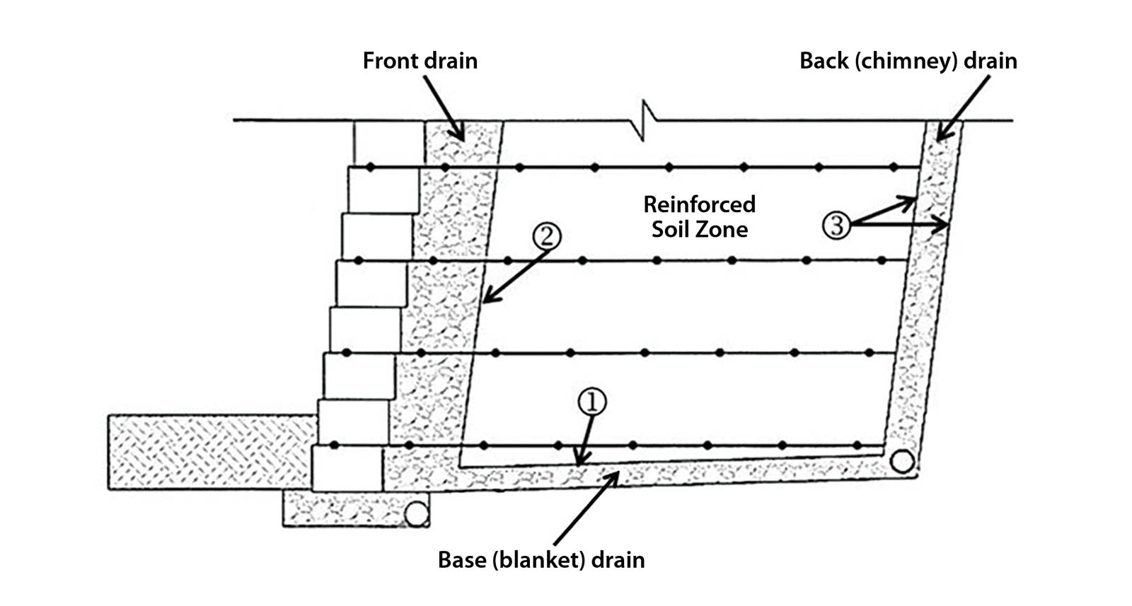
Clearly needed in such cases is a filtration medium, either sand or geotextile, of which the latter is easy to place, more economical and readily available. Regarding geotextile filtration design, our keyword literature search shows that there are 104 papers available on the topic. In this regard, see GSI White Paper #35 for a review of both sand and geotextile filter design. That said and with regard to MSE walls, there are three distinct locations within the typical MSE wall cross section that are deficient in this regard. Their locations are shown on Figure 1.
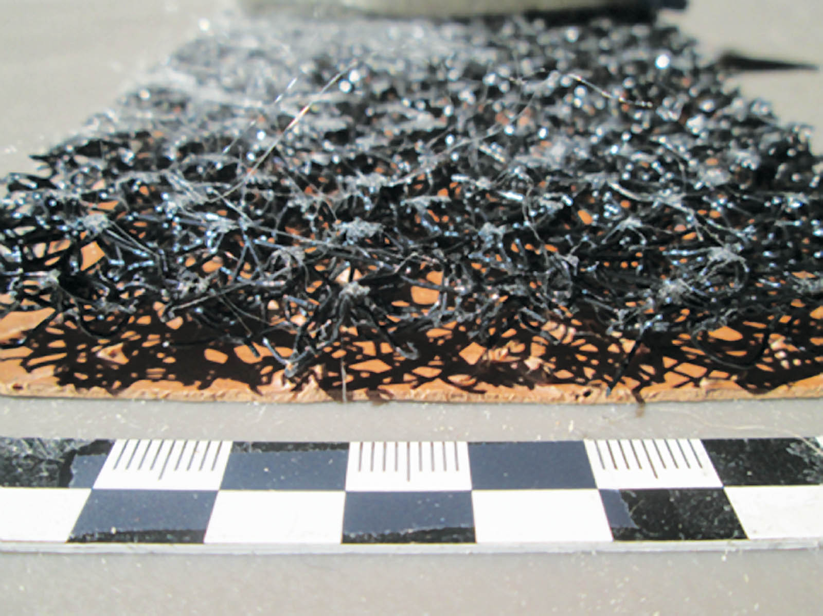
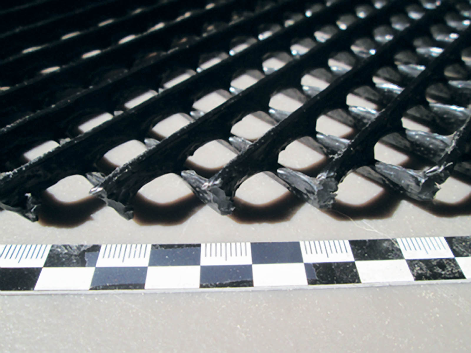
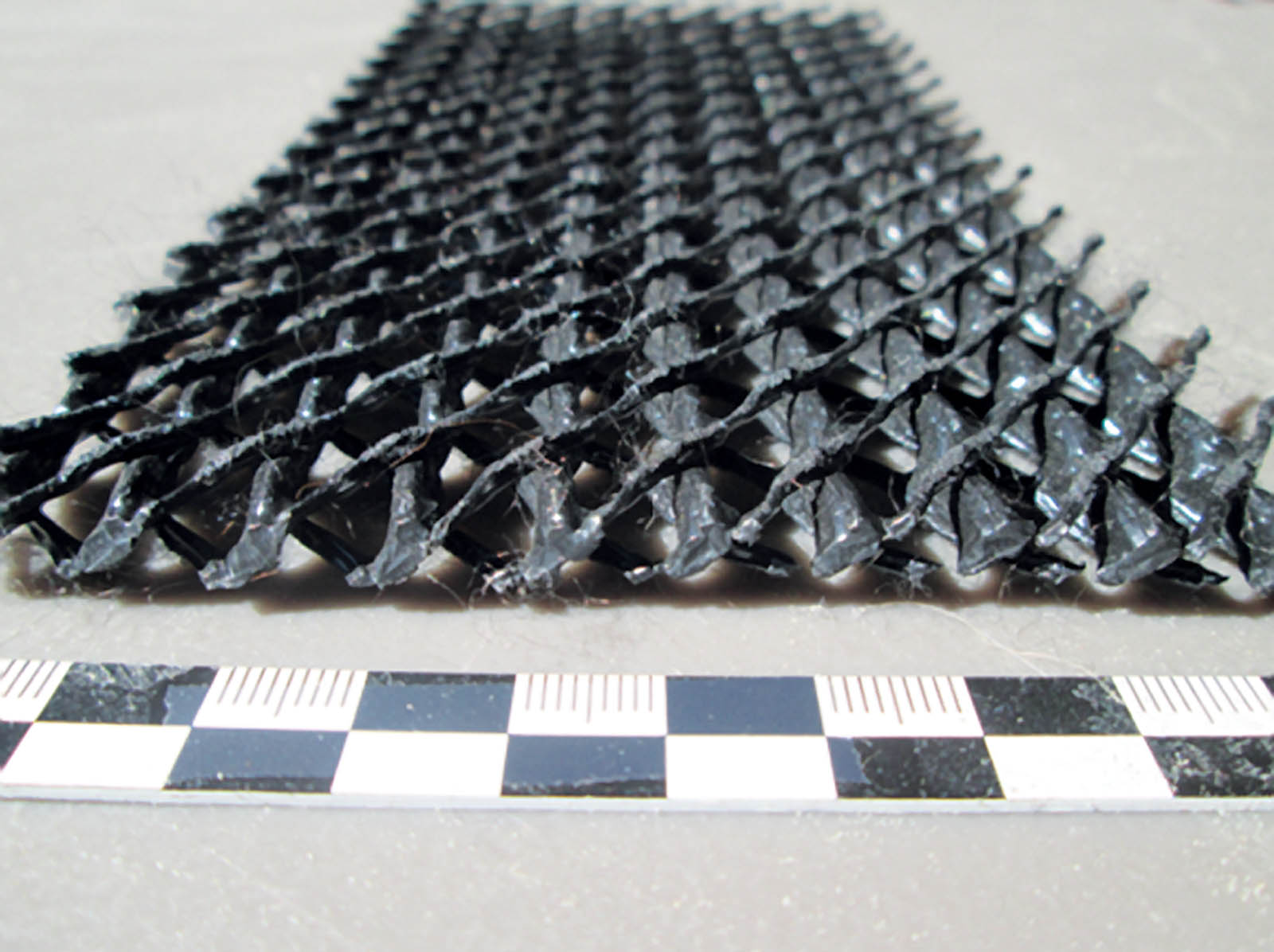
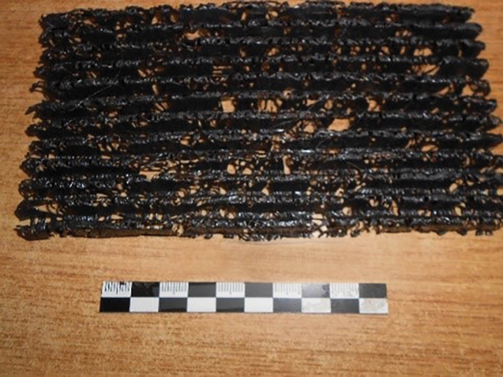
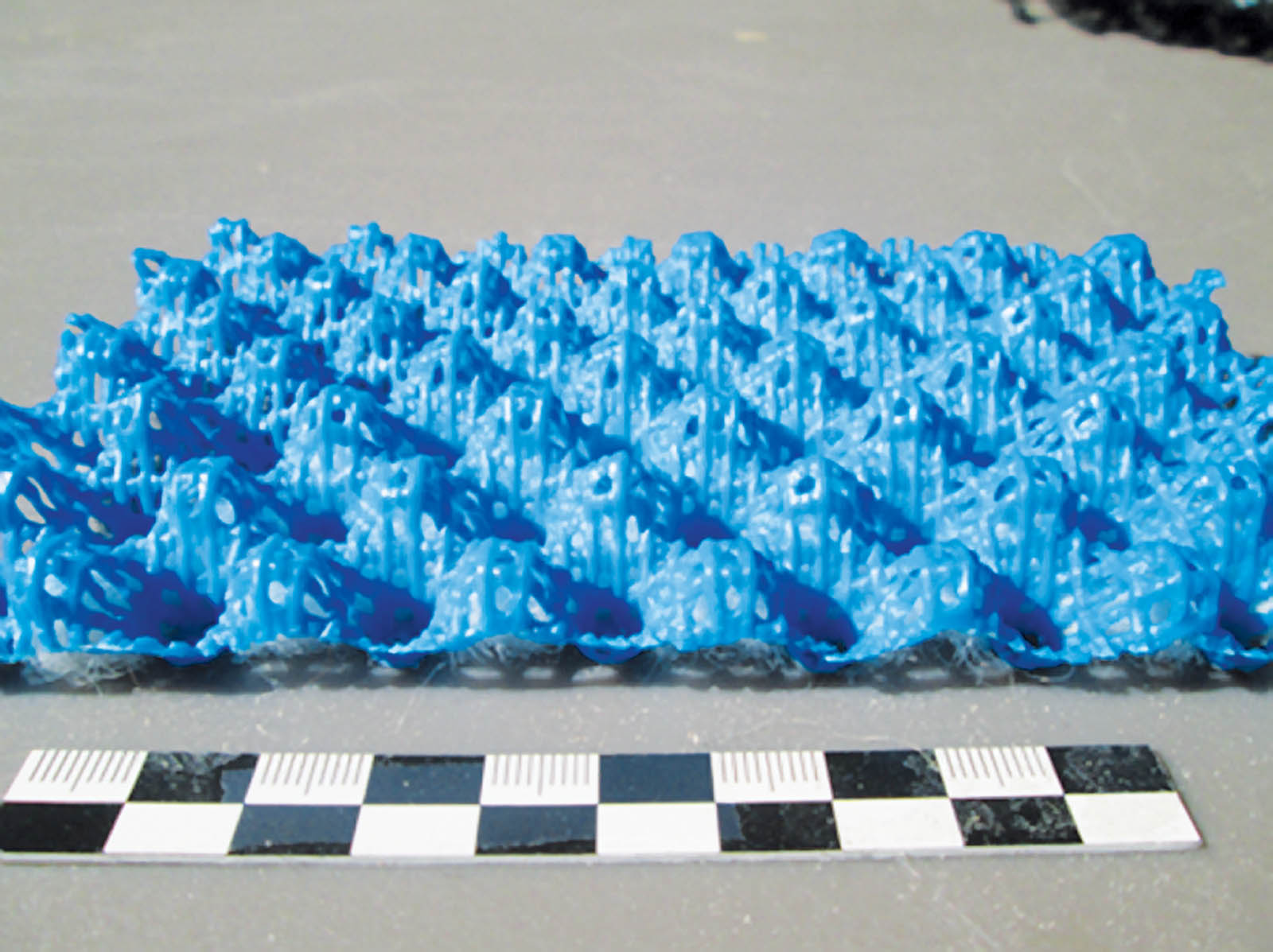
Location “1” is easy to accommodate using a geotextile filter since it is simply laid on top of the horizontal base (also called blanket) drain. Location “2” is more difficult construction-wise since each layer of soil between adjacent reinforcement layers must be wrapped accordingly. In so doing, it becomes a mini wraparound detail. In spite of the difficulty, it simply must be accommodated accordingly. Regarding location “3,” the geotextile filter must be on both sides of the back drain. This becomes a nightmare to construct using gravel as the back drain. It begs the question, “Why use gravel soil in this location to begin with?” The straightforward answer is to omit the gravel and use a geocomposite drain. In this regard, there are many drainage core types available under the two general categories of geonet composites and geospacer composites; see the photographs of Figures 2a–e. Let’s start using them on a regular basis and forget trying to stack a thin column of gravel vertically.
At this point in time we know that there are far too many MSE wall failures and that the majority are mobilized by water within or around the reinforced soil zone. By designing and placing geotextile filters, the high-permeability gravel of the front drain and base drain will be preserved. Even further, the use of geosynthetic drainage geocomposites for back drainage eliminates the contractor’s challenge of building a near vertical column of gravel. Furthermore, geosynthetic drainage composites automatically come with geotextile filters bonded onto both sides of the drainage core.
We feel that by not providing geotextile-protected drainage to the front, base and back drainage systems of MSE wall structures it will result in long-term failures, most likely in the lower regions of the wall where hydrostatic pressures are highest. Incidentally, the repair of such toe failures is incredibly difficult and expensive, and certainly looks bad for all parties involved and for the industry as a whole.