 TEXTILES.ORG


Recent project experience that included continuous peel testing across the roll width of geocomposite materials has shed light on the issue of peel strength between geotextiles and geonets that are heat-bonded together. The variability of peel strength across a roll width is found to be much greater than expected, with the typical standard deviation often greater than the nominal specified target value. Many more poorly laminated zones may exist across the roll width than the average designer might presume. The current number of specimens (five) taken to evaluate peel strength across a roll width, in accordance with ASTM D7005, is believed to be inadequate for evaluating material conformance with design specifications.
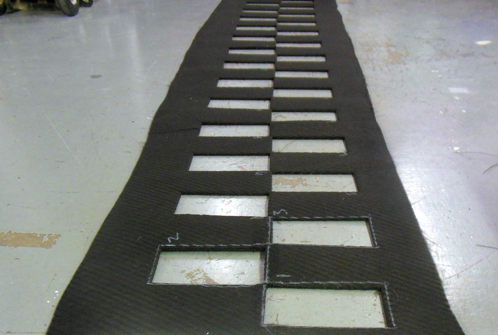
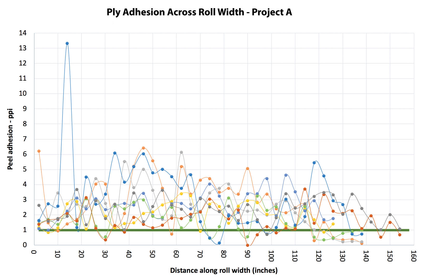
Figure 1b shows a sample where contiguous 4-inch (10-cm) wide specimens were cut in a checkerboard pattern across the roll width. Approximately 40 samples can be cut from a roll, depending on the roll dimensions and the width of the unbonded edge. Figure 1a presents an example of peel test results where each specimen test was conducted in accordance with ASTM D7005 and was plotted across the roll width. This plot could be called a “peel strength profile.” This particular sample yielded 38 specimens that resulted in an average peel strength of 1.65 pounds/inch (290 N/m) with a standard deviation (SD) of 1.32 pounds/inch (231 N/m), assuming that the results are distributed normally. It is noteworthy that even though the average value of 1.65 pounds/inch (290 N/m) is soundly above the target specification for this project of 1.0 pound/inch (175 N/m), 12 of the 38 specimens (32%) are below the target specification.
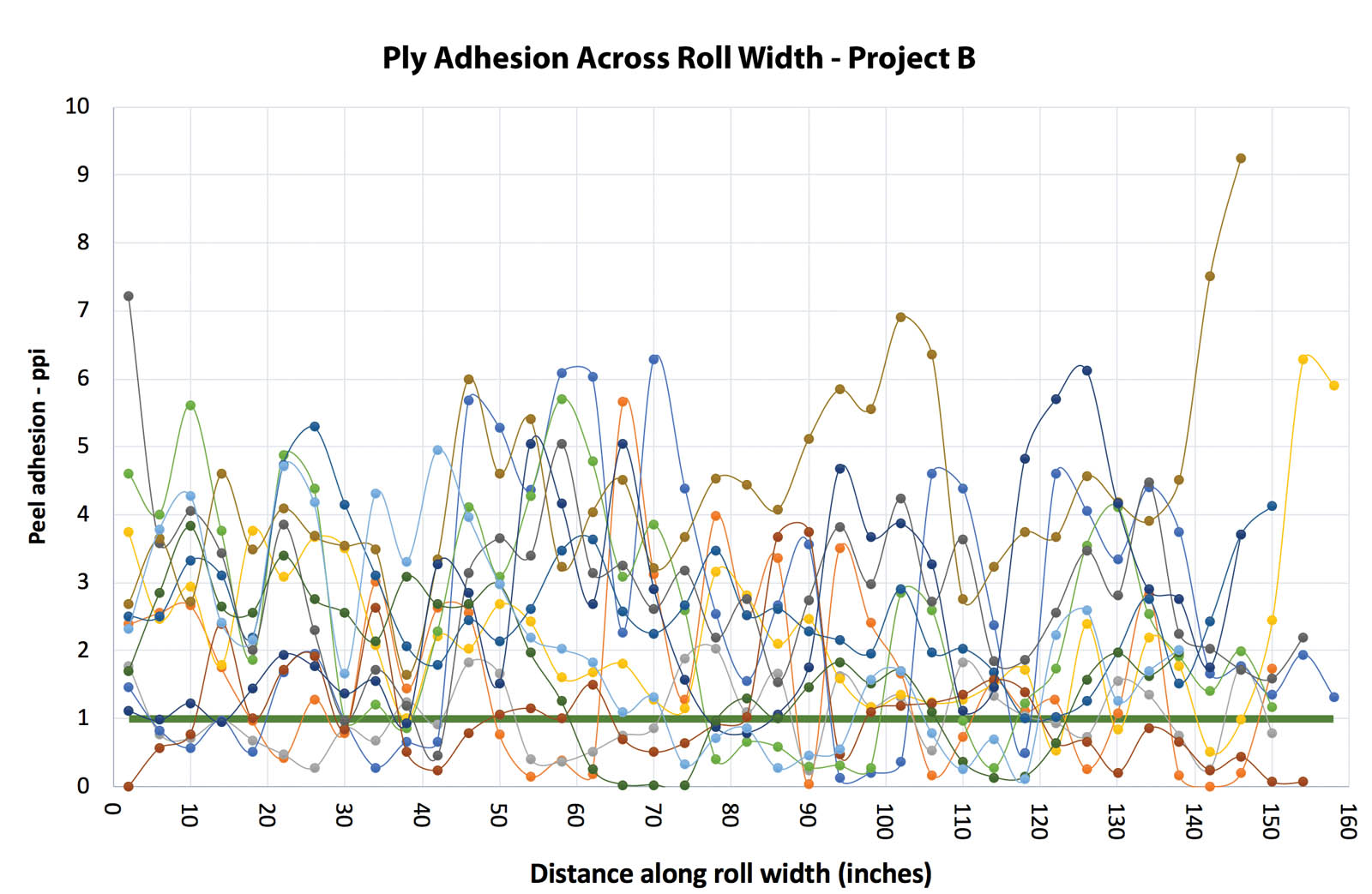
Figures 2 and 3 present peel strength profiles on samples from both sides of 10 different rolls on two separate projects. The thick, solid, horizontal line is the target specification on both projects of 1.0 pound/inch (175 N/m). It is interesting to note that the data sets from both projects coincidentally produced very similar statistics, with average peel strengths for all samples of 2.3 pounds/inch (403 N/m) and with SD of 1.25 pounds/inch (219 N/m), assuming the results are normally distributed. The question is, however, given the high variability, what are the appropriate acceptance criteria for the peel strength profile?
The reason this issue is important is related to shear strength and slope stability. The potential for delamination at the bonded interface is increased by hauling, dumping and spreading cover soil on top of the liner system. The postconstruction condition of this interface will affect the long-term reliability for slope stability.
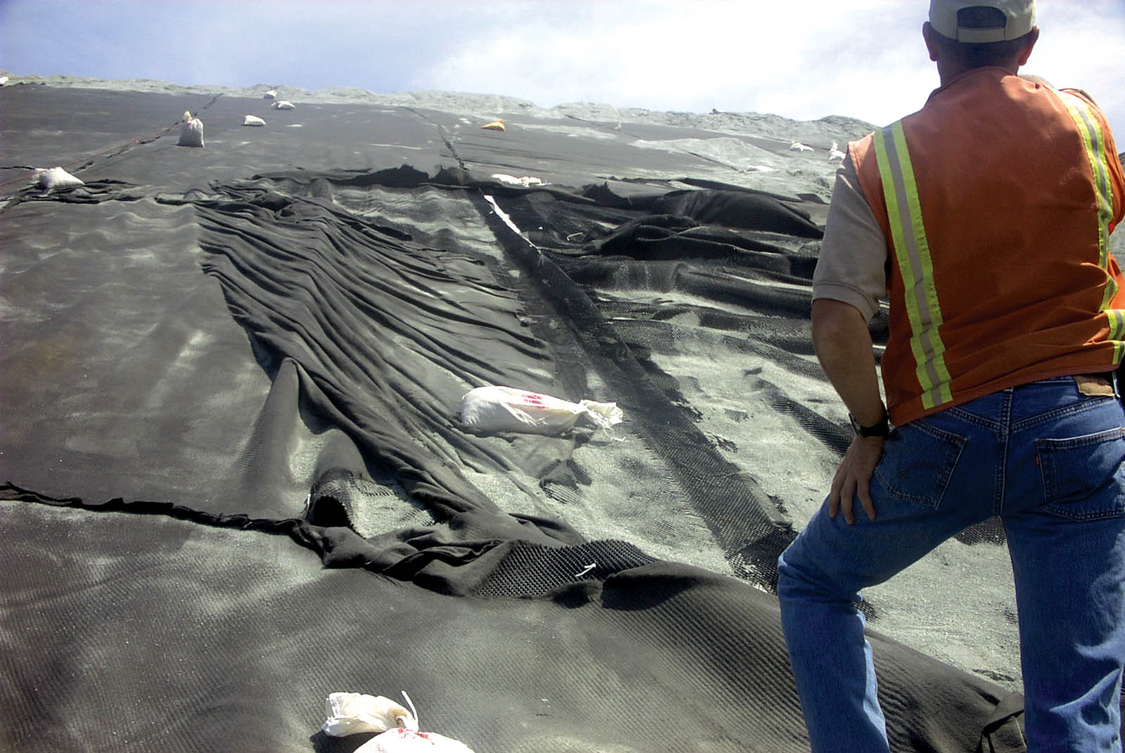
Thiel and Narejo (2005) described a case history of a geocomposite that had poor lamination strength, which resulted in slippage during construction (Figure 4 on page 40). That white paper attempted to correlate index peel strength with shear strength, and concluded that on projects where shear strength was critical, a minimum peel strength of 1.0 pound/inch (175 N/m) minimum average roll value (MARV) is recommended as an industry standard. Up until that time, the industry standard for lamination had been 0.5 pounds/inch (88 N/m). Note the calculation of MARV, according to the definition provided by ASTM D4439, is “the typical value minus two (2) standard deviations.”
Interestingly, the Thiel and Narejo (2005) paper also mentioned that the described problematic geocomposite had passing peel test results from both manufacturing quality control (MQC) and construction quality assurance (CQA) conformance testing, and none of the extremely poor lamination was picked up in the laboratory testing. While the article did not dwell on this point, there was a significant disconnect between the laboratory test results that indicated well-bonded material versus the reality of the field-deployed material that had numerous large “holidays.” The discrepancy was only fully appreciated after there was slippage during construction. A similar discrepancy between the results from the standard five-specimen protocol of ASTM D7005 testing, compared with results from a complete peel strength profile, was observed for the projects represented in Figures 2 and 3. The very high variability of the lamination process, which is the subject of this article, was not known by Thiel and Narejo (2005) at the time of that writing.
Based on these experiences, the author believes that the current industry approach for specifying and evaluating geocomposite peel strength is inadequate. More direct industry guidance needs to be provided to design practitioners, manufacturers, testing laboratories and CQA inspectors to provide a holistic approach for addressing this issue. This article is intended to re-invigorate the discussion that was started in 2005 by presenting additional data and findings. While some preliminary recommendations are presented herein, there remain significant opportunities for all the parties involved (manufacturers, designers, academics, technicians and installers) to weigh in on this issue.
Design practitioners: Specifications
The product lamination requirements need to be defined in the specifications. On projects where the long-term interface shear strength is important, the author recommends the following language be clearly stated in the specifications:
- The unbonded edge distance should be restricted. For critical projects, less is better, and a maximum average of 6 inches (15 cm) is recommended.
- The laminated area should be uniformly bonded with a minimum of weak spots, blisters or holidays.
- Thiel and Narejo (2005) suggested that a 1.0 pound/inch (175 N/m) target value might be considered appropriate as a starting point for a lamination peel strength on critical projects. Certainly, this is an issue ripe for additional research and is subject to engineering judgment considering aging and durability. On critical projects, the author is requiring a complete peel strength profile (contiguous specimens across the roll width) on selected CQA conformance samples. Using 1.0 pound/inch (175 N/m) peel strength as a goal, the author has recently considered two alternative specifications:
-
FIGURE 3 Peel strength profiles from both sides of six rolls on Project B Alternative 1 assumes that the peel strength results are normally distributed. Based on this assumption, the author has calculated that the peel strength results from specimens cut contiguously across the roll width should have an average value on the order of a minimum of either (a) [0.75 • SD + 1], or (b) 2.5 pounds/inch (438 N/m), whichever is less. The SD would be determined separately for each sample tested based on the 40-plus specimens from that sample. Note that this specification would result in a minimum required peel strength of 1.0 pound/inch (175 N/m) if the lamination was uniform with no variation.
- Alternative 2 makes no assumption regarding the mathematical distribution of the peel results, but considers only the required mobilization of shear strength in both the bonded and unbonded areas of the geonet/geotextile interface, and establishes a reliability criterion for maintaining a large portion of the area in a well-bonded condition after the debilitating construction forces have occurred. Based on this criterion, the author has derived the following specification whose derivation will be published in the upcoming proceedings for the Geosynthetics 2019 conference, occurring Feb. 10–13, 2019, in Houston, Texas:
- The geocomposite drainage layer material shall consist of nominal 14- to 15-foot [4.3–4.5-m] wide rolls of a geonet core having nonwoven needlepunched geotextiles heat-bonded to both sides, with a maximum of 6 [inches (15 cm)] of the geotextile unbonded along both sides of the geonet for purposes of seaming. The heat-bonded lamination between the geotextile and geonet shall have a uniform ply-adhesion (peel) strength over the remainder of the panel area, with a minimum of “blisters,” “holidays” or other weakly bonded areas. This specification requires a minimum 25-percentile threshold peel strength = 0.8 pound/inch [140 N/m] based on continuous-specimen profile testing across the roll width. The specimens shall be tested in accordance with ASTM D7005, with the test method modified to allow for continuous 4-inch [10-cm] wide specimens taken in a checkerboard pattern across the entire roll width. For example, if the initial roll width is 14.5 feet [4.4 m] and has 6[-inch] unbonded edges, then a minimum of 40 4-inch wide specimens should be taken across the width of the roll for one test. This specification requires that 30 of the 40 specimens would be required to have a peel strength greater than or equal to 0.8 ppi [140 N/m] for each side being tested.
- The author believes that both specification alternatives will produce acceptable material, but that Alternative 2 is more defendable and has a more straightforward pass/fail criterion. The author and Doug Gatrell, an engineer at GHD, verified that the peel strength data is lognormally distributed and not normally distributed. This makes sense for data that has low mean values and cannot have results less than zero. Assuming that the data is normally distributed, in this case, is nonconservative. However, the Alternative 1 specification was prepared to offset this nonconservative assumption and is overall believed to be more conservative than Alternative 2.
- The maximum size of the construction equipment allowed on the slope should be specified. The minimum allowable soil thickness being spread over the geocomposite should be 12 inches (30 cm), and it is recommended that the spreading equipment be no larger than a Caterpillar D6 with LGP tracks. Smaller equipment will produce less potential for delamination and should be considered for slopes steeper than 33% (3H:1V). For larger soil-hauling equipment, greater soil cover thickness is beneficial because it will spread out the equipment loads farther.
- Materials should be pushed up from the bottom of the slope; pushing from the top down is discouraged except under special circumstances approved by the engineer and where field tests are performed.
Manufacturers: Lamination process and MQC
Manufacturing is an art, and the manufacturers of geosynthetics deserve a lot of credit for developing the vast array of products currently available. Even so, it is incumbent on them to develop manufacturing techniques and MQC programs that will meet the reliability expectations of the end user.
Manufacturers and experienced design practitioners understand that the transmissivity and shear-adhesion performance of geocomposites are inversely affected by the lamination process. Low temperatures and pressures will maintain maximum transmissivity but could result in weak lamination strength. Higher temperatures and pressures will increase lamination strength, but will also reduce transmissivity and could lead to damage of the geotextile or geonet core if excessive. Thicker geonet cores can be used to regain transmissivity lost by a more aggressive lamination process, but at a cost.
The cleaning of the heater bars, amount and distribution of heat, temperature of surroundings, air circulation, and roller pressure can affect the quality and uniformity of bonding between the geotextile and the geonet. These, and other things, are parameters that are in the realm of proprietary manufacturing and are outside the realm of specifiers.
Manufacturers should try to detect poorly laminated zones during the manufacturing process and remove that material from the shipment. The first opportunity to identify weakly laminated or delaminated material is during the manufacturing process by workers or samplers on the manufacturing line. Perhaps a simple handheld dull blade or other appropriate tool could periodically be run along the entire cut edge of the end of a laminated roll to manually detect weakly laminated material. Based on field experience, the author believes that a trained person can quickly become “calibrated” to detect significant noncompliances using this technique.
The second opportunity to identify weakly laminated material would be during the MQC sampling and peel testing procedure. For both MQC and CQA conformance testing, the author recommends a baseline testing frequency, using complete peel testing, on an initial basis of once per 50,000 square feet (4,645 m2). Ultimately, manufacturers will need to perform suitable testing so that they understand their own product variability adequately to confidently bid projects.
Testing laboratories: Test method
ASTM D7005, “Standard Test Method for Determining the Bond Strength (Ply Adhesion) of Geocomposites,” promulgated in 2003, is the current industry standard. The method prescribes cutting out five 4-inch (10-cm) wide specimens distributed evenly across the roll width, measuring the peel strength in accordance with the procedures described in the test method and reporting the peel strength results for each specimen, the average of all five and the standard deviation.
The current ASTM D7005 test method requires only five specimens across the roll width and measures the peel strength for 13% of the bonded area across a standard roll width. The author believes that this is inadequate for detecting noncomplying areas.
The author is recommending that the ASTM standard be revised, but that will likely take a few years to accomplish. In the meantime, the author recommends that specifiers of MQC/CQA testing require the ASTM D7005 testing protocol be modified for their individual projects as follows:
- Samples cut for MQC and CQA testing shall always be the entire roll width, typically by 3-feet (0.9-m) long in the machine direction.
The width of the unbonded zone on the edges of the rolls needs to be measured and reported. - For the bonded zone, 4-inch (10-cm) wide specimens should be taken contiguously across the roll width. To avoid specimen-cutting interference, the specimen locations can be on a checkerboard pattern, as shown in Figure 1b on page 38. For a typical manufactured roll, this would result in about 40 specimens across the width of the roll.
- All specimens should be tested in accordance with the ASTM D7005 test method, and the results reported for each specimen, the 25th percentile, the average and the standard deviation (assuming data is normally distributed, even if it is not actually so).
- If a reduced number of specimens across the roll width are allowed for some of the samples (which the author does not recommend), then the testing technician shall divide the roll width into equal sections for obtaining the required number of specimens. Within each particular section, the locations for cutting the specimens shall be biased toward areas that exhibit weaker peel and, especially, to cut specimens from those areas that may exhibit low or zero peel strength. While the technician is not expected to conduct an exhaustive evaluation to find the weakest areas, the specimen locations should never intentionally be biased toward areas that exhibit stronger peel.
The time and cost of a continuous-specimen test protocol is not overbearing. The same sample size (typically 3 feet [0.9 m] by roll width) gets sent to the laboratory regardless. Whereas the typical five-specimen test cost might be on the order of $40, the continuous-specimen test might be on the order of $285 (based on a project quote in April 2018). Yes, it is about seven times more, but considering the limited number of conformance samples on a project and the relative importance, it is a minor CQA cost.
CQA: Field inspection
The last opportunity to identify weakness in the geocomposite bonding is during field deployment. At this time, field inspectors need to observe the following:
- Obvious signs of nonlaminated areas in the form of blisters should be watched for as the material is being deployed. If blisters are observed, more detailed inspection of those areas should be performed by pushing on the material with the soles of boots, particularly to investigate if there is a tendency for a machine-direction defect. The size of any blisters needs to be recorded and reported to the engineer.
- The ends of panels (at least every fifth panel) must be periodically tested by the field inspector by hand pulling the geotextile away from the geonet (on both sides of a double-sided product). Weak areas, which generally run in the machine direction, are readily identified in this way and, if discovered, must be reported to the engineer and be more thoroughly evaluated through additional sampling and laboratory testing.
- If panels are found to contain weakly bonded areas in excess of what is deemed acceptable by the engineer, those panels must be removed and a more detailed investigatory program undertaken that searches for the extent of the problem. It is also important to involve the manufacturer to try to understand the reason for the problem, which will be helpful in determining how much of the shipment might need to be rejected.
The main culprit that causes damage at the bonded interface is the operational technique of the construction equipment that is hauling, dumping and spreading cover soil on top of the liner system elements. Appropriate and diligent CQA monitoring of this process is important.
Conclusions
Because of the high variability inherent in laminating geotextiles to geonets, the current sampling and testing protocol as embodied in ASTM D7005 is inadequate to characterize the peel strength of geotextiles that are heat-bonded to geonets. If each party takes its available opportunities to detect geocomposite bonding deficiencies, a much higher degree of reliability for compliant material will likely be realized. The process begins with a clear specification outlining the project expectations, followed by diligent MQC, improved laboratory testing methods and focused field inspection techniques.
Richard Thiel, P.E., is the president of Thiel Engineering in Oregon House, Calif.
References
Thiel, R., and Narejo, D. (2005). “Lamination strength requirements for geonet drainage geocomposites.” Proc., 18th Annual GRI Conf./ASCE GeoFrontiers Conf., ASCE, Reston, Va.