 TEXTILES.ORG

Over the years, there have been many discussions raising concerns about having geomembrane field seams located horizontally on side slopes. By not allowing such seams, it usually results in many short roll lengths that become either unused or difficult to tailor into the flat area of the project. Stated differently, the installation costs increase accordingly. It appears that the concerns over such nonuse is a lack of seam strength along the side slope. While geomembrane seams in a shear mode typically approach the full strength of unseamed sheet geomembranes, it is the peel strength that is often questioned. For example, in most specifications (including the Geosynthetic Research Institute’s GRI-GM19a for the polyolefin geomembrane types of high-density polyethylene [HDPE], linear low-density polyethylene [LLDPE] and flexible polypropylene [fPP]), the shear strength is 95% of the unseamed sheet tensile strength, while the peel strength is 62% of the unseamed sheet tensile strength. This significantly lower peel value appears to be the central issue when considering side-slope geomembrane seaming.

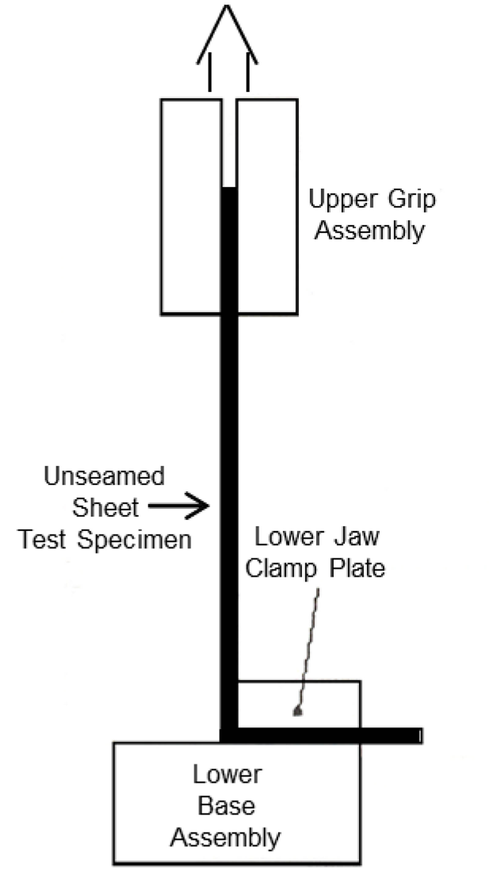
As will be shown, the lower peel strength percentage is an artifact of the manner of laboratory testing of the unseamed sheet strength that is used for comparison purposes. This is because the peel strength test (necessarily in a 90° configuration) is often compared to the unseamed sheet strength in its traditional linear configuration (i.e., the specimen tensile forces align with the upper and lower testing grips). As shown by Fred Struve and George Koerner in 2005, however, when the unseamed sheet tensile strength is measured in a 90° configuration (see Figure 1a and 1b), the peel strength percentage is much higher than when the sheet is tested in its linear configuration.
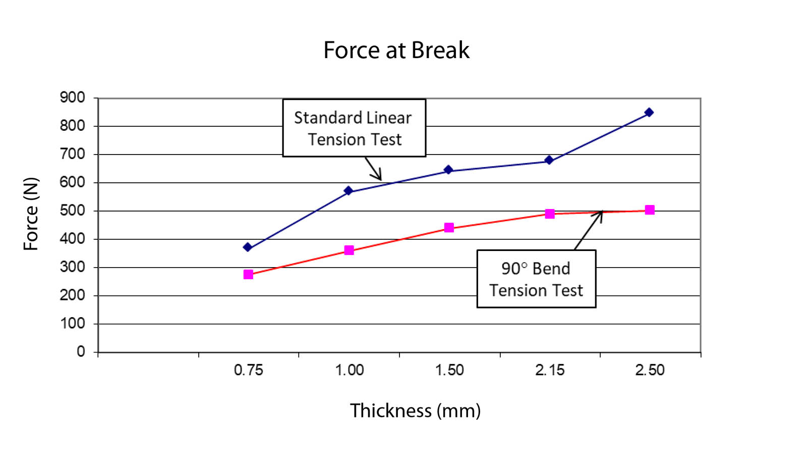
Figure 2 shows the differences in unseamed sheet strength in both modes of tension testing for HDPE geomembranes of various thicknesses. Readily seen is that the 90° tension test results described herein are always less than the standard linear tension test results. The decreases with increasing thickness are 24%, 37%, 31%, 30% and 41%, respectively. Averaging these values gives 33%. This represents the average amount that unseamed sheet strength is lower in a 90° alignment than when the standard linear test is used. In comparing such lower sheet strength values to the actual seamed peel strength (which was hypothetically 62% of the linear configuration), the implication is that the percentage of peel strength now becomes 62% of the 90° unseamed sheet strength. Thus, 62% of (100 – 33) becomes 62/67 = 93% of the 90° sheet strength. As such, this percentage is quite comparable to the seam shear percentage of 95%, as mentioned earlier.
Based on this, there are three aspects of field geomembrane deployment that should be considered to alleviate any remaining concerns over horizontal seams on side slopes. They are the following:
- When a geomembrane is placed on a slope to be seamed to a continuation of one in a horizontal manner, the upper geomembrane must be shingled over the lower geomembrane. This will ensure that the shear seam strength is being mobilized if tensile stresses arise in the sheets. In this regard, we believe that it is less likely for the seam to be challenged in a peel mode.
- Horizontal seams should be staggered with respect to adjacent seamed sheets such that the seams do not communicate with one another in a straight line along the slope.
- If the entire geomembrane sheet on the side slope does go into tension (e.g., due to inadequate frictional strength with the underlying soil or other geosynthetic), the tensile stress is minimum at the bottom of the slope and maximum at the top. This infers that horizontal seams should be located as low as possible on the slope. We believe that the longest possible sheets should be placed from the anchor trench at the top of the slope and come downslope as far as possible to be continued with shorter sheets, rather than short “filler” sheets located near the top of the slope.
The intransigence toward using horizontal field seams of geomembranes is largely unfounded. Furthermore, to have regulations promulgated against such seam orientation under any, and all, circumstances is far too restrictive, and the design engineer should be allowed to assess the situation on a site-specific basis.
Reference
Struve, F., and Koerner, G. R. (2008). “Behavior of HDPE geomembrane sheet and seams subjected to a 90° tensile test,” Geosynthetic Research and Development in Progress: Proc., Geo-Frontiers 2005. R. M. Koerner, G. R. Koerner, Y. G. Hsuan and M. V. Ashley, eds., ASCE, Reston, Va.