 TEXTILES.ORG

Geotextiles play an essential role in geotechnical projects. A significant use for geotextiles is as a separator and filter in drainage and erosion control applications (Holtz 2002). A temporary erosion control application geotextile, such as silt fencing, is used to prevent soil erosion by containing the soil and turbid water in a onetime operation. For a permanent erosion control application, however, a geotextile must be designed for long-term use. While most applications of geotextiles are successful, there are some case histories where geotextiles had inadequate performance. Koerner and Koerner (2015) reviewed 69 cases of geotextile failures where the term “failure” was used to describe the unsatisfactory performance of the geotextile filter or the associated drainage system.
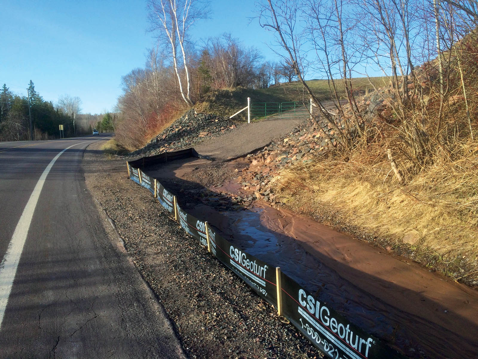
This article discusses the construction of a road through a glacial soil slope to access Michigan Highway M-203 near Hancock on the Keweenaw Peninsula in the state’s Upper Peninsula (UP), as shown in Figure 1. While most local cut slopes are seeded or mulched after construction, in this case, due to the slope’s location next to a state highway, the contractor used riprap with a geotextile separator to protect against erosion. The slope, however, failed dramatically in the spring following construction the previous summer. This article focuses on determining the likely cause of the slope failure.
Review of local slope construction with failures
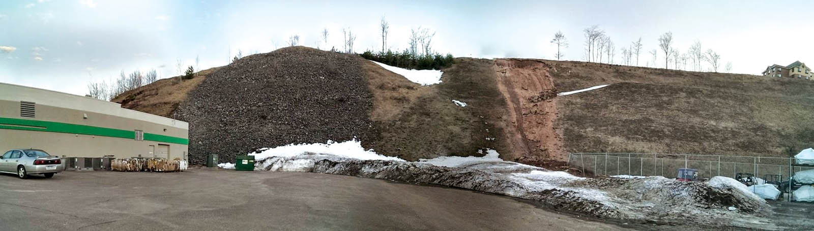
In the UP, it is common to have limited landslides develop on newly constructed slopes the spring after construction due to a combination of ground freezing and heavy snowfall. Figure 2 shows a commercial site where the slopes were excavated to an average of 35°, with some portions as steep as 40°. The slope remained stable for 30 years when a section of the slope failed after a record cold winter. Riprap was placed on the slope, and it has remained stable. Some years after this failure, however, another winter with relatively high snowfall and record low temperatures caused the slopes on either side of the riprapped section to fail. These failures were not remediated but have remained relatively stable.
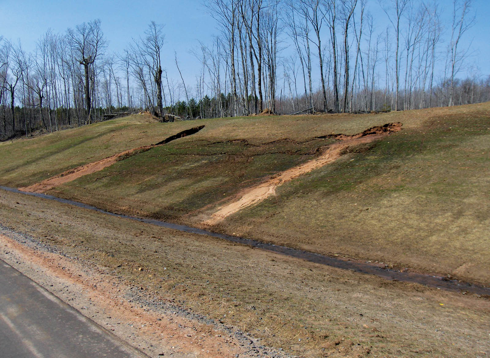
Construction on slopes as steep as 35° to 40° is difficult. Most steep slopes are constructed using bulldozers and, depending on the type and make of the bulldozer, slopes are generally not constructed steeper than 40°. On steep slope construction, the method is to push the soil downslope. One problem with this method in glacial soils, however, is that it is common to encounter layers of silt or clay in the soils. As the bulldozer pushes past these layers, the soils are spread along the slope, creating lower permeability zones on the slope’s surface. Further, in the spring, snowmelt and rainwater draining through the soils encounter the low-permeability layers (typically horizontal silt and clay layers) in which the water ponds on these layers forcing liquid to move laterally to the slope. However, the water encounters the low-permeability surface layers along the slope, thus developing pore pressure behind the slope resulting in slope failures, as seen for both a new slope (Figure 3a) and an older slope (Figure 3b).
Based on numerous observations, it appears that after vegetation has established on the slope or riprap placed on the slope, the slopes tend to be stable over time with the exception of in the case of extreme winter conditions, after which spring landslides become more common. Furthermore, when landslides do occur, riprap tends to be effective in remediating the slope, even on steep slopes. Geotextiles are generally not used on slopes in this area.
M-203 slope failure
The failed Highway M-203 slope is near Lake Superior and receives significant lake-effect snow, averaging 16 feet (5 m) per year. Temperatures in the summer average 75°F (23.9 C°) and in the winter 9°F (-12.8°C) (U.S. Climate Data 2016). The area averages five months of below-freezing weather between November and March.
The road was constructed through a 30-foot (9-m) high glacial soil slope to access M-203. The slope was excavated to a 27° slope. Although 27° slopes are considered stable, a woven geotextile layer was placed on the slope to protect against erosion and then riprap was placed on top of the geotextile to protect against potential spring failure. In spring 2014, however, the north-facing slope failed catastrophically, causing a significant amount of sand to flow onto M-203 to a depth of 2 feet (0.6 m) and forming a sinkhole behind the slope. Crews removed the sand from the highway to allow traffic to pass. Later that summer, the slope was reconstructed with a new ditch; a woven slit-film geotextile, similar to a silt fence, for separation; and riprap.
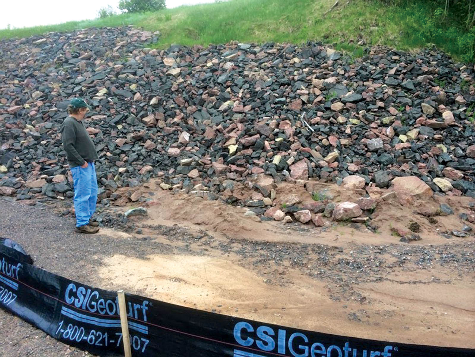
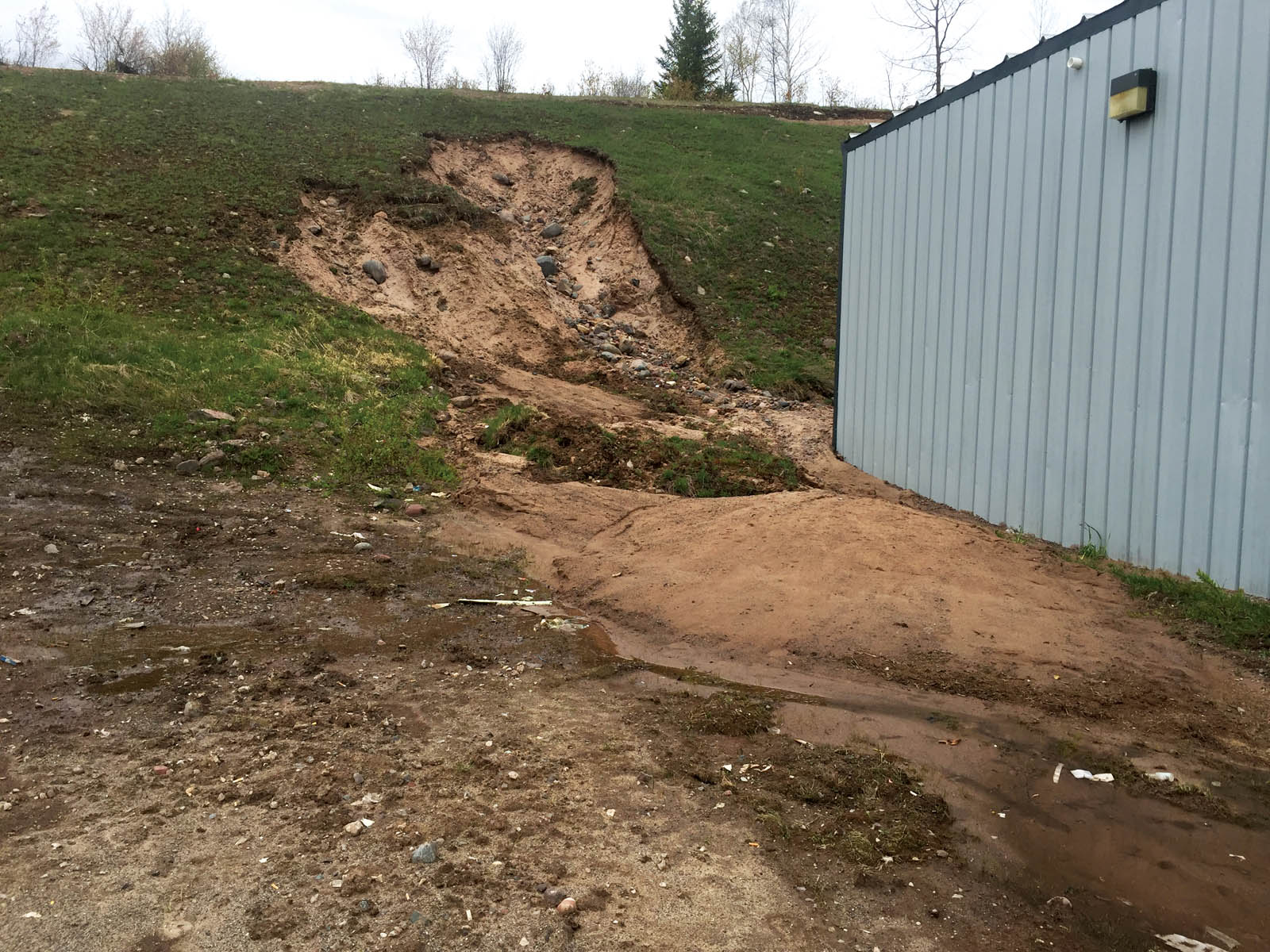
Unfortunately, no photographs of the failure were available. The spring after remediation, however, a smaller failure again occurred on the slope, with sand and water flowing out, as shown in Figure 4. The site was cleaned up and minor modifications were made to the slope.
Site geology and soils
The slope soils consist primarily of stratified light brown glaciolacustrine sand and silt, classified as an SM soil with fines averaging 8 to 15% per ASTM D1140-14 (ASTM 2014), along with limited gravel and cobbles. Figure 5 shows the mechanical grain size analysis for three soil samples taken from the excavated soil (Soil 2 to Soil 4). Due to a considerable amount of fines in the soil, the fines content shown in the figure is lower than the washed fines analysis indicated previously. The average coefficient of uniformity (Cu) = 10 and coefficient of curvature (Cc) = 3.3 for the four samples tested, based on a dry sieve analysis.
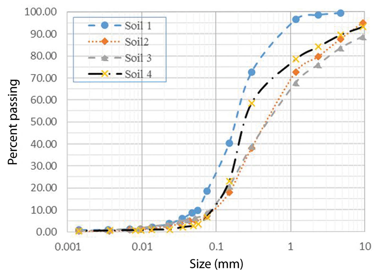
According to Luettich et al. (1992), soils with a Cc greater than 3 or less than 1 have a higher probability of internal instability. Kenney and Lau (1985) also note that internal instability is likely to occur in soils that have gently inclined sections (wide range of particle sizes) in the lower section of their grading curves. As such, a soil’s grain size analysis would suggest that the slope’s soil has a high probability of internal instability. Direct shear tests on the slope’s soil resulted in an average friction angle of 41°. This is consistent for sands from local sand and gravel quarries.
Erosion control geotextile
The geotextile used on the slope was a woven slit-film geotextile. The primary goal of the geotextile was as a separator between the soil and the riprap to control erosion below the riprap, since the slope was adjacent to a state highway. Given the area’s high snowfall and spring runoff, however, the geotextile must also function as a filter allowing water to pass through the geotextile and retaining soil particles beyond the establishment of vegetation, which will eventually develop in the riprap. Consequently, the geotextile used on the M-203 slope should also have been selected based on long-term filtration. In cases of poor filtration of the geotextile, groundwater cannot escape through the geotextile. This results in pore water pressure buildup behind the geotextile called ballooning.
Simplified filtration and clogging tests
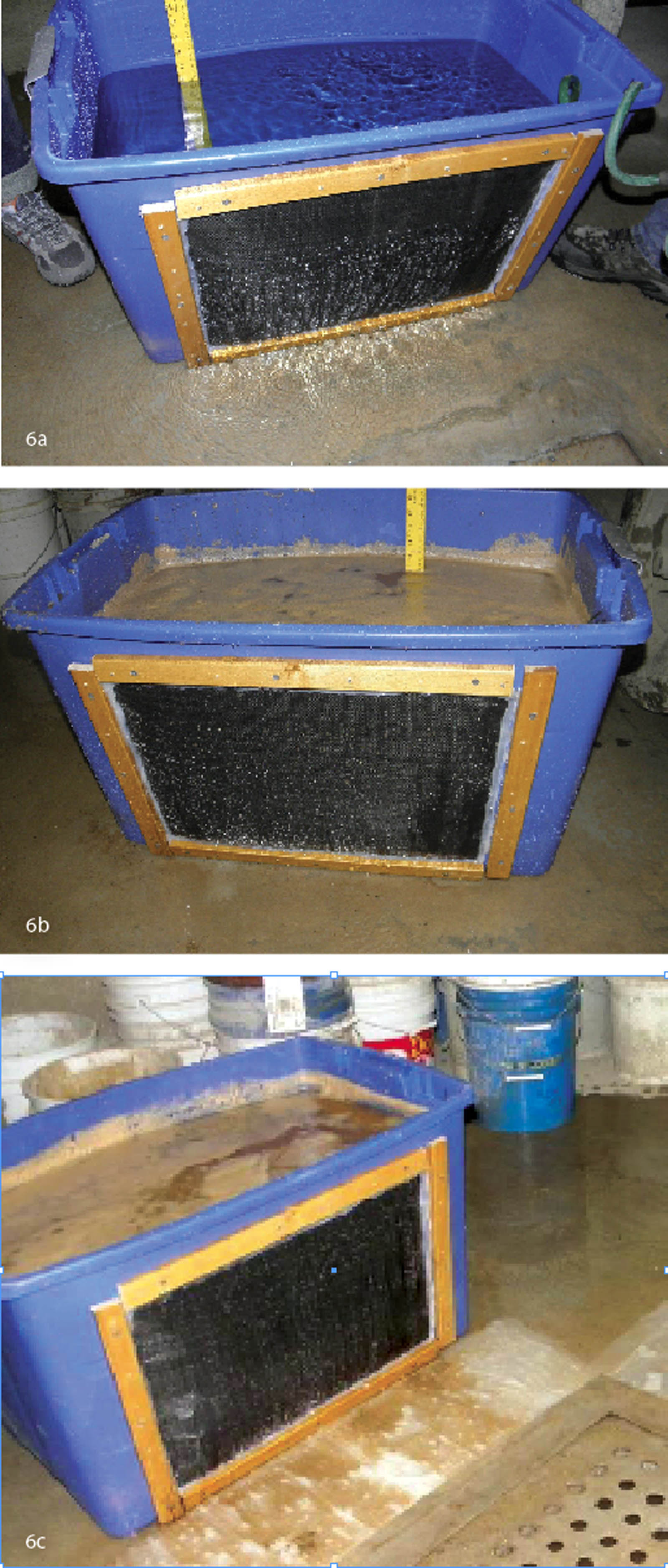
In a previous research project, the authors conducted a simplified filtration and clogging test on a standard silt fence product. The geotextile used on the slope was a woven monofilament fabric similar to fabrics used for silt fence control. To test the silt fence filtration and clogging capacity, one side of a plastic container was cut out and a geotextile fabric placed and secured in the opening. The container was filled with water to observe the water flow without soil, as shown in Figure 6a. After observing good water flow through the fabric, the container was emptied and then was refilled with a soil-and-water slurry. During the test, water was added to the container to maintain a constant slurry height. The silt fence performed well, retaining the sediment and allowing water to flow through the silt fence, as shown in Figure 6b. After completing the test, the container was emptied, and the fabric was lightly washed with water. The test was then repeated, filling the bucket with a sand/water slurry. On the second filling, however, the fabric failed to function properly, allowing only a limited amount of water and sediment to filtrate through the fabric, as shown in Figure 6c. Eventually, the silt fence pores clogged, significantly reducing the water flow. The test was repeated a number of times. In all cases, the fabric failed to function well after the first sand/water slurry was placed in the bucket. Inspecting the fabric, it was seen that many of the available openings were clogged with sediment.
Discussion and conclusion
Slopes constructed in the area range from 27° to 40°. Due to the soil’s high friction strength, these slopes tend to be stable over time, with the exception of limited slope failures in the spring after initial construction or after an extreme winter with either higher-than-usual snowfall or deep freezing. In general, flatter slopes (27° or less) are considered safe, and riprap is not utilized. In this article, however, the slope was adjacent to a state highway, and the contractor used both riprap and a geotextile separator to protect the slope from both potential erosion and failure. In cases where a contractor decides to use a geotextile fabric, it is a common for the contractor to use a lightweight and relatively inexpensive geotextile. While the issue of separation is clearly understood, the issue of filtration tends to be overlooked. It was, therefore, a surprise to the contractor (and site owner) the following spring when the dramatic slope failure occurred. The apparent cause of the failure was a buildup of pore water pressure behind the geotextile, which most likely became clogged the previous fall, winter and early spring.
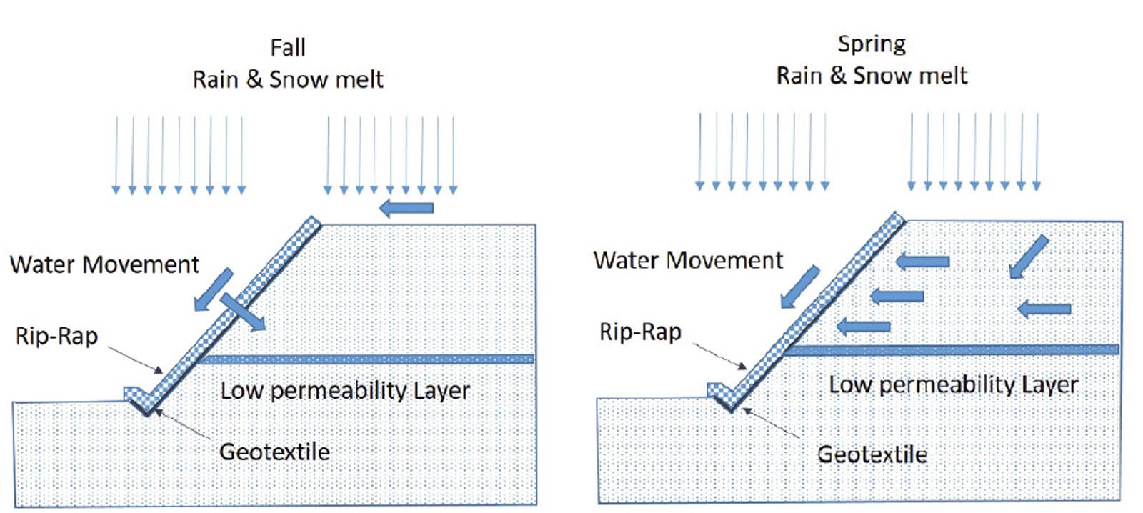
The slope was constructed in the summer. Since the groundwater table was below the slope, it did not contribute water flow into the slope at the time of construction. In the remaining summer and fall, however, rain and early snowmelt would have flowed over the surface of the geotextile, carrying some amount of sediment, as illustrated in Figure 7. It is believed that at this point the geotextile became clogged but probably not completely as to prevent water from flowing through the geotextile. In the spring, however, the snowmelt would have contributed significantly to groundwater flow. Further, the slope was constructed at the base of a farm field. Beyond the farm field was a 300-foot (91-m) high slope providing significant groundwater to the area, especially in the spring. Seeps are common along this section of highway, suggesting the presence of localized silt or clay layers in the soil.
These layers in turn would pond the groundwater, causing the water to flow laterally toward the slope. As discussed above, the soils are likely internally unstable, which is typical of glacial soils and would have caused particle migration into the geotextile, resulting in additional clogging. Once the geotextile was clogged or mostly clogged, pore water pressure developed behind the geotextile. The weight of the riprap in turn would have allowed additional pore water pressure. At some point, the pore water pressure excessed the ability of the riprap to maintain the slope’s stability resulting in the dramatic slope failure and soil liquefaction flow the following spring. If the geotextile had been designed for filtration, however, it should have allowed water to flow through the geotextile, preventing slope failure. Moreover, if the slope had been merely lined with riprap, it is likely that water flow from the spring meltwater would have been able to exit the slope without building pore water pressure in the slope. In effect, it is believed that the geotextile, once clogged, acted as a barrier to the spring groundwater flow leading to the failure.
References
ASTM (2014). “Standard test methods for determining the amount of material finer than 75-μm (No. 200) sieve in soils by washing.” D1140-14, ASTM International, West Conshohocken, PA.
Holtz, R. (2002). “Geosynthetics.” In Civil engineering handbook, ed. W. F. Chen and J. Y. Richard Liew, CRC Press, Boca Raton, FL.
Kenney, T., and Lau, D. (1985). “Internal stability of granular filters.” Canadian geotechnical journal, 22(2), 215–225.
Koerner, R., and Koerner, G. (2015). “Lessons learned from geotextile filter failures under challenging field conditions.” Geotext. Geomembr., 43(3), 272–281.
Luettich, S., Giroud, J., and Bachus, R. (1992). “Geotextile filter design guide.” Geotext. Geomembr., 11(4-6), 355–370.
U.S. Department of Agriculture, Natural Resources Conservation Service. (2016). “Landforms of the Upper Peninsula, Michigan.” http://www.nrcs.usda.gov/Internet/FSE_DOCUMENTS/nrcs141p2_024355.pdf (July 4, 2016).
U.S. Climate Data. (2016). http://www.usclimatedata.com/climate/hancock/michigan/united-states/usmi1400. (July 11, 2016).
Amaneh E. Kenarsari, Ph.D., is a geotechnical staff project manager at ECS Midwest in Chicago, Illinois.
Stanley J. Vitton, Ph.D., P.E., is a professor in the Department of Civil and Environmental Engineering at Michigan Technological University in Houghton.