 TEXTILES.ORG

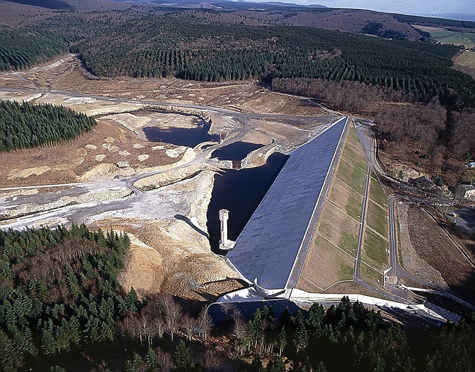

La Galaube Dam, an International Commission on Large Dams (ICOLD) facility in the south of France, completes the hydraulic system of the Montagne Noire area and provides a total water storage capacity in excess of 283 million cubic feet (8 million m3). To supply potable water to three counties and 185 municipalities in the region, the dam regulates the flow of the Canal du Midi, which is a United Nations Educational, Scientific and Cultural Organization (UNESCO) World Heritage Site. The dam-regulated water flows into the canal, producing electricity for Électricité de France S.A., a French electric utility company, and supplies water for irrigation. The lake created by La Galaube Dam covers an area of 168 acres (68 ha) at an altitude above 2,300 feet (700 m) (see Figures 1a and 1b).
The $20 million La Galaube Dam project, completed in 2000, involved the construction of the upstream waterproofing face of the dam.
Preparing the site
Two consulting engineering firms carried out design and supervision of works for La Galaube Dam project. They selected a design using an upstream geomembrane for waterproofing on a rock-fill embankment, because it was the most economical and had the least environmental impact. Construction used the mica schist excavated on the site to build the embankment, and minimal material needed to be imported. By contrast, some of the other options considered for the embankment—such as roller-compacted concrete (RCC) or zoned embankment with cores and shells—would have required large amounts of imported materials and truck traffic in a pristine area.

La Galaube Dam is a gravity embankment dam, and its stability is ensured by the weight of the rocks, which consist of about 28 million square feet (800,000 m3) of mica schist. The embankment rests upstream on a reinforced concrete plinth, founded on fresh or slightly weathered granite. La Galaube Dam is 1,250 feet (380 m) long at the crest, with slopes inclined at 2H:1V. The maximum height above the foundations is 140 feet (43 m). See Figure 2 on p. 28, which shows a cross section of the dam.
In addition, the project includes:
- A side spillway able to sustain a flow of 2,825 cubic feet/second (80 m3/sec)
- An upstream intake tower
- An underembankment tunnel, including a hydraulic tunnel and a monitoring tunnel
- A downstream outlet structure
Waterproofing of La Galaube Dam included lining the upstream face and grouting the foundation. The lining system installed on the upstream consists of:
- A 4-inch (10-cm) layer of unbounded material, with a 0–0.8 inch (0–20 mm) grading natural material, impregnated with bitumen emulsion
- A 4-inch (10-cm) layer of cold asphalt mix, with a 0–0.4 inch (0–10 mm) grading natural material
- A 189-mil (4.8-mm) bituminous geomembrane
- A 4-inch (10-cm) layer of fibrous concrete laid over a geotextile
The upstream slope was compacted with two 4-ton (3.6-tonne) static rollers. Those compactors were pulled from the dam crest by two hydraulic excavators equipped with winches.
A layer of unbounded material consisting of crushed limestone of 0–0.8 inch (0–20 mm) grain size was laid down as the subgrade. The minimum thickness of this layer was 8 inches (20 cm). Applied directly on the rock fill, it filled up the voids in the coarse rock and provided for a smooth working surface with minimal protrusions. Trucks imported a total of 5,000 tons (4,500 tonnes) of crushed limestone from a nearby quarry.
The material was moisture conditioned, transported with a rear dump truck and unloaded at the crest along the slope while graded to the desired thickness using bulldozers. The bulldozers were equipped with lasers. The material was compacted using the static rollers. Crews used a vibrating beetle mounted on a hydraulic excavator to compact areas difficult to reach (these areas are almost always badly compacted and can tear the geomembrane), such as the foot of the intake tower.
An impregnation layer with bitumen emulsion was then hand spread, at a rate of 0.3 pounds/square foot (1.5 kg/m2). The purpose of the layer is to improve the intimate contact (glue) between unbounded natural material and cold asphalt mix.
The 4-inch (10-cm) thick layer of cold asphalt mix, with 0–4 inch (0–10 cm) aggregates, was then laid on top of the bitumen-emulsion-impregnated crushed limestone. The purpose of the layer of asphalt is to provide a smooth surface for laying and attaching the bituminous geomembrane, and to create a semi-impervious layer that will reduce flow into the rock fill in case of leakage in the geomembrane.
A laboratory study was carried out to define the mix of the asphalt cold mix, in order to reach a permeability on the order of 33-6 feet/second (10-6 m/sec). Special care was given to the breaking behavior of the emulsion, so that the cold asphalt mix workability was ensured throughout the laying and compaction phases.
There is a correlation between asphalt density and permeability; therefore, the laboratory tests carried out on-site that included compliance of the aggregates with the specified gradation curve of asphalt content and in situ densities, allowed to reach the specified permeability. A total of 5,000 tons (4,500 tonnes) of cold asphalt mix was manufactured on-site at a 200 ton (181 tonne) per hour mixing plant. The plant was installed on-site to minimize transport cost and carbon dioxide (CO2) emissions into the environment. The aggregates were obtained from the same limestone quarry used for the unbounded material layer. Three gradation cutoffs of 0–0.08 inch (0–2 mm), 0.08–0.2 inch (2–6 mm) and 0.2–0.4 inch (6–10 mm) were used during placement and compaction, and it was critical to keep the static rollers wet so they would not stick to the asphalt mix.
The allowable tolerance of the finished asphalt surface that included the irregularities in the crushed limestone layer was set to ± 0.8 inch (2 cm) and was met.
The bituminous geomembrane

The bituminous geomembrane is manufactured by impregnating a nonwoven polyester geotextile with bitumen. In addition, the geomembrane is coated with sand on one side and an antiroot film on the other side. The sandy side is the exposed side, whereas the side with the antiroot film is placed against the subgrade. The difference between the two sides is marked in the friction angle: 34° for the sandy face and 16° (like polymeric geomembranes) on the antiroot face. In some applications where the designer would like the same angle of friction, the antiroot film is not included, and the exposed bitumen face gives higher interface shear strength properties on both sides. To support the geotextile width during the fabrication process, a glass fleece is impregnated in the product (see Figure 4 for cross section of the bituminous geomembrane).
The bituminous geomembrane that was used is manufactured in 16.4-foot (5-m) wide rolls, with a mass per unit area of 1.1 pounds/square foot (5.5 kg/m2), following the ASTM D3776 standard and making the installation easier even with strong winds. Typical length of the rolls is 210 feet (65 m) with a weight of 2 tons (1.8 tonnes).
Notable properties of this geomembrane include:
- A high tensile strength in both directions: 166 pound-force/inches (29 kN/m) in transverse direction, 188 pound-force/inches (33 kN/m) in longitudinal direction, together with more than 90% deformation at break (ASTM D4595 standard).
- A high resistance to static puncture 130 pounds-force (570 N) per ASTM D4833.
- A good aging behavior based on more than 40-year-old references, including observation on the upstream face of dams where the geomembrane had already been used (Bianchi et al. 1979, and memo of the French Ministère de l’Agriculture et de l’Alimentation [Ministry of Agriculture and Food] about Ospedale Dam, a 39-year-old ICOLD dam in Corsica [France] under very sunny and hot temperatures in summer with no loss of watertightness). Water permeability is more than 33-13 feet/second (10-14 m/sec).
Because transversal slope seams were not accepted, the manufacturer produced each individual roll with respect to its final position on the upstream face. This led to the fabrication of rolls longer than 330 feet (100 m), weighing in excess of 3.3 tons (3 tonnes).
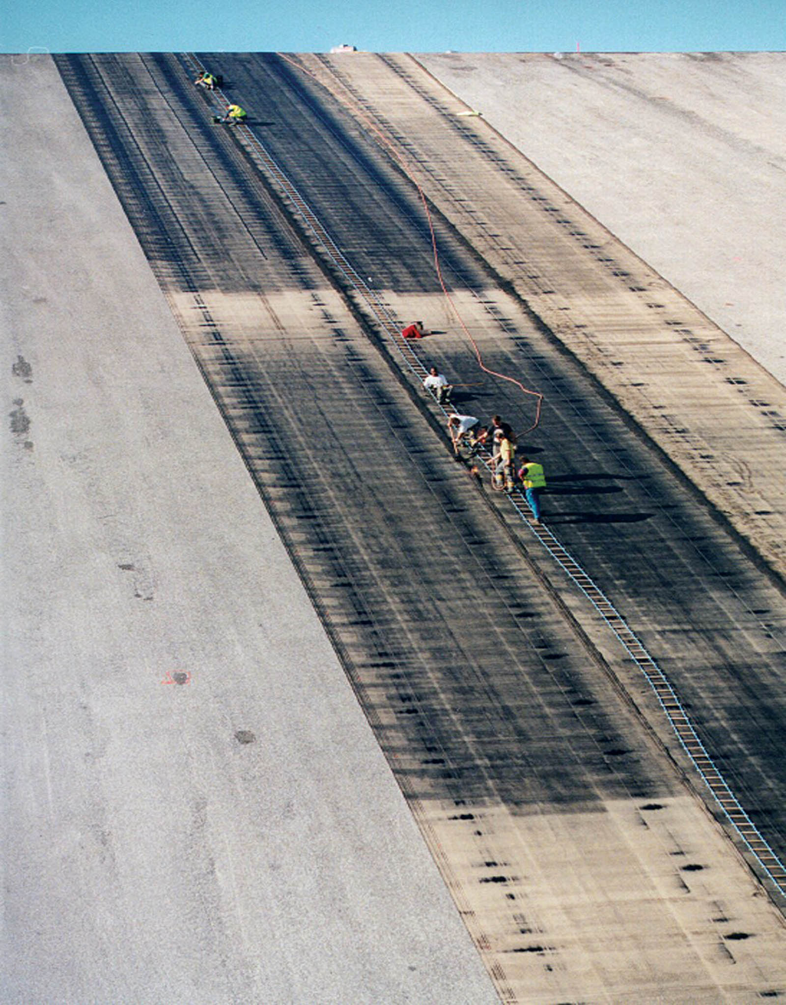
Rolls were lifted and unrolled with a hydraulic beam carried by a 20-ton (18-tonne) track excavator. The hydraulic beam is a patented property of Colas Group, and it allows the driver of the excavator to roll or unroll rolls directly.
Crews laid bituminous geomembrane strips side by side, with an 8-inch (20-cm) overlap of the seams (see Figure 3). The high mass per unit area of the geomembrane reduced the risks of uplift by the wind and creation of wrinkles, which made the welding operations easier.
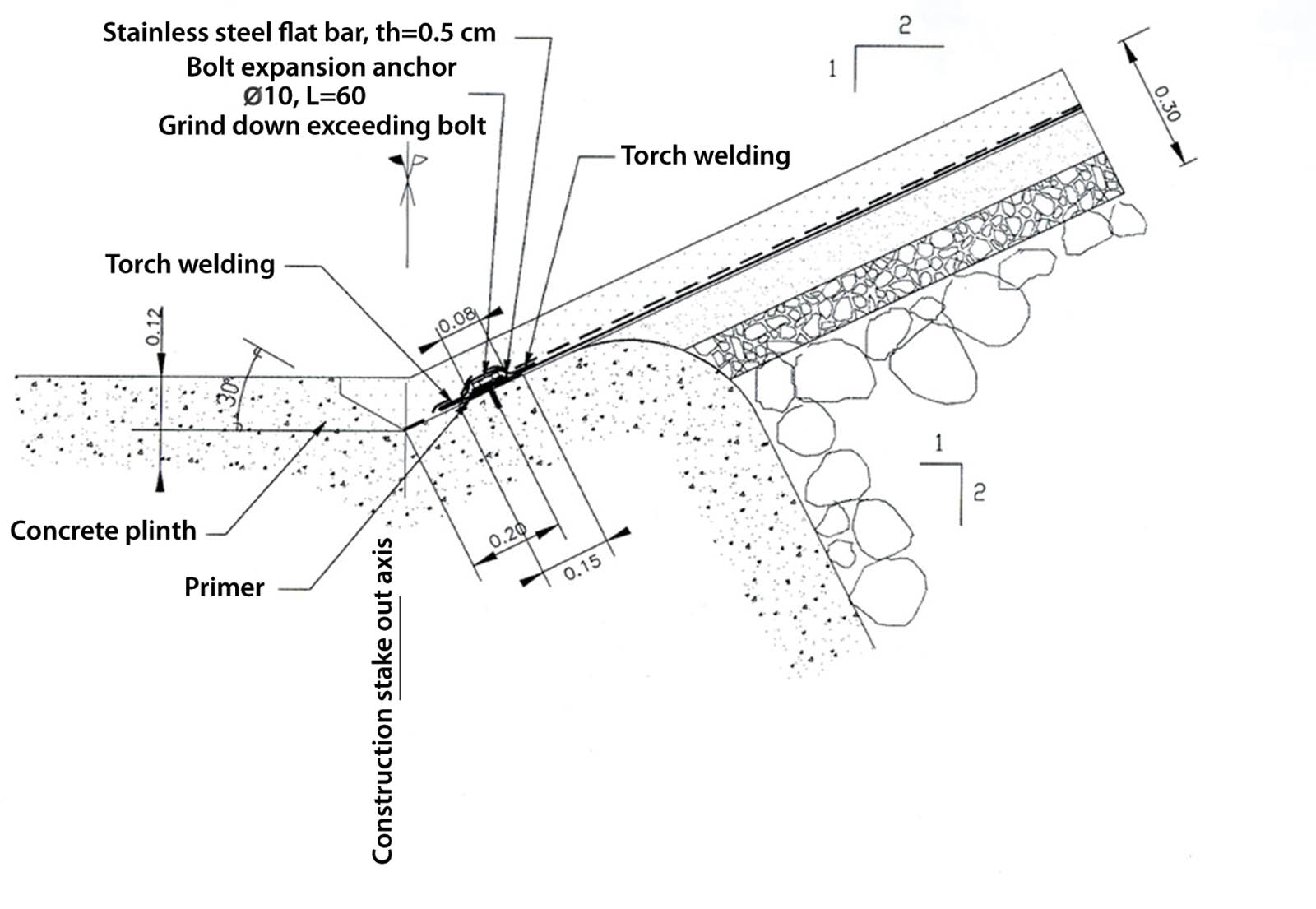
At the foot of the slope and along the whole periphery of the impervious face, the geomembrane was fastened to the reinforced concrete plinth, which is anchored into the rock foundation (see Figure 5). The geomembrane was hot-welded on the concrete surface, which had been previously covered with a tack-primer mixture of bitumen and solvent, then anchored with stainless steel plates bolted into the plinth (see Figure 6 on p. 32).
An anchorage by trench was placed at the top of the slope, of which the size and the distance from the slope were calculated to catch the total tangential effort all along the slope to not be taken by the interface shear strength.
Quality control included three operations:
- Inspectors maintain visual quality control of the seams by monitoring that the geomembrane overlap is at least 8 inches (20 cm). The bituminous geomembrane used has a green indicator line along this distance, making visual quality control easy. Inspectors also verify the bitumen is melted enough to ooze out of the seam at least 0.8 inch (2 cm).
- Crews monitor the finish of the seams by melting the excess bitumen and smoothing it with a trowel to ensure that the edge of the top geomembrane is welded.
Workers also monitor the seams with an ultrasound machine to verify that the weld is extended across the 8 inches (20 cm) of overlap. For this operation, two options are available:
- Spot control, an ultrasonic portable unit is dedicated to ultrasonic control the seam randomly.
- Continuous control using the CAC 94 (Breul et al. 1998) machine. The machine is based upon a measuring wheel, which includes 24 ultrasonic sensors that can detect gaps in the weld as little as 0.3 × 0.2 inch (0.8 × 0.5 cm) at the interface between the two geomembranes.
If a section of welds shows defects, patches extending at least 8 inches (20 cm) beyond the limits of the defects are welded and checked again. Continuous checking of the seams was performed at La Galaube Dam.

A mechanical covering was deemed necessary to protect the geomembrane against damage that could be caused by floating tree trunks (this part of France is heavily forested). This dam produces electricity, adjusting flow through it and thereby quickly changing the water level on the slope.
The slabs were cast in place on the slope in aluminum forms. The concrete was pumped into the forms with a maximum pumping distance set at 200 feet (60 m). Fluidity of the concrete was checked frequently to keep a compromise between its behavior on the slope and its ability to be pumped. Using a reciprocating vibrating drum pulled from the top of the slope, crews vibrated and compacted the concrete. They then filled the joints between the concrete slabs within the range of the water level in the reservoir with an elastomeric binder.
Conclusion
Despite difficult site conditions, due to autumn rains, the project was carried out following a relatively short five-month construction schedule. The waterproofing structure was delivered in November, which allowed the owner to start filling the reservoir before winter. La Galaube Dam is one of the tallest dams in the world in which the upstream impervious face is based upon a bituminous geomembrane.
References
Bianchi, Ch., Rocca-Serra, C., and Girollet, J. (1979). “Utilisation d’un revêtement mince pour l’étanchéité d’un barrage de plus de 20 mètres de hauteur.” Proc., 13ème Congrès International des Grands Barrages, Vol. 1, Commission Internationale des Grands Barrages (International Commission on Large Dams), Paris, France.
Breul, B., Carroget, J., and Herment R. (1998). “Automatic ultrasound field tester for bituminous geomembrane: Development and field results.” Proc., 6th Intern. Conf. on Geosynthetics. Industrial Fabrics Association International, Roseville, Minn.
Davis, C., Lew, M., Perez, A., and Ponnaboyina, H. (2013). “Interface friction testing between soil and a bituminous geomembrane.” Proc., Geosynthetics 2013, Industrial Fabrics Association International, Roseville, Minn., 1–10.
Huynh, P. , Herment, R., and Tisserand, C. (1998). “Écoulement à travers des barrages en enrochements lors de crues de chantier.” Colloque Technique du CFGB, 29(4).
Tisserand, C., Breul, B., and Herment, R. (1997). “Feedback from Ortolo dam and its forerunners.” Rencontres 97: Geotextiles—Geomembrane, Vol. 1, Reims, France.