TEXTILES.ORG

Introduction
Many electric utilities are required by the U.S. Environmetal Protection Agency’s (EPA) recently published Disposal of Coal Combustion Residuals from Electric Utilities Rule to evaluate and address closure options for historical coal ash storage areas. EPA Administrator Gina McCarthy signed the final rule Dec. 19, 2014, and it was published in the Federal Register (FR) on April 17, 2015.
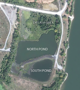
This article focuses on using geosynthetic materials to cap and close a coal ash storage area, before this recent rulemaking, at the Watts Bar Fossil (WBF) plant site near Spring City, Tenn. Originally constructed by the Tennessee Valley Authority (TVA) in the early 1940s, the facility consisted of main plant buildings, a slag disposal area, a coal stock pile, and an ash/stilling pond area (Figure 1). In 1982, the WBF plant stopped power production operations and the TVA terminated the plant’s air permits in 1997.
In 2013, the TVA began the closure process for WBF’s ash/stilling pond area, which included an ash pond formed by a containment dike between the pond and the adjacent Tennessee River. A splitter dike constructed from bottom ash forms the north and south ponds. The north and south ponds contain wet ash material (approximately 90,000 cubic yards in situ). The dry ash area is adjacent to and north of the north pond.
In addition to the coal ash storage area closure, the project included partially lowering the containment dike along the eastern pond edge to reduce the site’s total storage volume and constructing a new concrete box culvert spillway for the site’s future stormwater detention pond. The project goal was to reduce the long-term risk of discharging coal combustion residuals (CCRs) into the Tennessee River.
Closure planning and design
The engineering firm developed pond closure alternatives and designed a cap for ash within the dry ash area. Design considerations included controlling stormwater flow during construction, dewatering activities, de-mucking of ash and stacking during closure operations, constructing a new clay containment dike, and the elements of the cap system. Closure alternatives included designs for a clay cap and using geosynthetics. A geosynthetic cap was selected as the preferred alternative for two key reasons: (1) insufficient amounts of clay material with low hydraulic conductivity being readily available and, (2) construction was likely to occur during winter when it would be more difficult to construct a clay cap.
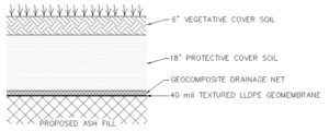
The geosynthetic final cap was designed to consist of the following materials and thicknesses (in order of construction):
- 40‐mil LLDPE geomembrane
- geocomposite drainage net
- 18in. of protective cover soil
- 6in. of topsoil for the support of vegetative cover
- vegetative cover
The cap design included a 5% grade to provide positive surface water drainage. A sod vegetative cover was chosen to quickly stabilize exposed soil and control erosion.
Stormwater flow control was also an issue, as the ash pond drained approximately 185 acres. To address stormwater flow through the site, a diversion ditch was designed through the ash containment area to convey flow to the converted stormwater detention pond. The ditch section also utilized geosynthetics to reduce the risk of contact between coal combustion residuals and stormwater. The ditch was lined with 40-mil LLDPE geomembrane, 10oz. nonwoven geotextile fabric, 6in. of Tennessee Department of Transportation (TDOT) No. 2 bedding stone, and 18in. of riprap protection.
Construction activities and challenges
Construction began with dewatering the ponds. Water from the north and south ponds was pumped through a series of best management practices (BMPs) to reduce the amount of sediment load to the adjacent Tennessee River in compliance with the site’s National Pollutant Discharge Elimination System (NPDES) permit and prevent coal ash discharge.
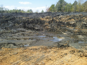
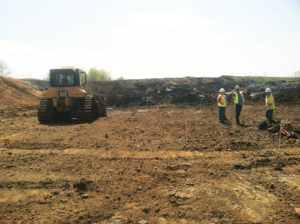
Wet ash within the ponds was then removed through the demucking process (Figure 3). Large amphibious excavators were required for the initial stages of the ash removal process until enough material was removed to enable traditional grading and excavation equipment to be used. The wet ash material was hauled and placed in the dry ash area for further processing and drying. All ash material within the ponds was removed to the clay subgrade (Figure 4).
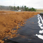
Once the wet ash was removed from the north and south ponds, a clay containment berm was constructed along the southern perimeter of the dry ash area to stabilize the final ash stack as well as separate the ash stack and the final stormwater pond.
When the containment berm was complete, the contractor continued to place ash in the dry ash area in conformance with the technical specifications for compaction and moisture content. The contractor was required to prepare the final top layer of ash with no rocks or ruts that could damage the geomembrane.
During this process, the contractor encountered several soft areas of ash that were not stable enough for equipment traffic. The first instance was the bottom of the diversion ditch constructed to convey upstream stormwater flow through the ash storage area.
For moderately soft areas in the ditch, the contractor over-excavated the ash and replaced it with a clay/ash mixture. For significantly soft areas, the contractor undercut the area approximately 4ft and placed large pieces of concrete in the cut area to stabilize the subgrade.
Before backfilling, No. 57 stone and nonwoven geotextile fabric were placed over the improved areas. Bottom ash from the splitter dike was used as backfill above the improved areas to bring the grade up to the proposed ditch line elevation. As a final step, a sacrificial piece of 40-mil LLDPE geomembrane material was placed along the bottom of the ditch in the improved areas for additional stabilization.
These methods for the diversion ditch proved to be sufficient for eventual geomembrane deployment over the ash. The geomembrane deployment had two phases:
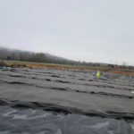
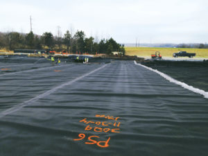
- During a significantly cold period in November 2014, the geomembrane was deployed on the west side of the dry ash area to the crown of the dry ash stack. Special care was taken to ensure that proper welds were performed, including both in-field and laboratory destruct testing. The geomembrane was extended beyond the cap crown so no water could intrude beneath the cap. Anchor trenches were used around the outer cap perimeter to hold the geomembrane in place. A clamping system was used around any pipe/structural intrusions, such as the culverts feeding the diversion ditch and transmission line poles on the west side of the site.
- Extreme cold and frequently wet conditions in December 2014 delayed the second geomembrane deployment on the east side of the dry ash stack until January 2015. Cold temperatures prevented the ash placed on the east side of the dry ash stack to sufficiently dry to support the equipment for geomembrane deployment. To accelerate the drying process, the contractor applied lime kiln dust to the wet ash on the east side of the dry ash stack to shorten the drying time and improve stability.
Following each phase of the geomembrane installation, the contractor continued to place the remainder of the cap system. Geocomposite drainage net was placed on the 40-mil LLDPE geomembrane, followed by approximately 18in. of protective clay cover material. The clay soil placed on top of the drainage net was reviewed and approved by the engineer before placement to verify that no large roots and/or rocks existed that could damage the geosynthetic materials.
The clay material was spread carefully with small equipment to avoid tearing or damaging the geosynthetic materials. After placing the clay cover, a 6-in. layer of topsoil and sod were placed for vegetative cover. Throughout the process, the contractor performed detailed surveys to verify that the appropriate amount of cover was placed on the geosynthetics. Figures 5 (p. 44) , 6 and 7 document the geomembrane placement process.
Conclusion
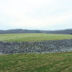
Successful completion of the ash pond closure project at the Watts Bar Fossil site was made possible by the effective use of geosynthetic materials in lieu of a clay cap system. The geosynthetics were effectively deployed under difficult conditions through accommodations of the site design and collaboration in the field among the TVA and the engineering and contracting firms (final configuration—Figure 8).
David Mason, P.E., is principal water resources engineer in the Nashville office of CDM Smith Inc.Jimmy Mullins, P.E., is senior
engineering program manager
with the Tennessee Valley Authority.Steve Whiteside, P.E., is vice president, CDM Smith Inc. (Raleigh, N.C.)
This article is based on presentations made by the authors at the biennial World of Coal Ash 2013 and 2015 conferences.