 TEXTILES.ORG

 By John H. Greenwood
Author’s note
This article is based on a training presentation delivered on Sept. 24, 2014, at the 10th International Conference on Geosynthetics in Berlin, Germany. That talk was itself based on courses given at ERA Technology, Leatherhead, U.K., with Alan Friday, and later at SKZ in Würzburg, Germany, with the participation of Hartmut Schröder, Peter Trubiroha, Helmut Zanzinger, and Bob Koerner. The lectures were then compiled as a 275-page e-book published by SBRCURnet in the Netherlands with an extra chapter by Wim Voskamp. A revised and updated Second Edition has been published in 2015 by SBRCURnet/CRC Press in London, U.K.
This article is not a review of the latest research but it describes the basic information needed whether one is a manufacturer, user, or legislator. For more detail, diagrams, and a full list of references, see this book.
Introduction
Geosynthetics have been in use for about 60 years and have proven themselves remarkably durable. The market, however, requires lifetimes of up to 100 years from polymers that were themselves only invented 80 years ago or less. Polymer scientists have to use their knowledge and experience to assess how these materials could degrade over a variety of uses and environments, what measures can be taken to prevent this, and how durability can be tested in a short time. The words could degrade are carefully chosen: they emphatically do not mean that the materials must degrade in this way.
The essentials
The principal mechanisms of degradation can be listed as:
- mechanical damage
- mechanical loads: compressive, tensile, shear
- weathering
- chemical attack
- biological attack
- temperature (governs the speed of degradation for many mechanisms)
The mechanisms are relatively independent of one another. Start with certain basic information: which geosynthetic is being handled, which environment is it intended for, what is its required lifetime, and what is its end-of-life criterion.
Starting with the geosynthetic:
- Polymer type: a fiber or bulk material, composite, or blend?
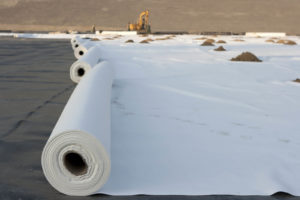
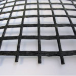
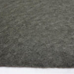
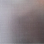
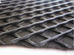
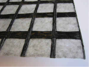
- What form does it take: sheet, woven, nonwoven, grid?
- Is it coated?
- Are there joints or welds?
- What properties are reported for: thickness, strength, hydraulic properties?
- Which additives does it contain?
We then need to know the expected environment, both during storage and installation, and in long-term service, including the following details:
- exposure to light
- ambient temperature, particularly high temperatures: soil temperature in Europe is 10–15 C (50–60 F) at typical civil engineering depths, but can be as high as 40 C (104 F) at depths such as mountain tunnels or behind block walls exposed to direct sunlight. In some cases, the standard testing temperature of 20 C (68 F) is taken as the default service temperature.
- mechanical loads: tensile loads in the plane of the geosynthetic (reinforcing applications) or compressive loads acting perpendicular to it (drainage applications).
- soil: grain size and shape, acidity or alkalinity expressed as pH, presence of metal ions.
oxygen content in the soil (for disturbed earth this is taken conservatively as equalling that of air–i.e., 21%). - saturation of the soil
- biological activity of the soil
Degradation rates can vary considerably. Damage can occur during installation (i.e., before the service lifetime starts, but does not increase after that). Creep-rupture, oxidation, and biological attack occur relatively quickly after long incubation times, making them more difficult to predict. In many cases there will be a variety of lifetimes.
We then need to know the required lifetime. The standard lifetimes set by the European Organization for Technical Assessment (EOTA) are 10, 25, 50, and 100 years. Landfill applications may require even longer times, although infinite lifetime, though desirable, is not an option. Some applications do not require long-term durability. Some examples of design lifetimes are seen in Table 1.
| TABLE 1 | |
|---|---|
| Separator | |
| as construction aid | 0.5-1 year |
| permanent | 80-100 years |
| Filter in drainage applications | |
| replaceable | 10-25 years |
| not replaceable | 80-100 years |
| Reinforcement | |
| in a dam against slip failure | 5 years |
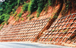
| in retaining structures | 80-100 years |
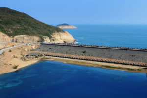
| Drainage, protection | 100 years |
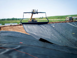
| Geomembranes: dams and tunnels | 100-200 years |
| Landfill liners | 100-1,000 years |
Finally, and more difficult, we need to define the “end of life,” the point at which the material is deemed as no longer fulfilling its function. In general this should be defined numerically, for example:
- 50% loss of strength of a reinforcement
- 2% area of holes in a separator
- 10% increase in permeability of a filter
- 25% reduction in in-plane flow in a drainage material]
- 2% strain in a reinforcement after installation
Loss of strength is often taken as the end-of-life criterion partly because it can be determined with more precision and using smaller specimens than, for example, hydraulic properties.
Ideally, durability would be achieved simply by selection of a suitable material, as can be done by selecting a “robustness class” to eliminate the possibility of damage during installation. Or there will be index tests to assure durability over a certain minimum time. For reinforcements and drainage materials, however, predicted changes in the key properties such as strength or in-plane flow over the design lifetime have to be built into the design.
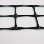
Mechanical effects
Mechanical damage
Mechanical damage is taken as the first example, partly because of its simplicity. This damage generally occurs during installation and, for many applications, the selection of a material of sufficient “robustness” will eliminate any concern. For reinforcements, however, simulated damage tests must be performed to determine the loss of strength during installation so that, effectively, this degraded strength is used in the design. Mathematically, this is done by defining a reduction factor, one of four such reduction factors that, according to ISO 20432, should be applied to the original strength of the reinforcement. These four are:
RFID: installation damage
RFCR: creep-rupture
RFW: weathering
RFCH: environment
and the virgin strength is divided by these factors that are, by definition, each greater than unity.
Creep-rupture
Creep-rupture is the process by which a material under permanent high load may, after time, suddenly break. The strength of the material diminishes first slowly and then more rapidly, such that when it equals the applied load the material will break.
Because there is no intrinsic relation between the applied load and the time to break, it is necessary to perform tests at higher loads and shorter lifetimes to establish this relation and then extrapolate it to lower load and longer lifetimes. If there is a set design lifetime, one can read off the corresponding applied load.
For example, if the design life is 100 years then the creep-rupture diagram might indicate an applied load of 51% of tensile strength. This is the maximum load under which the material is predicted to survive 100 years but rupture one day later. RFCR is then equal to 1/51% = 1.98. In practice this will be multiplied by a safety factor and, since lifetime is sensitive to applied load, the risk of creep-rupture on its own becomes low.
Creep-rupture is also important in geomembranes. In many thermoplastics failure at high loads is ductile, as observed in a simple tensile test. Left on their own under medium loads, however, medium- or high-density polyethylene geomembranes can rupture at low strains, a process that is termed “brittle.” This process has been studied in detail and has led to index tests EN 14576 and ASTM D5397, satisfaction of which will reduce the likelihood of failure. This must be coupled with careful installation to prevent the geomembrane from being under high local stress due to stones or welding, coupled with a design limit such as 3% on the overall strain.
The effect of these local high loads is particularly critical in the presence of certain liquids, a process known as environmental stress cracking (ESC). This is the most common cause of unexpected failure in plastics, partly because the liquids that cause it, such as lubricants and cleaning fluids, appear so benign. These fluids do not attack the polymer in the manner of an aggressive chemical; instead, they swell the amorphous regions of the plastic, allowing the polymer chains to pull out of the solid like spaghetti lubricated with tomato sauce. The index tests mentioned, which include a surfactant, also guard against ESC, but caution is advised if the geomembrane will be in contact with organic fluids and surfactants in particular. Highly oriented polymers—such as the fibers used in geotextiles—are less likely to be subject to ESC.
Creep strain
Applied loads will also lead to permanent strain in the geotextile. In contrast to most metals, this strain continues to increase over time, a process known as creep.
Many tests have been performed on geotextiles under static loads to measure this behavior. For the purposes of design the results can be expressed as isochronous curves of load plotted against strain for different durations. Given a design criterion such as a maximum total strain of 10%, or more likely a limit of 2% strain after installation, together with a design life of, say, 50 years, it is possible from such a diagram to read the maximum load that should be applied to the geotextile. Creep is sensitive to temperature, particularly high temperatures, so the data used should reflect the maximum temperature of the surrounding soil.
Creep strain is equally important in drainage composites, though here the load is compressive and acts perpendicular to the material. Put simply, a drainage composite consisting of an openwork structure between two layers of geotextile will slowly compress under the pressure of the soil, reducing the effective transverse flow. Again, creep tests expressed as isochronous curves will make it possible to define a maximum load given a minimum acceptable thickness (e.g., 80% of initial value) and a set design life (e.g., 50 years). Separate tests are required to relate minimum thickness to the minimum acceptable rate of transverse flow (e.g., 30% of initial value). As shear loads can affect the compression of the drainage composite it may be necessary to include them in the testing.
Weathering
Solar radiation consists of infrared radiation with wavelengths greater than 800nm, visible light with wavelengths between 800 and 400nm, and ultraviolet (UV) light with wavelengths between 400 and 320nm. Because the energy of a photon is inversely proportional to its wavelength and high-energy photons have enough energy to break the bonds in a polymer, UV light is of most concern, even though it makes up only 10% of sunlight or less. UV light is also present when it is cloudy.
The effect of UV light depends on the polymer. In polyethylene and polypropylene it can initiate oxidation, in polyester it can attack the main polymer chain, and in PVC it can lead to elimination of hydrochloric acid (HCl). All geosynthetics are likely to contain additives to reduce their sensitivity to UV, the most familiar being carbon black which absorbs the light and converts it to heat. Heat is generated in the polymer by the entire solar spectrum, resulting in a temperature increase that can be just as significant as wavelength in leading to polymer degradation.
In many applications weathering is important only during storage and installation because in service the geosynthetic will be covered by soil. Accelerated methods exist for testing the susceptibility of geosynthetics for these applications, some methods including the entire solar spectrum and others simulating the UV alone. The European standards relate the outcome of this testing to a maximum duration for exposure on site, for example if 80% strength is retained after testing then a material requiring long-term strength should not be exposed for longer than one month on site. For reinforcement applications it is possible to define RFW. Geomembranes that are exposed to light for all or part of the time in service, such as reservoir and canal liners, present a particular problem because there is currently no short-term test method that will screen them for long-term usage. Their design has to be based on experience and manufacturers’ predictions.
John Greenwood is a consultant based in Ewhurst, U.K.
Reference
Durability of Geosynthetics. CUR Report 243. CUR, Gouda, Netherlands, 2012, pp. 275. Now published (2015) in revised and updated form as Durability of Geosynthetics, Second Edition by John H. Greenwood, Hartmut F. Schröder, and Wim Voskamp. SBRCURnet/CRC Press, London, U.K. approx. 275 pages, ISBN 9789053675991.