 TEXTILES.ORG

The articles in this series encompass all types of geosynthetics and their applications viewed from the context of sustainability. Traditional solutions are compared with geosynthetic solutions from both cost and carbon footprint perspectives. (from the Geosynthetic Research Institute’s 24th conference, 2011)
Abstract
Mechanically-stabilized earth (MSE) berms are increasingly utilized by landfill owners to efficiently create usable airspace for waste disposal.
Since their inception in the late 1980s, MSE berms at landfills have contributed to sustainability by simultaneously allowing geometric maximization of the volume of usable airspace within a given permitted footprint while minimizing the carbon footprint of the berm construction operation by eliminating or delaying the need to site and construct new waste containment facilities and by requiring less time and resources to construct vs. conventional containment berms.
This article will offer a brief historical perspective on MSE berms in waste containment facilities and establish prevalence of their use by solid waste landfill owners, identify the benefits of MSE berms relative to sustainability, and, finally, will quantify conceptually the benefit, in terms of carbon footprint, of an MSE berm vs. a traditionally constructed, unreinforced one. Future considerations of MSE berms at landfills that could further sustainability are also discussed.
Background: MSE berms
Mechanically stabilized earth (MSE) technology consists of utilizing geosynthetic or metallic reinforcing elements in combination with soil and a wide selection of facing elements to create safe, cost-effective grade separations for highways, civil earthworks, and, as in the focus of this article, waste containment facilities.
The first geosynthetically reinforced grade separation structure worldwide was completed in France in 1971 (LeFlaive, 1988) and in North America in Oregon in 1974 (Greenway et al., 1999). In 1985, MSE technology was used for the first time in North America to create useful airspace within a waste containment facility (Seawell and Mattox, 1987).
At this chemical facility near Mobile, Ala., high-density polyethylene (HDPE) geogrids were used as primary reinforcement in combination with polypropylene (PP) geogrids as intermediate reinforcement to create an over-steepened 1H:1V slope 2.5m in height, resulting in 250,000m3 of airspace. This solution was achieved in two months and at only 25% of the cost of a new facility. The same facility was later subject to a second 0.9m vertical expansion that added an additional 75,000m3 of airspace and consisted of near-vertical construction utilizing the same primary reinforcing with a facing consisting of welded wire forms (WWF) and polypropylene facing geogrid.
MSE technology using geosynthetic reinforcing was introduced to the municipal solid waste market in 1996, with the design and construction of the first MSE berm at the Pottstown, Pa., landfill (Ballod and Brown, 2008). Since 1996, MSE berms have been constructed at 11 different landfills in Pennsylvania, with additional construction in New York, Georgia, Maine, New Hampshire, Delaware, Maryland, Massachusetts, Florida, Alabama, Louisiana, Virginia, and Kentucky.
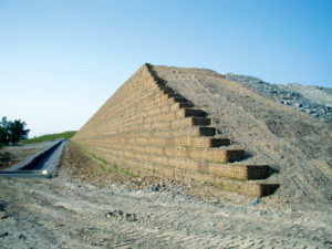
A recently constructed MSE berm is shown in Figure 1.
Continued use of accepted design guidelines, along with a preponderance of literature on all aspects of MSE berms, including stability (Luettich and Quiroz, 2008; Qian and Koerner, 2009) and construction aspects (Brown and Ballod, 2008), have created an environment where the use of MSE berms may continue into the foreseeable future.
MSE berms and sustainability
Current solid waste management strategy is commonly comprised of waste minimization, collection, transfer and treatment, and disposal components (Barron 2001).
Disposal of solid waste in productive manners, such as composting, anaerobic digestion, and waste-to-energy accounts for only a fraction of the overall waste stream, leaving the remainder to be landfilled. In fact, although the disposal percentage of waste landfilled decreased from 89% of the total in 1980 to 54% in 2008, 135 million tons of all MSW generated was landfilled in 2008 (U.S. EPA, 2009). Therefore, the disposal component of the overall solid waste stream remains influential with regard to environmental sustainability. It is in construction of the containment features of the modern solid waste disposal facility that MSE berms contribute to sustainability.
Wikipedia defines sustainability as “the capacity to endure.” Less broadly, but more pertinent, the U.S. Environmental Protection Agency (EPA) defines sustainability as “the ability to achieve economic prosperity while protecting the natural systems of the planet and providing a better quality of life for its residents” (Collin, 2006). Within the latter definition, it is proposed herein that the use of MSE berms at waste containment facilities leads to several sustainability benefits, including:
Reduction of carbon footprint by allowing geometric maximization of the volume of usable airspace within a given permitted footprint—as shown in Figure 2, the use of MSE berms at a landfill can generate the maximum volume of airspace within a permitted footprint.
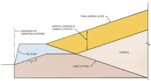
Because the containment berm footprint is minimized, the volume of usable airspace is maximized. As a result of this footprint minimization, the impact as quantified in terms of carbon footprint is also minimized. A simple quantification of the carbon footprint reduction offered by MSE berms is demonstrated in the example presented later in this article.
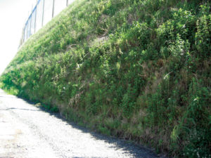
An additional sustainability benefit associated with MSE berms originates from the vegetated face used with most berms (Figure 3). The vegetation serves to reduce the carbon footprint of the containment berm by acting as a natural filter removing atmospheric carbon dioxide.
Ultimately the use of MSE berms at a site must consider all factors that impact their use, including many economic ones (Dickson et al., 2008). For sites at which airspace maximization or carbon footprint minimization is important, MSE berms can be an effective tool.
Elimination or delay in need to site and construct a new facility—in many cases, the use of MSE berm technology has created years of new airspace within the footprint of an existing facility, thereby delaying construction of a new facility. In addition to maximizing the efficiency with which the additional airspace is created, this scenario eliminates disturbance of greenfield sites or other previously undisturbed, natural habitats.
Whether quantified in terms of carbon footprint or any other indicator, this is a sustainability benefit. Reduction in time and resources required to construct a given containment berm configuration, regardless of the airspace considerations at a site, many containment berm configurations can be constructed more efficiently, in terms of time and resources used, using MSE berm technology.
Since carbon footprint is a measure of greenhouse emissions per unit of time, decreased construction time inherently leads to reduced carbon footprint. Although this benefit is dampened on sites where adjacent land is inexpensive and/or time is not a factor, most sites do not have these luxuries.
Quantification of sustainability impact as measured in carbon footprint
The Clean Air Act defines the EPA’s responsibilities for protecting and improving the nation’s air quality. Currently the EPA is considering how best to impose new regulations on industry regarding industry’s annual emission of greenhouse gases (GHG).
One measure of emission of GHG’s is commonly referred to as “carbon footprint” since carbon dioxide is a primary GHG emitted in industrialized countries. The sustainability benefits offered by MSE berms at landfills were presented qualitatively above.
Quantification of these sustainability benefits in terms of carbon footprint can be complicated and difficult because some factors—such as the value of undisturbed natural habitats and reduction in time and resources required—are not easily quantified. However, a simplified calculation can be performed to quantify the benefit of MSE berms compared to traditional landfill expansion even without consideration of the major contributions described above.
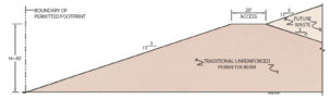
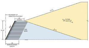
Quantification can be made by considering the carbon footprint of the materials and the associated material transportation required to construct a traditional unreinforced perimeter berm with 3H:1V sideslopes (Figure 4) and an MSE berm with a steepened 0.5H:1V exterior sideslope (Figure 5).
This calculation assumes that the construction will be based on that of a new landfill cell (rather than retrofit), a berm height of 12.2m (40ft), and that the liner materials are the same between the two options.
Construction of a traditional berm requires select backfill to be transported and compacted. In addition to the select backfill and compaction components, materials required for construction of an MSE berm include HDPE primary reinforcement, PP geogrid face wrap and WWF facing with support struts. The materials and the associated carbon footprint for the two options are presented in the flow chart shown in Figure 6.
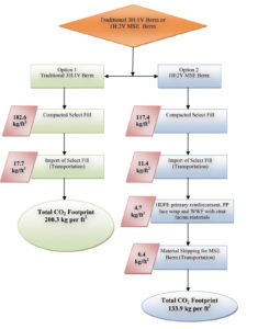
The total carbon footprint (materials and transportation only) of constructing a traditional unreinforced perimeter berm is 200.3 kgCO2 per square foot while the total carbon footprint of constructing a MSE berm is 133.9 kgCO2 per square foot. The carbon footprint is 33% less with an MSE berm as compared to the traditional approach.
Future considerations
The benefits listed above suggest that use of MSE berms at landfills may create sustainability benefits for landfill owners for some time to come. Additional future considerations include:
- Beneficial re-use of waste stream as fill for MSE berm—re-use of materials such as coal combustion products (CCPs) like bottom ash and fly ash, would positively impact the sustainability benefit because what would have ended up as part of the waste stream would instead be used to create airspace. The controlled construction techniques commonly used to construct MSE berms are ideal for CCPs, which commonly must be hydrologically isolated. Pending changes to the regulations regarding CCPs promise to not only increase pressure on the airspace decisions made by landfill owners but also increase the scrutiny under which these materials are handled, ultimately magnifying the sustainability benefit. This approach has been successfully utilized on at least two landfill projects in the U.S. to date.
- As previously described, the MSE berm approach utilizes a near-vertical component made possible by utilizing geosynthetics in composite with soil. One sustainability benefit possible with MSE berms is to take advantage of this near-vertical surface to suspend alternative energy technologies such as solar panels. If this GHG-free method of energy production is used to replace conventional means, the sustainability benefit would be measurable and significant. This approach has been used successfully on at least one landfill project in the U.S.
Conclusions
This article provides a brief historical perspective on the application of MSE berms at landfills and establishes the prevalence of MSE berms in current solid waste management construction. Contributions by MSE berms to sustainability are identified qualitatively and then supported quantitatively on the basis of reduced carbon footprint. Future considerations are also discussed.
Douglas N. Brown, P.E., is director of grade separation solutions, and Willie Liew, P.E., is application technology manager, both at Tensar International in Alpharetta, Ga.
Acknowledgements
The authors want to thank Dr. Robert Koerner for data he shared on the carbon footprint of common geotechnical and geosynthetic materials. The authors also want to acknowledge Joseph Rogers, senior CAD operator at Tensar International Corp., for his efforts in developing the figures used in this paper.
References
Ballod, C. and Brown, D. (2008). “Mechanically Stabilized Earth Berms: Overview at Pennsylvania Landfills,” Proc. 2008 Global Waste Management Symposium, Copper Mountain, Colo.
Barron, J.M. (2001). Environment, Construction and Sustainable Development, Vol. 2 (New York: John Wiley & Sons Ltd., pp. 437–444).
Brown, D. and Ballod, C. (2008). “Construction Details and Related Considerations of MSE Berms at Landfills,” Proc. 2008 Global Waste Management Symposium, Copper Mountain, Colo.
Collin, R.W. (2006). The Environmental Protection Agency: Cleaning Up America’s Act (Westport, Conn: Greenwood Press, pp. 250–253).
Dickson, J.R. and Soong, T.Y. (2008). “Economic Benefits of Using Engineered Berms,” Proc. 2008 Global Waste Management Symposium, Copper Mountain, Colo.
Greenway, D., Bell, J.R., and Vandre, B. (1999). “Snailback Wall: First Fabric Wall Revisited at 25-Year Milestone,” Proc. of Geosynthetics-1999, IFAI, Vol. 2, Boston, Mass., USA, April 1999, 905–919.
Leflaive, E. (1988). “Durability of Geotextiles: The French Experience,” Geotextiles and Geomembranes, Vol. 7, Nos. 1–2, 23–31.
Luettich, S. and Quiroz, J. (2008). “Landfill Stability Analyses for the Application of Mechanically Stabilized Earth (MSE) Perimeter Berms,” Proc. 2008 Global Waste Management Symposium, Copper Mountain, Colo.
Qian, X. and Koerner, R.M. (2009). “Stability Analysis When Using an Engineered Berm to Increase Landfill Space,” J. Geotech. and Geoenviron. Engr., Vol. 135, No. 8, August, pp. 1082–1091.
Seawell, H. and Mattox, R.M. (1987). “An Economical Solution to Increasing the Capacity of an Industrial Waste Facility with a Geogrid Reinforced Dike,” Proc. Geosynthetics-1987, New Orleans, USA, pp. 341–352.
U.S. Environmental Protection Agency (2009). “Municipal Solid Waste Generation, Recycling, and Disposal in the United States: Facts and Figures for 2008,” EPA-530-F-009- 021, U.S. EPA, Washington, D.C.