 TEXTILES.ORG

Introduction
Construction materials continue to be a major source of greenhouse gases (GHG), based on the fossil fuels used in their production.
As the amount of greenhouse gases generated each year continues to increase, there is a conscious effort to provide alternatives with lower carbon footprints. Geosynthetics have always provided cost-effective alternatives to traditional construction materials but now can also provide sustainable alternatives.
One particular construction growth area is stormwater management. The U.S. Environmental Protection Agency (EPA) mandates storage and infiltration on all new construction projects and leaves the design of these systems to the local engineer.
This article reviews the geosynthetic choices and makes comparisons of the amounts of CO2 generated by stormwater systems.
Carbon footprint
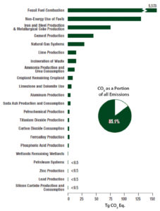
In the U.S., energy-related activities account for more than 85% of human-generated greenhouse gas emissions, mostly in the form of carbon dioxide emissions from burning fossil fuels (Figure 1).
More than half of the energy-related emissions come from large power plants, while about a third comes from the transportation industry. Other significant sources of greenhouse gas emissions in the United States include industrial processes (such as the production of cement, steel, and aluminum), agriculture, forestry, other land use, and waste management.
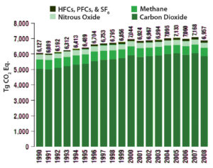
For a better understanding of where greenhouse gas emissions come from, federal, state, and local governments prepare emissions inventories that track emissions from various parts of the economy such as transportation, electricity production, industry, agriculture, forestry, and other sectors. The EPA publishes the official national inventory of U.S. greenhouse gas emissions, and the latest greenhouse gas inventory shows that in 2008 the U.S. emitted slightly less than 7 billion metric tons of greenhouse gases. A million metric tons of CO2 equivalents is roughly equal to the annual GHG emissions of an average U.S. power plant.
Naturally occurring greenhouse gases include water vapor, carbon dioxide (CO2), methane (CH4), nitrous oxide (N2O), and ozone (O3). Several classes of halogenated substances that contain fluorine, chlorine, or bromine are also greenhouse gases, but they are for the most part, solely a product of industrial activities.
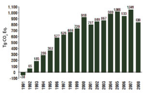
From the pre-industrial era (i.e., ending about 1750) to 2005, concentrations of these three greenhouse gases have increased globally by 36%, 148%, and 18%, respectively, (Intergovernmental Panel on Climate Change, 2007). Figure 2 shows the cumulative change in annual greenhouse emissions from 1990 to 2008.
As shown in Figure 3, 85.1% of all emissions sources of CO2 come from fossil fuel combustions. It is interesting to note that the drop off in GHG emissions in 2008 is related to the economy.
For the purposes of this article, the focus will be on the amount of CO2 created during the manufacturing of various stormwater retention systems and the amount of CO2 created from diesel fuel consumed during construction.
Stormwater regulations
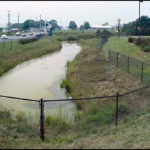
Stormwater runoff is created from rainfall and snowmelts that flow over impervious areas and are not allowed to infiltrate back into the ground and recharge the water table.
Among the first U.S. regulations for stormwater came through the Clean Water Act and the National Pollutant Discharge Elimination System (NPDES) permit program. The NPDES permit program controls water pollution by regulating point sources that discharge pollutants into U.S. waters.
Most states are authorized to implement a NPDES permitting program, and permits may be issued for industrial reasons or for construction purposes.
A point-source discharge is another reason to have a NPDES permit. The EPA (1999) defines a point source as: “any discernible, confined, and discrete conveyance, including but not limited to any pipe, ditch, channel, tunnel, conduit, well, discrete fissure, container, rolling stock, concentrated animal feeding operation, or vessel or other floating craft, from which pollutants are or may be discharged. This term does not include agricultural stormwater discharges and return flows from irrigated agriculture.”
This definition leaves the EPA a broad description for a point-source discharge so there can be little defense against saying the site has no point source discharge.
NPDES permitting along with public knowledge of stormwater issues led local municipalities to adopt their own stormwater ordinances. These ordinances can control many aspects of the construction design, from pipe sizing to maximum amount of impervious cover.
With these stipulations on stormwater management, best management practices (BMPs) are needed to meet or lower current existing conditions.
Types of BMPs
- Infiltration beds—grass swales and porous pavements
- Filtration—such as sand filters and vegetated filter strips
- Retention/detention basins—dry ponds, wet ponds, and inline storage
Structural BMPs are defined as any BMP that involves man-made structure or alteration that would improve the quality of the stormwater. The huge growth of the stormwater market has created a large number of companies and products to meet the requirements and functions of structural BMPs. Some BMPs are used more often than others because of their ease of design and cost.
One BMP used frequently is the lined retention pond. Retention ponds are inexpensive but take a lot of space and have some negative impacts on the environment due to the exposed standing water. Lined retention ponds have the ability to treat large areas of runoff and reduce the amount of sediment that is released to receiving waterways.
An infiltration basin (an unlined retention pond) is another structural BMP often used in site development. The infiltration is usually limited to a location that is not near bedrock or foundations. Infiltration basins can handle a high sediment input but must be designed for proper maintenance. The infiltration basin also recharges the groundwater and reduces the volume released downstream.
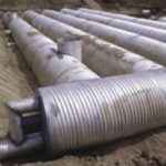
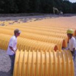
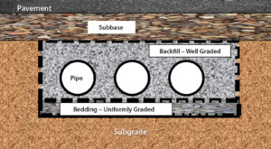
Currently, the most widely used stormwater systems are underground storage systems because they provide the most amount of variability. These systems included stone beds wrapped in filter fabrics, corrugated steel or plastic pipes with a stone envelope around each pipe, half-arch plastic modules backfilled with crushed stone, concrete vaults of various sizes, and multiple types of plastic cubes used to maximize void space (Figures 4a-d).
Current practice
The volume of stormwater requiring on-site storage continues to increase as more impervious surfaces are constructed.
Most regulations require that runoff after construction does not exceed the volume of pre-construction runoff. This creates the need for large volumes of storage on-site.
Traditional storage methods relied on above-ground detention and retention basins. These basins require a large footprint.
In an effort to optimize the value of real estate, there has been a tendency to put stormwater storage systems underground. This trend is seen more in urban areas where the value of real estate is high and the areas available for development are small.
Although there are many types and variations of structural BMPs including detention and retention basins, this article focuses on structural BMPs used for underground stormwater storage. Unlined storage systems infiltrate and allow captured stormwater to percolate into the subsoil, and offer efficient and economical groundwater recharge. In addition to reducing stormwater flows from the site, recharge systems also present water quality benefits through the soil’s natural filtering ability.
Corrugated pipe
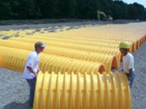
The most commonly used system today is corrugated metal pipe (CMP) and corrugated plastic pipe (CPP). The pipes are connected in rows and tied into a manifold for inlet flow as shown in Figure 5.
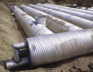
Perforated CMP/CPP is installed and typically enclosed with a nonwoven geotextile design based on site-specific soils to prevent clogging. This provides long-term infiltration and protects against soil piping. The system is then backfilled with the specified soil.
Standard pipe wall perforations (3/8in.-diameter holes meeting AASHTO M-36, Class 2) provide approximately 2.5% open area. This provides adequate recharge flow for most soils.
Minimum spacing requirements between pipes exist to allow for proper backfill, enabling the structure to develop adequate side support. The material specified for backfill is usually the state DOT standard that meets or exceeds AASHTO M-145, A-1, A-2, A-3 granular fill. Closer spacing is possible depending on quality of backfill, method of placement, and compaction methods. Figure 6 is a typical schematic.
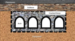
Corrugated arch chambers
One advantage of arch chambers is that they are flexible and can be configured into beds or trenches of various shapes and sizes. These systems can be installed by hand as shown in Figure 7.
These systems require clean angular stone below, between, and above the chambers. The storage capacity is calculated by using both the void space within the chambers and 40% porosity within the stone. The chambers are installed with a minimum 6in.-spacing between each unit and detailed as shown in Figure 8.
This spacing allows for soil arching of the angular stone between arches. The soil arch developed around the chamber provides the structural integrity required to support the pavement system above.
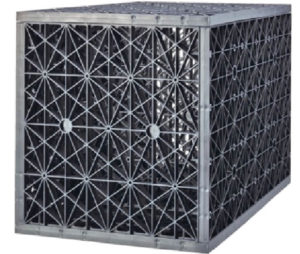
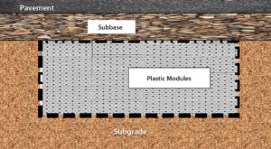
Plastic stormwater modules
Plastic modules are an alternative to corrugated pipe and corrugated arch systems. There are more than a dozen different manufacturers of plastic modules for stormwater storage. One example is shown in Figure 9.
These systems are the most efficient in terms of voids space. They vary from 90% to 95% void space, are easily assembled in the field, are lightweight, and some are made from recycled materials. The high void ratio reduces the amount of excavation required on jobsite and reduces the footprint required to install.
To be more cost-effective, the modular design allows the product to be shipped assembled or unassembled to jobsites. They are lightweight and can be installed by hand, so heavy equipment is not required. The modular units can be stacked or installed in various patterns, making it easier to work around utilities and other obstructions.
Excavations for the plastic modules are limited to the volume required for storage plus any backfill required by the manufacturer. A typical cross section is shown in Figure 10.
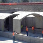
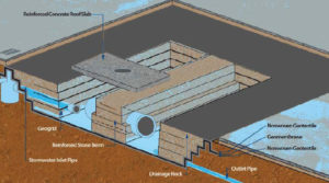
Underground chamber system
A relatively new underground stormwater detention system creates a large storage chamber utilizing geosynthetics, stone, and concrete slabs.
A geotextile or geomembrane liner system is installed within an excavation. Around the perimeter of the excavation, walls are constructed with geosynthetic reinforcement and open-graded stone to create a large underground chamber.
Inlet and outlet pipes extend into the open chamber through the perimeter liner system and wall face. A reinforced concrete roof is installed over the chamber and supported by the perimeter abutment/walls.A schematic of this type of system is shown in Figure 11.
Carbon footprint calculations
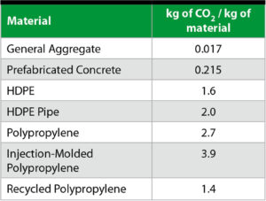
Calculating the carbon footprint of each system requires the breakdown of the materials used in the construction of each system and the amount of earthmoving equipment required to install each system. Once the materials are known, a carbon inventory of each material can be calculated.
The Department of Mechanical Engineering at the University of Bath (U.K.) developed an Inventory of Carbon & Energy (ICE). ICE provides values for the amount of carbon released to produce various materials. (Note that the design life of each material must be accounted for, as well as the amount of material wasted during production, to get a full account of material used.)
Other factors include what type of maintenance is required for each system. Table 1 lists values used to calculate the carbon footprint.
The shipping required for each system must also be part of the calculation.
Diesel fuel for equipment and transportation is 10.1 kg CO2/gallon.
The following assumptions were made for comparative purposes:
- All excavated materials remained on-site.
- All stone required was delivered from quarry within 30 miles.
- All material deliveries were made within a 100–mi. radius.
- All systems are wrapped in a 6.7oz/yd2 nonwoven geotextile.
- All pipes were designed for infiltration.
- Both CMP and CPP are 48in. diameter.
- The volume of stormwater storage is 10,000ft3.
- Recycled plastics used 2.5kg less CO2.
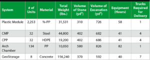
Each manufacturer provides specific guidelines on the installation of its systems. Table 2 was developed using these guidelines and were based on building a stormwater system capable of storing of 10,000ft3 of stormwater.
Once the list of materials for each system is calculated, the fuel required to deliver and install the system must be calculated. These values are then used with the data from Table 1 to create the totals in Table 3.
Conclusions
The results of the calculations for each system show that there can be a vast difference in the amount of CO2 generated depending on what system is selected.

The calculations revealed that the type of material combined with the total weight of material used is the significant factor for the total CO2 generated. Steel and plastics both have relatively high amounts of CO2 in their production that contributes to the overall carbon footprint of the system. Plastics also have high amounts of CO2 in their production; however stormwater modules are more efficient in the amount of material used per unit volume of storage.
It should be stressed that the evaluations did not consider the structural strength of these systems or the cost per unit volume of storage. These factors, along with maintenance and system design life, should also be considered when evaluating various systems.
References
U.S. EPA Greenhouse Gas Emissions, www.epa.gov/climatechange/emissions/index.htmlU.S. EPA 2010 U.S. Greenhouse Gas Inventory Report, www.epa.gov/climatechange/index.htmlInventory of U.S. Greenhouse Gas Emissions and Sinks: 1990–2008: Executive Summary, www.epa.gov/climatechange/emissions/downloads10/US-GHG-Inventory-2010_ExecutiveSummary.pdfHammond and Jones, 2008, University of Bath, Inventory of Carbon and Energy (ICE)Contech Construction Products, DYODS (Design Your Own Detention System)Sheridan, Terence G., “Geosynthetic materials play a major role in new underground stormwater detention system,” Geosynthetics, June/July 2010, pp.34-41