 TEXTILES.ORG

From the Geosynthetics Research Institute’s 24th conference, 2011.The articles in this series encompass all types of geosynthetics and their applications viewed from the context of sustainability. Traditional solutions are compared with geosynthetic solutions from both cost and carbon footprint perspectives. (from the Geosynthetic Research Institute’s 24th conference, 2011)
Introduction
Many geosynthetic erosion control technologies are complete only with a strong marriage to vegetation establishment. Nature’s in-place and well-established success in stabilizing surface soils is the cornerstone in almost every erosion control application.
The geosynthetic response, then, is one of augmentation, stabilization, and water management because they encourage, strengthen, and reinforce the soil/vegetation matrix and direct flows to desired managed systems. In addition, the partnership of natural materials to geo“synthetic” reinforcement in erosion control materials serves to enhance and extend the functionality of the engineered product.
Evaluation of the carbon footprint of these materials begins with an appreciation of the variety of their composite structures, and an awareness of their increasing role in sustainable development.
Erosion control contribution to sustainable development
Sustainable development is performed under several names and methods. The U.S. Green Building Council (USGBC) has introduced standards that measure environmental soundness. As a national group representing several industries, USGBC compiled the LEED (Leadership in Energy and Environmental Design) Green Building Rating System. This rating and certification system outlines specific parameters that must be met for sustainable development; buildings receive points in several categories.
In the stormwater management area, LEED-certified buildings must limit the amount of pollutants and manage the rate and quantity of runoff. Techniques used to meet the LEED standards include incorporating geosynthetic erosion-control measures, green roofs and raingardens, building swales and wetlands, constructing parking lots with pervious pavements, and reusing stormwater for irrigation.
Using water management systems that incorporate geosynthetics to manage and store stormwater as a resource, rather than allowing it to become a nuisance as runoff, has brought opportunity for these geosynthetic applications.
Perhaps the most significant added value that erosion control products bring to any construction project is in avoided costs. For instance, erosion control using low-impact development (LID) techniques that reduce dependence on traditional surface runoff systems and emphasize quick, stable revegetation can produce significant net cost savings.
The proper use and application of erosion and sediment controls in LID help to limit the amount of materials used, reduce the amount of rework for repairs, and help control the extent of the work zone, all of which add value to a project by avoiding costs. The most significant consequence of erosion is loss of topsoil, which hinders the soil’s ability to support plant life and the many associated benefits of mature vegetation.
This can lead to additional landscaping costs, and the increased use of fertilizers, herbicides, and other potential pollutants. Runoff and sediments from these sites can carry unwanted nitrogen and phosphorous into the water system, causing unwanted plant growth that can change the habitat.
In most cases, some form of erosion/sediment control is mandated by the local municipality where construction is planned. Typically modest costs are incurred when erosion control is implemented at the earliest practical point in a project. Also, erosion control product applications can play a role in achieving LEED certification, and is often mandatory in this regard. Erosion control products may also add sustainability by preventing at least two problems:
- If a construction site is in a developed area, the eroding sediment may be going downstream to a location that is negatively affected by the sediment, whether it is a treatment plant that becomes overloaded, a body of water that becomes clogged, or some fluid transport system that becomes choked.
- Eroding soils from the original area limit potential future uses of that area.
Both of these are contrary to the elements of sustainability that encourage us to remember there will be others coming after us. Conversely, increased sustainability may be incorporated into a project by using an organic, decomposable erosion control blanket that may supply a slow release of nutrients for immediate and sustained vegetation growth even in nutrient poor soils. Beneficial soil microbes may develop to add long-term structure and stability to the soil and make nutrients available to plants.
Erosion and sediment control materials
Erosion control materials cover a broad range of technologies including traditional techniques such as blown straw with sprayed-on tackifiers to rock riprap and cast-in-place concrete. More recent innovations in erosion control include rolled erosion control products (RECPs), hydraulically-applied erosion control products (HECPs), and articulating concrete blocks (ACBs).
Similarly there are many types of sediment control materials. Silt fences are a common perimeter sediment control and synthetically reinforced natural fiber matrices called sediment retention fiber rolls (SRFRs) are used as perimeter controls, slope interrupters, and sediment retention check structures to reduce sediment loss on construction projects. Collectively these materials compete with traditional sediment control barrier structures constructed in-place with rock over a geotextile filter.
These different techniques provide different levels of performance and represent different associated carbon footprints. In this article a newer technology, RECPs, are compared to a traditional technique used for channel linings, i.e., cast-in-place concrete.
Rolled erosion control products (RECPs)
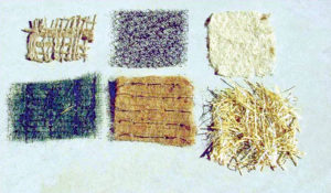
Typically with one or more photodegradable polypropylene nettings as the structural component, temporary RECPs are manufactured using wood, coconut, straw, and hemp fibers.
These products are designed to protect seeded soils and enhance vegetation establishment. This same structural matrix is often combined with fine synthetic in-fill to create a unique 3-D geometry. These products realize a much more robust anchorage to the resulting vegetation, increasing its resistance to erosive forces. A variety of RECP types are shown in Figure 1.
Concrete channel linings
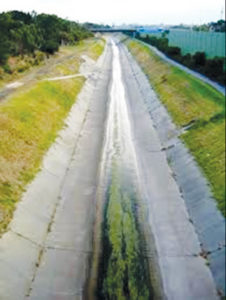
A common traditional erosion-control practice for drainage channels is the concrete-lined, or paved, channel. The concrete lining is typically cast-in-place as a 4in.-thick slab reinforced with a welded-wire fabric.
This type of lining is very erosion resistant, but it encourages faster runoff and discourages vegetation growth, both contrary to good LID concepts. An example of a concrete-lined channel is shown in Figure 2.
Toward consideration of carbon footprints
In search of the lowest carbon footprint among candidate materials, we look for the material that leads to the least amount of carbon in the form of carbon dioxide (CO2) being generated (and presumably being released to the atmosphere) during its life cycle.
This includes manufacturing, shipping, installation, and in-service life. Thus, materials as well as their production and transport requirements, contribute to eventual carbon footprint comparison with other products. Carbon footprint assessment is performed via consideration of several factors:
- extraction of raw materials (e.g., straw, wood),
- transport of the raw materials to the site or the manufacturer,
- production of the primary products (e.g., polypropylene netting),
- transport of the primary products to the manufacturer or the construction site,
- manufacturing of the products (e.g., RECPs),
- transport of the products to the construction site, and
- integration of the products (e.g., distribution, installation, laying).
The carbon footprint, or CO2 emission, can be described either as the embodied energy and reported as megajoule (MJ) per kilogram (kg) of material or as embodied carbon and reported in kg CO2 per kg of material. The embodied energy value is considered to be somewhat more accurate, but both represent the environmental impact of that material.
Table 1 shows the embodied energy and carbon values for a variety of materials used for erosion control.
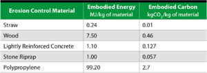
The values generally represent “cradle to factory gate” boundary conditions. Additional carbon footprint must be added to account for transport to the site and material installation. This variety of erosion control materials is significant when considering the carbon footprint implications of erosion product life cycle and use.
CED (cumulated energy demand) in life cycle assessments
The multitude of environmental impacts leads to an associated complexity in the data collection process and to complex methods for evaluation. If a large part of the environmental effect results from the provision and consumption of energy, the cumulated energy demand (CED) may be used as a first rough check of “short life cycle assessment.”
In this way the CED is a first indicator for an evaluation of the energy, transport, and material services. Even though the CED also requires data, the energy data may be collected and standardized easily (Hammond and Jones, 2008).
The cumulated energy demand (CED) is stated with the units:
- MJ/kg in relation to the product.
- MJ/m3in relation to the compacted/stabilized soil.
- MJ/m2 in relation to the compacted/sealed surface.
With regard to rolled erosion control products (RECPs), the polypropylene material has a very high embodied energy and carbon. Concrete and wood have moderately high embodied energy and carbon. Natural fibers and rock have lower embodied energy and carbon. Natural fiber erosion blankets use a relatively small amount of netting and synthetic polypropylene fiber-filled blankets use slightly more. The following case history illustrates the carbon footprint result of replacing a traditional concrete lining with a RECP.
Case History: Comparison of carbon footprints for a concrete-lined vs. RECP-lined channel
A California-based power company expanded its geothermal operation including a new well pad for a geothermal drilling site and an access road.
As part of the long-term stormwater pollution prevention plan, the site plan called for a long concrete V-shaped swale channel to carry excess runoff water off of the site. While the county was mainly concerned with the high cost associated with the installation of a concrete lined swale, they were also concerned with the potential erosion and litigation problems that could occur if the swale wasn’t properly designed to meet the performance needs. The site was characterized by an erosive shale-based soil that needed protection from runoff water that would fill the swales after storm events. The swale also needed to be able to withstand strong runoff velocities.
The county’s public works department and the regional water quality control board were involved with the site design and wanted to ensure that the swale had the ability to negate any erosion as well as result in clean water leaving the site.
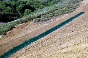
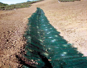
The project contractor superintendent sought alternatives to the concrete swale. After analyzing the project, a RECP lining was selected as a replacement for a concrete-lined design (Figure 3).
The design of the RECP, with its 3-D permanent netting structure and permanent polypropylene fiber matrix, offered both temporary and long-term erosion control and vegetation reinforcement. By replacing the concrete with a RECP, the swale would be able to be vegetated and led to a more aesthetic design as well as easier long-term maintenance.
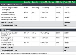
Because the RECP was a porous product it allowed for water infiltration, thus reducing overall site runoff and eliminating the need for extensive water control. Table 2 demonstrates how the RECP greatly reduced the carbon footprint of the application by reducing the fossil fuel and natural resource consumption.
Conclusion
The example in this article summarizes a carbon footprint accounting of a geosynthetic erosion control application within comparison to a hard armor concrete competitive erosion control product.
More examples are available that provide even more of a pronounced carbon benefit when compost or natural fiber matrices are employed in rolled erosion control products. Such innovative products play an important role in the continued need for sustainable development achievement and the associated environmental care.
Sam Allen, vice president at TRI/Environmental Inc., is a member of the Geosynthetics Editorial Advisory Committee.
C. Joel Sprague is a senior engineer at TRI/Environmental Inc.
References
Egloffstein, T.A., Heerten, G., von Maubeuge, K.P, “Comparative life cycle assessment (LCA) for clay geosynthetic barriers versus clay liners and other sealing systems used in river dykes, canals, storm water retention ponds and landfills,” 3rd International Symposium on Geosynthetic Clay Liners, 2010.
Hammond, G. and Jones, C. (2008), “Inventory of Carbon and Energy (ICE) version 1.6a,” University of Bath.
Stevens, P.A., “How to Calculate the Carbon Footprint of Trucking Shipments,” Ezine Articles.