 TEXTILES.ORG

Design, construction and fire damage mitigation
By Nathan M. Lichty, Stephan M. Gale and Timothy P. Bendell
Demolition of the Hubert H. Humphrey Metrodome stadium in Minneapolis, Minn., occurred in 2014 and subsequent construction of U.S. Bank Stadium (Figure 1), the home of the Minnesota Vikings and host of the 2018 Super Bowl, occurred between 2014 and 2016 on the same site.

The stadium architect provided a concept-level drawing of a reinforced soil slope (RSS) stress relief wall in the project plans. The purpose of the RSS was to allow the 30-foot (9.1-m) tall south stadium foundation wall to be constructed with concrete masonry units (CMU) on a spread footing foundation rather than a thick cast-in-place concrete wall on deep foundations that would have been required to support the lateral earth pressures. Of concern was the foundation bearing soils. The cast-in-place concrete wall would have had to be supported on drilled piers to competent bedrock because of the low bearing capacity for the moderately weathered limestone bedrock at the bottom of the wall. The more cost-effective CMU wall could be supported on a spread footing over the bedrock, resulting in a $5.5 million savings.
The concept drawing showed a 5-to-7-foot (1.5-to-2.1-m) gap to be formed at the top of the RSS that would be spanned with a precast concrete panel, thus leaving a permanent void space between the stress relief wall and the stadium foundation wall.
From the concept-level drawing, the authors designed the RSS and worked with the project civil and structural engineers, the stadium general contractor, and the RSS/earthwork contractor to alter the building excavation and utility plans to facilitate RSS construction. Design and construction challenges included RSS geometric constraints, geogrid reinforcement diversion around horizontal and vertical utility structures, diversion around tower cranes, and diversion around pedestrian bridge piles and pile caps.
The RSS was completed during the later phases of U.S. Bank Stadium construction in the spring of 2015. Shortly after RSS completion and before precast panel placement, an approximately 30-foot (9.1-m) long portion of the RSS face was damaged from heat created by a fire that started as a result of welding sparks falling from roof construction and igniting the polystyrene insulation installed along the building CMU foundation wall. The authors and the RSS contractor investigated the fire-damaged portion of the RSS. The wall was repaired with percussion driven anchors, a welded wire mesh and a shotcrete facing.
Initial RSS design
Located in downtown Minneapolis, the stadium site is in a constrained location adjacent to Chicago Avenue that required a minimal excavation width for installation of the RSS geogrid reinforcement. The stadium plan included a 700-foot (213.4-m) long RSS stress relief wall concept-level design. The RSS would be subjected to relatively large surcharge loads from temporary shoring and mobile cranes during construction and from emergency service vehicles long-term. The RSS was designed to support a 15-kip (66.7-kN) point load due to temporary shoring placed during construction, an 800-psf (38.3-kPa) distributed load from large construction/maintenance equipment, and a 4,500-lb/ft (6.1-kN/m) strip load from the void-spanning concrete slab and potential emergency service vehicles.
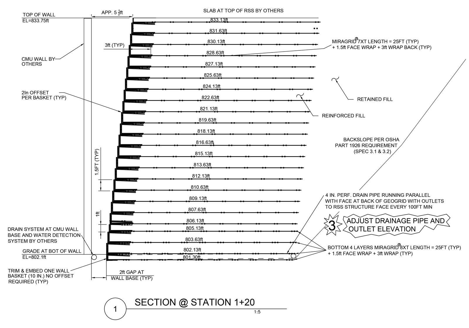
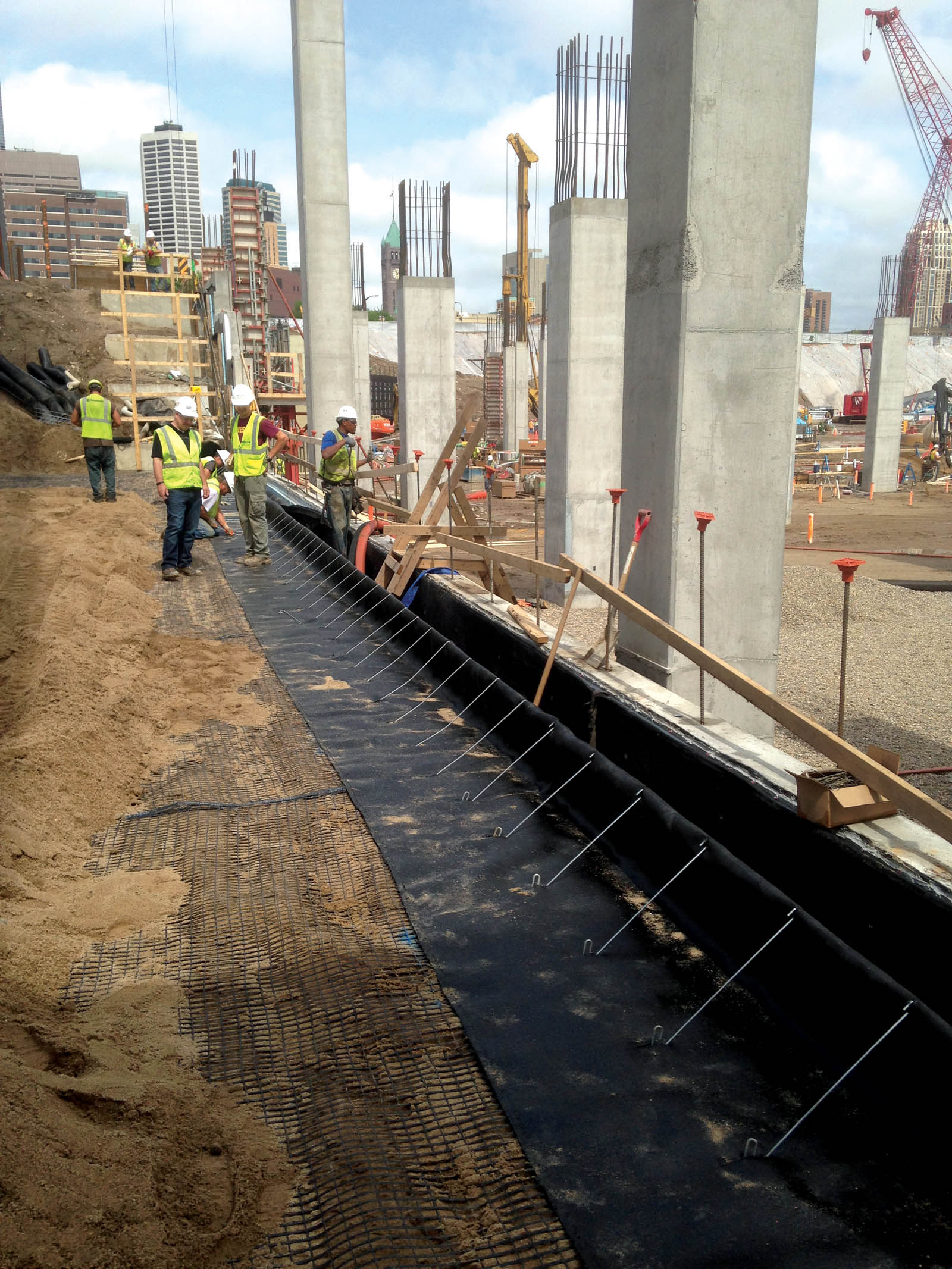
From these limiting factors, it was determined that a granular material with a friction angle of at least 35˚ would be required for the RSS reinforced fill, which would help reduce the geogrid lengths and the subsequent excavation width required while still supporting the high surcharge loads from crane operation during construction. Internal and external stability analyses indicated that a uniaxial geogrid product, placed at 1.5-foot (0.5-m) vertical intervals at lengths equal to 90% of the RSS height, was required. At the RSS face, a relatively high-tenacity polypropylene multifilament woven geotextile was used as a wrap to retain the granular material. The geotextile was placed inside of a 1.5-foot (0.5-m) tall galvanized welded wire basket that was used to help form the facing. Each basket was placed at a 1-inch (2.5-cm) horizontal offset to keep the RSS tolerance within the 5-foot (1.5-m) maximum void span length at the top of the RSS. A typical RSS section is shown in Figure 2, while the RSS facing is shown in Figure 3.
RSS design and construction challenges
There were some unique design and construction challenges associated with the RSS.
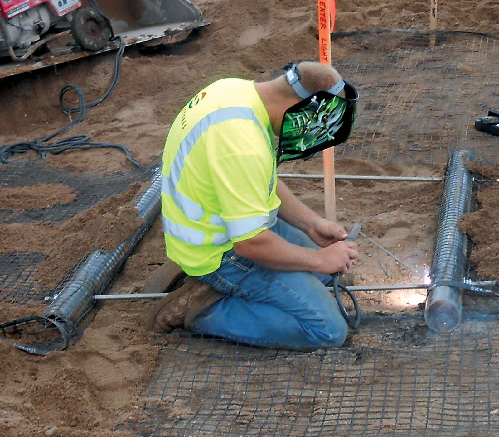
A portion of the RSS had to be constructed to align with a descending chevron concrete structure that was supported on grade beams on H-piles. The RSS had to turn multiple 90˚ outside corners and ascend at a specific angle to be able to support the chevron concrete structure. Multiple horizontally oriented storm and sanitary pipes were required to be installed through the face and RSS reinforced fill. The RSS geogrid reinforcement had to be diverted around these horizontally oriented pipes. Several vertically oriented storm sewer inlets and manholes were also located within the RSS fill. A geogrid diversion system, consisting of structural bars and threaded rods, was designed to divert the tensile forces in the geogrid reinforcement to opposite sides of the structure where the geogrid could be extended again. Figure 4 shows a geogrid diversion system being assembled.
A pedestrian bridge to an elevated stadium entrance was also planned along the southern portion of the stadium. The piling and pile caps that supported the pedestrian bridge were located within the reinforced backfill. The authors required that the piling be installed prior to RSS construction so that the geogrid reinforcement could be diverted around the piles during RSS construction. Where the concrete pile caps interfered with the geogrid extent, the geogrid was mechanically connected to the concrete pile caps using a pipe and rebar anchor system that was designed to transfer the tensile forces in the geogrid to the concrete cap and piles. An anchor hook was drilled and grouted into the pile cap, a 3-inch (7.6-cm) diameter pipe installed in the hooks, and then the geogrid was wrapped around the pipe and extended to the required runout length. Figure 5 shows this system.

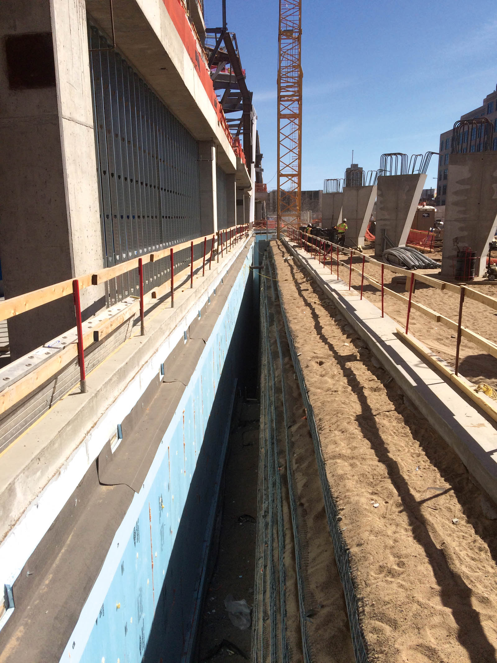
The 5-foot (1.5-m) void at the top of the RSS wall was designed to be spanned with precast panel planks tied to the stadium foundation wall and then supported on a small footing on the RSS. Figure 6 shows the completed RSS wall with the footing for the precast concrete plank in place.
RSS fire damage and remediation
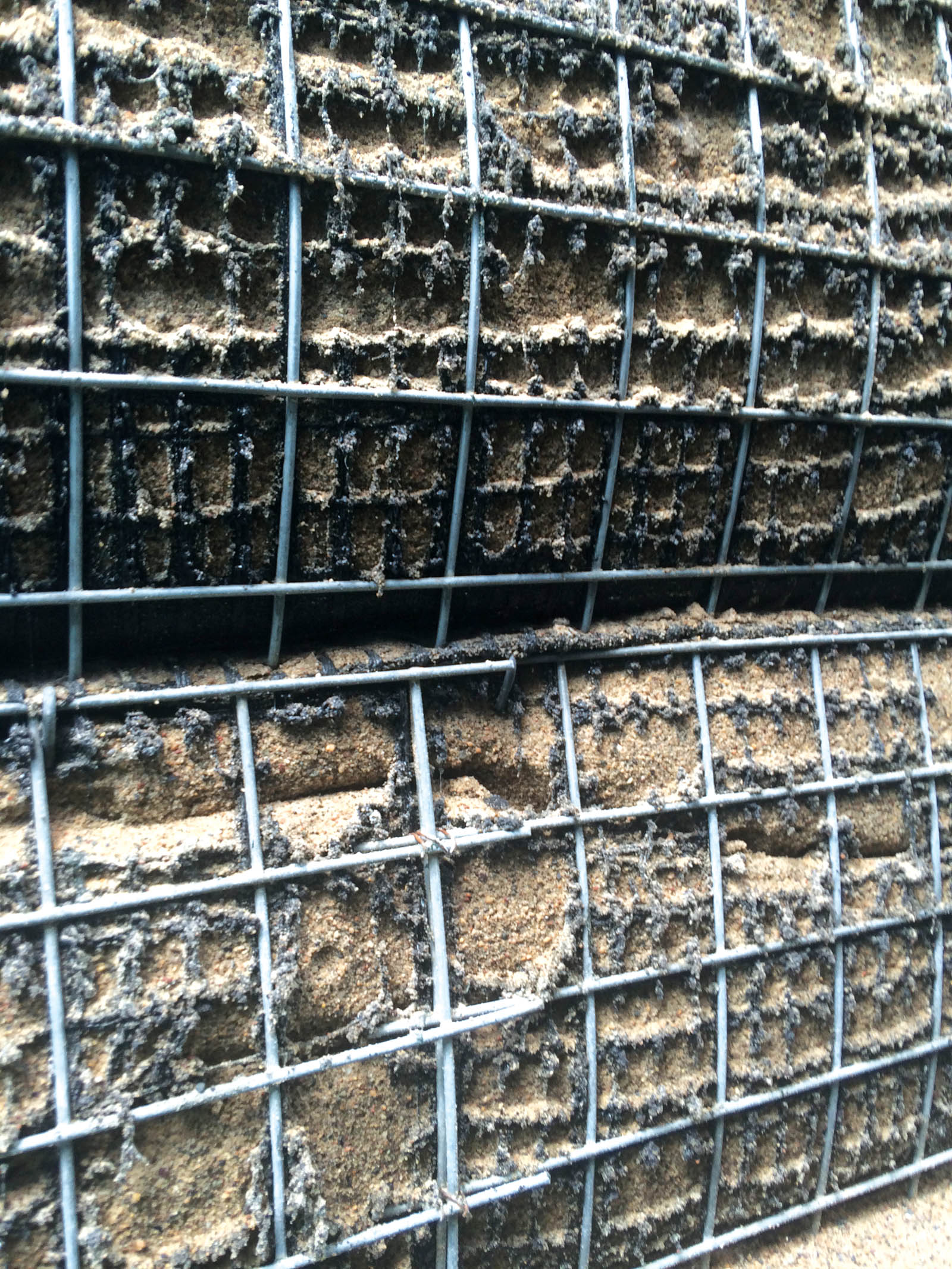
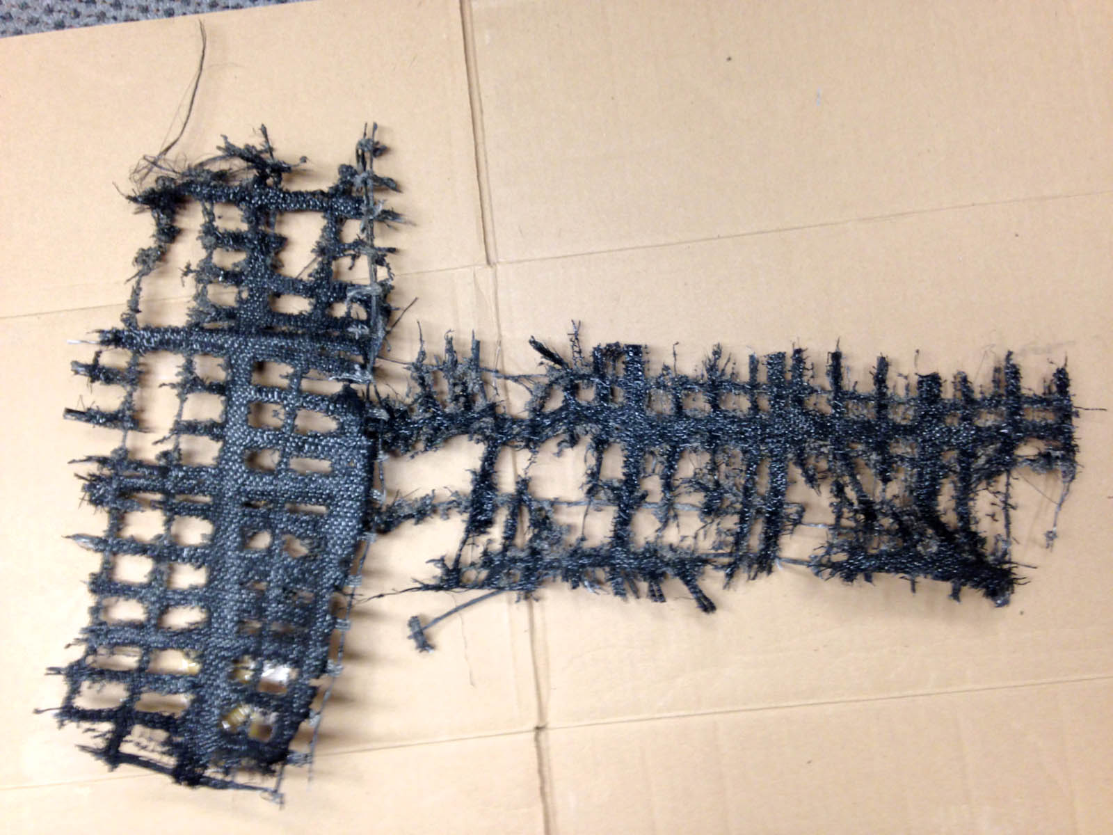
The RSS wall was nearly completed in the summer of 2015 with the void still open when, on a Friday morning in mid-July, welding sparks from overhead roof construction ignited the polystyrene insulation board installed on the outside of the CMU foundation wall. The CMU wall is located 3 feet (0.9 m) away from the RSS wall face at the bottom of the wall. The resulting fire sent a black cloud of smoke high into the sky. The fire was quickly extinguished with the assistance of an on-site water truck being used for dust control, with final fire resolution by the Minneapolis Fire Department. An approximately 30-foot (9.1-m) wide portion of the RSS wall appeared to be damaged. The authors observed the damage within a few hours of the fire. The polypropylene woven geotextile face wrap and the polyester geogrid reinforcement that wrapped around the face had melted over a 30-foot (9.1-m) horizontal distance and over the full 30-foot (9.1-m) height of the RSS wall. The granular fill was starting to slowly slough out at the face in the damaged portion of the RSS. The Material Safety Sheets identified that the geotextile polypropylene fiber melts at approximately 325oF (163oC), while the polyester geogrid melts at 400oF (204oC). These temperatures were apparently exceeded near the RSS face during the fire, since both products had melted to some degree. Figures 7 and 8 show the RSS fire-damaged facing.
Geogrid samples were cut out of the fire-damaged portion of the RSS at various distances back into the fill from the face to determine the extent back into the RSS the geogrid reinforcement had been compromised. The forensic ASTM D6637 testing indicated that the geogrid reinforcement was only damaged within approximately 1 foot (0.9 m) of the RSS face. Based on these test results, it was determined that remediation would only be required at the RSS face and that complete excavation and reconstruction of the RSS within the fire-damaged area was not necessary.
The facing remediation plan selected consisted of placing a new welded wire mesh on the face, shotcreting the face, and then installing a series of 3-to-5-feet (0.9-to-1.5-m) long Gripple percussion driven anchors within the fire-damaged area. The anchors were installed at a 3-foot (0.9-m) triangular spacing. The remediation measure was designed assuming that the outer 3 feet (0.9 m) of the geogrid and the geotextile wrap had been compromised.
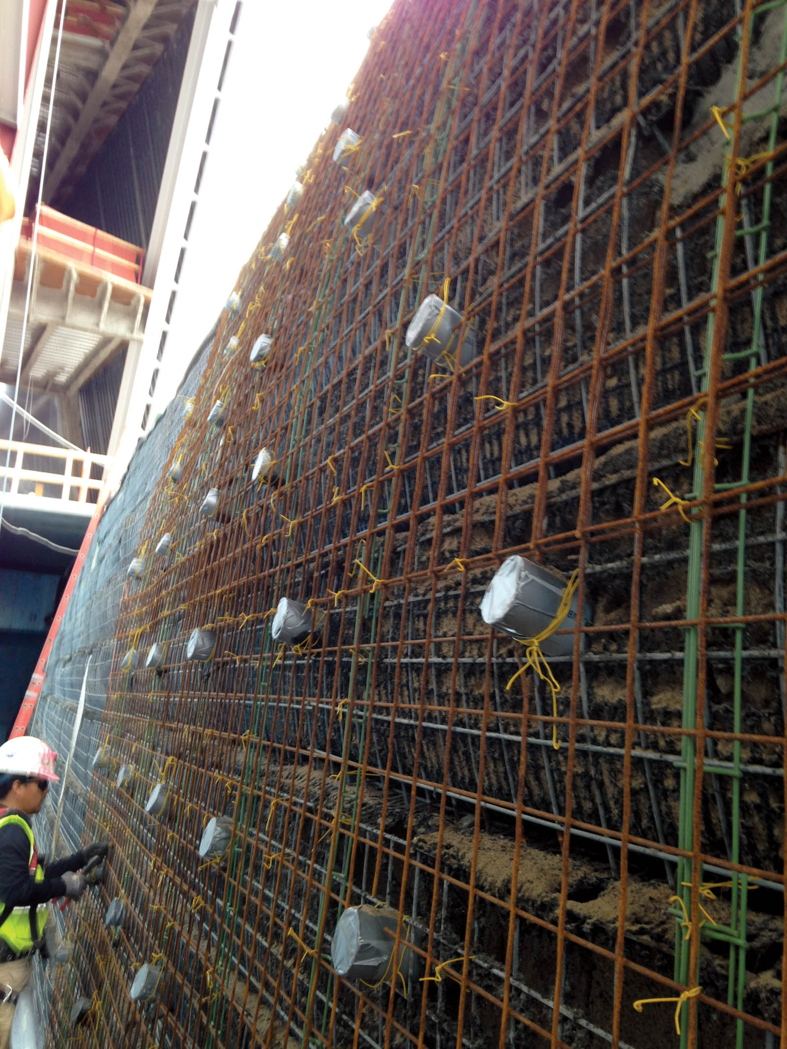
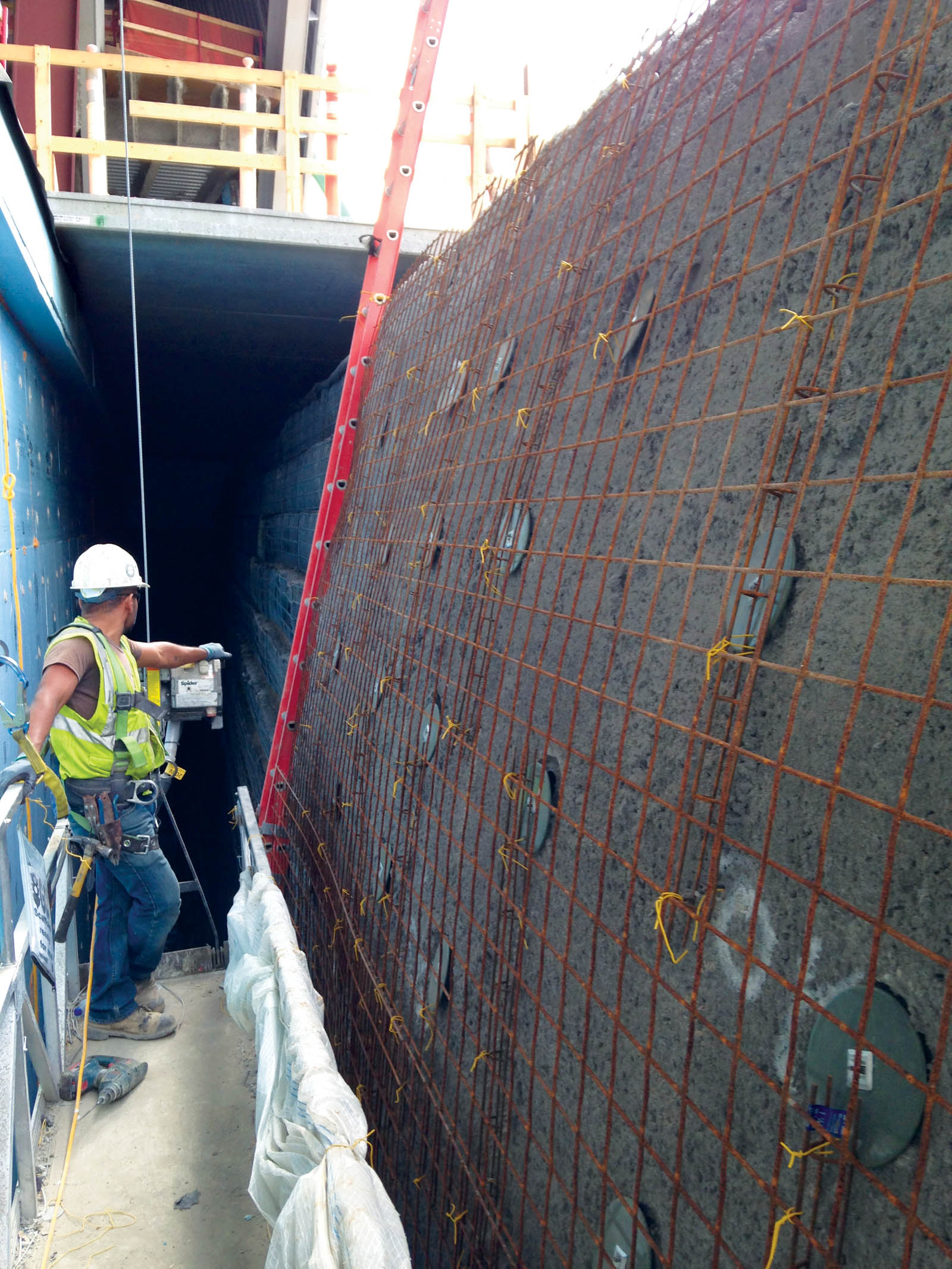
The anchors and shotcrete were installed from a swing stage by a construction crew that was experienced in confined space concrete work. Two 3-inch (7.6-cm) thick layers of shotcrete, reinforced with W4.0 × W4.0 welded wire mesh, was applied over the damaged RSS face. The design required that the percussion-driven anchors be installed with a hammer drill after shotcrete installation. Anchor proof testing indicated that all anchors exceeded the required pullout capacity. The RSS fire damage remediation was completed in September 2015. Figures 9 and 10 show the wire mesh installation and the sleeves for the anchor installation near the top of the RSS face.
Conclusion
The below-grade RSS stress relief wall, constructed along the southern portion of the U.S. Bank Stadium, with a 5-foot (1.5-m) void at the top of the RSS, was conceived as a substitute for a 30-foot (9.1-m) tall cast-in-place concrete foundation wall on a drilled pier foundation. The cost savings was estimated at $5.5 million.
The RSS wall design required that the site excavation, grading and utility plans be altered. Implementation presented unique design challenges. Some of these challenges included geometric constraints, horizontal and vertical obstructions within the RSS reinforced zone, and fire damage on a portion of the RSS facing. Gale-Tec Engineering Inc. and TenCate Geosynthetics worked with the structural and civil engineers as well as the general and earthwork contractors to address these unique challenges complementary to other portions of the stadium site construction.
Nathan M. Lichty, P.E., M.ASCE, is a project engineer with Gale-Tec Engineering Inc.
Stephan M. Gale, P.E., D.GE, F.ASCE, is the president and founder of Gale-Tec Engineering Inc.
Timothy P. Bendell is SRW Segment Manager–Engineered Structures for TenCate Geosynthetics.
SIDEBAR: Project Highlights
U.S. Bank Stadium RSS wall
RSS Wall Designer:Gale-Tec Engineering Inc.
Architect:HKS Inc.
General Contractor:Mortenson Construction
Earthwork and RSS Contractor:Ames Construction
Shotcrete/Remediation Subcontractor:PCI Roads
RSS Geosynthetics Manufacturer:TenCate Geosynthetics
RSS Geosynthetics Supplier:ASDCO Construction Supply