 TEXTILES.ORG

By Rohit Sati | Layfield Geosynthetics
Backfilling geomembranes helps protect your liners from environmental and mechanical damage. It can also improve the impermeability of the liner system.
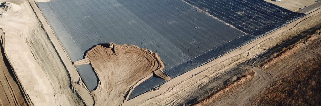
Almost all liner materials can benefit from using a backfill cover. Properly designed backfill systems can extend the life of your geomembrane liner to the maximum extent possible. Let’s discuss some items to consider during your selection and placement of backfill. Backfill can often be selected from locally available fill materials. Processed or natural non-cohesive soils, such as gravelly sand, screened sand, pea gravel and well-graded cohesive soils, such as clayey silt or silty clay, are some examples of suitable backfill materials. These fill materials can have larger stones as long as no crushed or shattered rock fragments are present.
The first “rule of thumb” for included stones (round) is that the largest stone or maximum size of any of the gravel inclusions should not be greater than 25 mm (1″). In addition, all gravel inclusions that are angular or have sharp or chiseled edges should be removed from the backfill either at the source or during placement.
The second “rule of thumb” for backfill over a liner is that the soil material(s) should be capable of compaction or consolidation with light to medium-duty smooth drum or vibratory plate compaction equipment and should not require extensive reworking, conditioning, and kneading. Materials that contain lumps, clods, or cemented inclusions that require additional compaction effort to break them down are likely unsuitable. Clean or screened sand is the ideal backfill material. However, the local availability of fill materials and slope stability requirements will dictate what fill material will be used.
Cohesive backfill materials, such as clay that are placed directly over the liner, can improve the liner system’s performance. Studies have shown that when clay is in intimate contact with the liner, the individual performance characteristics of both layers are additive. This means that, from a permeability perspective, the combined system performs better than the sum of the individual elements; therefore, leakage rates through minor defects in either the liner or the clay backfill are dramatically reduced compared to each as a stand-alone system.
In certain instances, locally available backfill material will contain significant amounts of oversized gravel and/or sharp, angular gravel. Even though these types of backfill material can be easily worked and compacted to form a uniform, level backfill surface, the sharp stones and oversized gravel may damage the liner without the earthwork contractor’s knowledge. In cases such as these, it may be necessary to protect the liner with a cushion layer of sand. This cushion backfill layer should be in the order of 50 mm to 150 mm (2″ to 6″) thick, depending on the specifics of the installation, and should be compacted. In locations where sand is not available, a medium to heavy-weight geotextile may be used as an alternative.
A final note on the selection of fill materials: large clay lumps, roots (organics), and frozen lumps of fill should be avoided. The fill must be “free-flowing,” and placement methods that push fill onto the liner must be able to “roll” the fill ahead. This becomes very difficult in winter conditions where frozen fill and/or freezing conditions might occur. Watch carefully that the fill being placed does not “slip” or shear along the top of the liner. If this type of slippage or shearing occurs, check for damage under the backfill. Ensure that the fill rolls onto the liner so that shear forces are not transmitted to the liner.
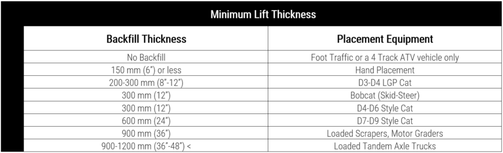
The attached table contains the minimum lift thicknesses for the initial lift of the backfill. These minimum thicknesses are given as guidelines. Conditions may vary from site to site, and the engineer in charge of the project may authorize different minimums from the numbers shown here. Sound engineering practice must be exercised, and appropriate equipment and methods must be selected if thinner initial lift thicknesses are to be considered.
Backfill placement usually depends on the equipment used to place the fill rather than the liner material. HDPE is a special case and requires a minimum of 450 mm (18″) of backfill due to the height of its slack wrinkles, which can reach 150 to 200 mm (6 to 8″) high. Each type of equipment has a specific ground pressure and weight that requires a different minimum backfill thickness for liner protection. The initial lift thickness must be of a minimum to protect the liner from the equipment used. If backfill compaction is required, smaller equipment may be necessary to place the initial lift. Larger equipment can then be used for the second and subsequent lifts.
The usual method for placing a thin backfill is to build a road through the pond of at least 600 mm (24″) thickness (depending on the type of backfill material and equipment used, a road up to 1200mm (48″) may be required). Loaded trucks may use this road to deliver the backfill to the correct area. A wide pad Cat (bulldozer) or other small piece of equipment then operates perpendicular to this road and pushes the backfill off the road to create a thin lift throughout the pond. The Cat operator must always exercise caution and ensure that the fill rolls off the bottom of the blade and does not introduce a shearing force along the surface of the liner.
Care should be taken during all aspects of backfill placement. A spotter should be positioned beside the Cat to monitor the placement and thickness of the backfill on the liner. Your spotter can usually identify problems during placement that the Cat operator may not see. During backfill operations, there are a few things to look out for. First, skid-steer equipment, such as a Bobcat, must refrain from making sharp skid turns on top of the liner or on top of a thin lift of backfill. Sharp turns with one tread (set of wheels) locked can damage the liner. Skid-steer equipment must make long sweeping turns at all times.
Care must be taken to maintain the appropriate fill thickness beneath a vehicle. Vehicles should not travel on the unprotected liner at any time (4-track ATVs may be acceptable). The ground pressure or tire pressure of the vehicle can be used as a guide to minimum backfill thickness. Wheeled vehicles with tire pressures around 200 kPa (30 psi, such as Bobcats and pickup trucks) can operate on a minimum thickness of about 300mm (12″). However, all trucks with tire pressures of 500 kPa (80 psi) or higher should have at least 900 mm (36″) of fill beneath their wheels.
Place fill from the bottom to the top of the slopes. Standing water should be removed prior to placement of the backfill. Your backfill depth can be checked by carefully hand-excavating small test pits as required. Special grade stakes that rest on top of the liner can be manufactured. These stakes, usually an upside-down wooden “tee,” must be removed prior to backfill. Do not cover grade stakes with backfill. A more effective method of grade control involves the use of laser level survey equipment that eliminates the need for survey stakes. All measurements of grade are to be referenced to the actual liner elevation within the containment area.
The most significant problem when backfilling in cold weather is frozen fill. It may be necessary to heat your backfill stockpile or make provisions for heating and hoarding at the backfill location. Layfield can supply large covers suitable for applying heat to a fill stockpile or for hoarding if required. Ice lumps in the backfill can also cause damage. Frost, or a dusting of snow on the liner, does not always have to be removed; however, it becomes much more challenging to roll the backfill into place without sliding in these circumstances. Snow and ice accumulations on the liner should be carefully removed before backfilling. Some lining materials, such as regular PVC, have installation temperature limitations. Learn more about Layfield Group here.