The Geosynthetic Institute (GSI) has a new test method for resistance measured across positions on conductive geosynthetics. Conductive geosynthetics contain an electrically charged backing (usually a thin layer of polyolefin with letdowns containing 20%–30% carbon black) that allows leaks to be detected in lined systems without the need for a conductive subgrade beneath the liner system.
This test method presents a technique for determining the resistivity of conductive geosynthetics by way of a digital ohmmeter. It can be used for testing geomembranes or geotextiles that incorporate a conductive layer. The layer is generally an outer skin that is 3–10 mils (0.07–0.25 mm) thick. The test works best on smooth conductive materials. The data obtained in this method is useful for quantifying how conductive the material is from a manufacturing quality control (MQC) perspective.
Conductive-backed geosynthetics may be used in combination with electrical leak location (ELL) surveys using the water puddle or water lance method—ASTM D7002 Standard Practice for Electrical Leak Location on Exposed Geomembranes Using the Water Puddle Method—or the arc testing survey—ASTM D7953 Standard Practice for Electrical Leak Location on Exposed Geomembranes Using the Arc Testing Method—to find the leak. Such materials should conform to the requirements of ASTM D7852 Standard Practice for Use of an Electrically Conductive Geotextile for Leak Location Surveys.
There are several limitations with completing ELL surveys on nonconductive-backed geosynthetics that are duly overcome by conductive-backed geosynthetics of good quality. Some of the limitations that are overcome for ELL surveys are as follows:
A conductive subgrade is needed for current to flow from a source electrode through a leak in the liner system.
Subgrades may be frozen, dry or low-moisture, with little or no current flow through which to complete the ELL survey.
Flooding of the detection layer will not be required between the primary and secondary liners of a double-lined facility if a conductive-backed geosynthetic is used.
Wrinkles are an issue with field-deployed polyethylene geomembranes without normal pressure from overburden. There is no need for intimate contact between the geomembrane and subgrade when conductive geosynthetics are used. This means that you can run an ELL survey anytime during the day.

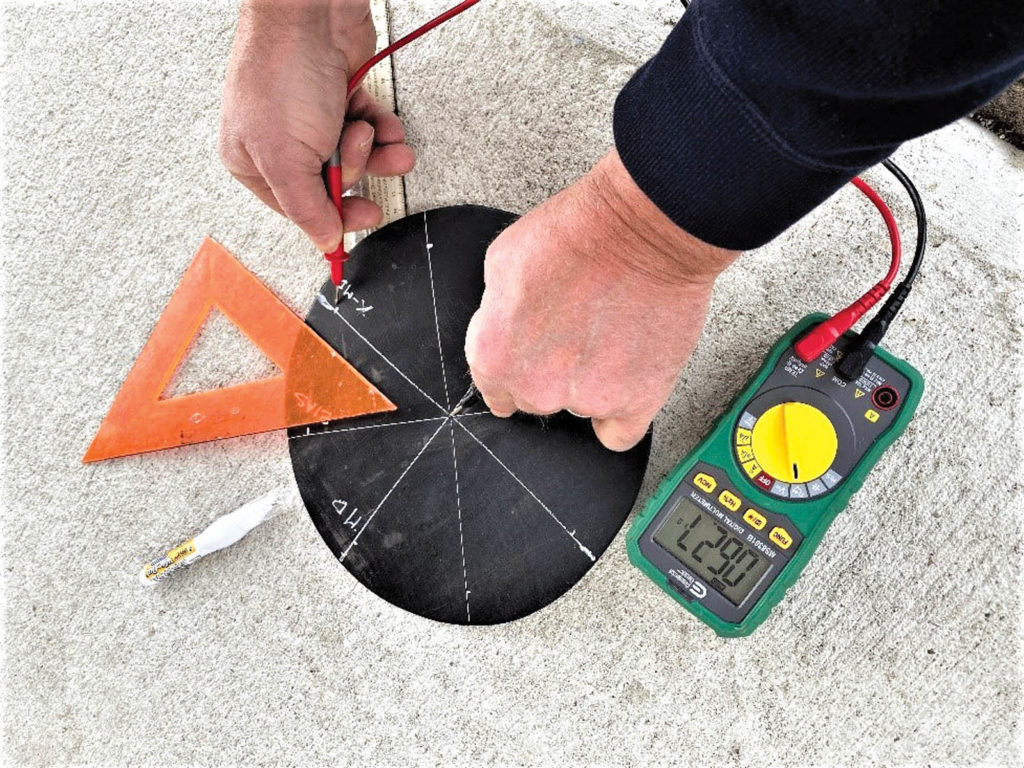
All that is needed for this test is a multimeter, tape measure and protractor. One cuts 10 round specimens from across the roll width of the geosynthetic. The specimens are then conditioned in a lab until they reach a temperature equilibrium of 69.8˚F ± 3.6˚F (21˚C ± 2˚C). The specimens are marked at 4-inch (100-mm) increments in the machine, bias and transverse directions as shown in Figure 1a. The conductive skin is then touched by one free lead near each mark around the perimeter of the circle while the other lead is held fixed at the origin. If a resistance is recorded, the material is conductive, and if no resistance is recorded, then the material is an insulator. For a material to be a good conductor, the electricity passed through it must be able to move the electrons. The more free electrons in a material, the greater its conductivity (Figure 1b).

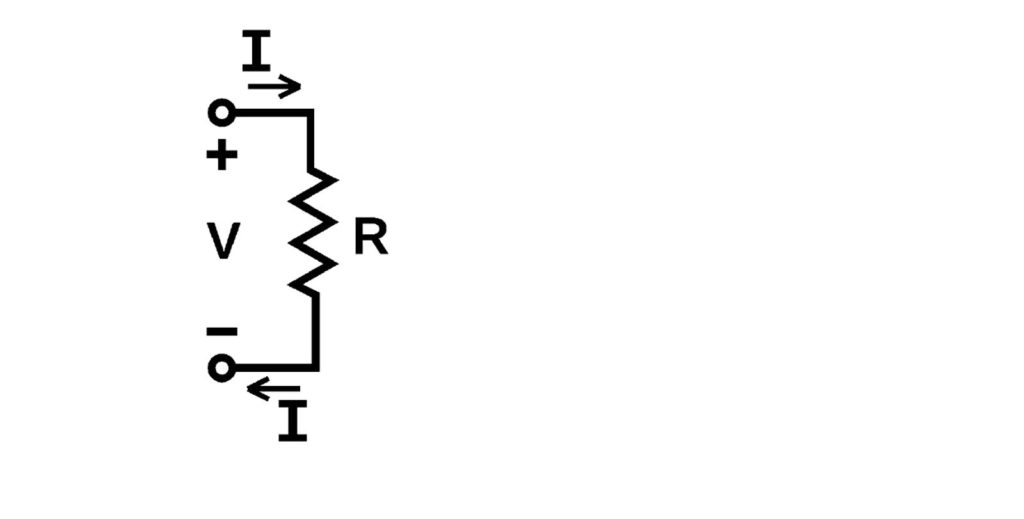
Multimeters measure resistance by injecting a small current into the circuit, and then measuring the voltage drop across those points in the circuit. The known current and the resulting voltage drop are then used to calculate the resistance using Ohm’s Law, which states that the current through a conductor between two points is directly proportional to the voltage across the two points. Introducing the constant of proportionality to the resistance, one arrives at the mathematical Equation 1, which describes this relationship. Please note that the inverse of resistance is conductance.
V=I^2*R
Where:
I=Current through the conductor in units of amperes
V=Voltage measured across the conductor in units of volts
R=Resistance of the conductor in units of ohms
Like most things with electricity, we had to tone down our enthusiasm with this method from its inception in the summer of 2020. At first, we thought we would write a method for conductivity, which is the reciprocal of resistivity. As most of you remember from your first physics class about electricity and magnetism, resistivity is equal to the product of the resistance times the cross-sectional area divided by the length of the conductor, as shown in Equation 2.
ρ=RA/L
Where:
ρ=Resistivity
R=Resistance of the conductor in ohms
A=Cross-sectional area of the conductor
L=Length of the conductor
Unfortunately, our specimen had conductive film of unknown thickness and a multitude of competing circuits wherever the multimeter is engaged with the circular specimen. That is why we decided to simply report resistance over 4-inch (100-mm) increments in multiple directions to assure conductance of the specimen.
Conductive geosynthetics are increasingly being used in critical applications. For years, quality assurance/quality control (QA/QC) professionals have been asking for such a method to assure the material is of proper quality prior to commissioning an ELL survey, as discussed by Thiel, Beck and Smith (2005). We finally have a test that can be included in future specifications when dealing with conductive geosynthetics that will help us on the way to achieving regulatory required allowable/action leakage rates (ALR) of less than 1 gallon per acre per day (10 lphd).
References
Thiel, R., Beck, A., and Smith, M. E. (2005). “The value of geoelectric leak detection services for the mining industry.” Proc., GRI-18 Conf. on Geosynthetics R & D In-Progress, GeoFrontiers 2005, American Society of Civil Engineers, Reston, Va.
 TEXTILES.ORG


