 TEXTILES.ORG

The Reinforced Earth Co. examines the many elements of MSE retaining wall drainage when there are obstructions.
Two common types of obstructions we see behind a retaining wall face are site drainage structures and bridge abutment piles. The presence of—and loading from—these obstructions within the select fill volume of a retaining wall can present challenges for retaining wall designers and installers. However, there are proven measures that can be taken with coordination by the civil engineer, structural engineer, wall designer, and installers to ensure the wall and other elements perform as intended.
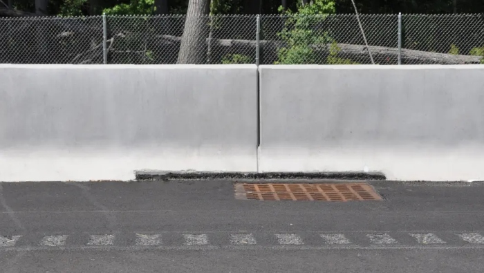
Site drainage
Site drainage obstructions behind retaining walls include drop inlets and reinforced concrete pipes in a variety of sizes, shapes and configurations.
To avoid or reduce the need for modified construction techniques and additional structural material, the most basic recommendation is to move all drainage structures away from the face of the retaining wall wherever possible. In the case of the Reinforced Earth Co.’s MSE walls, locating the drainage structures beyond the free end of the soil reinforcements will fully eliminate the need for modifications of the facing panel connections and skewing of the soil reinforcements.
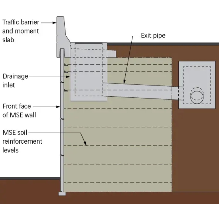
If the drainage inlets must be at the gutter line, it is beneficial to use transverse exit pipes to connect beyond the end of the select backfill zone and to run the longitudinal pipes behind the back of the MSE wall volume. This solution eliminates the longitudinal pipe directly behind the wall face and is especially effective for long walls with long runs of longitudinal drainage pipes.
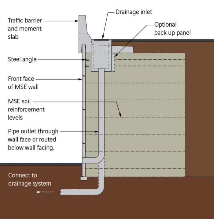
Another solution to avoid longitudinal pipes—common in Texas and Pennsylvania—is to vertically exit the drainage using a pipe through the wall facing or draining below the wall facing to the rest of the drainage system. The following concept also includes a backup panel behind the inlet, which may be recommended for replacing soil reinforcements that would be otherwise blocked by the inlet.

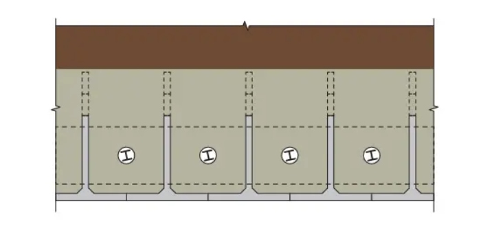
When drainage inlets and pipes must be located within the retaining wall’s fill volume, a typical arrangement behind a Reinforced Earth Co. MSE wall may look like the following:
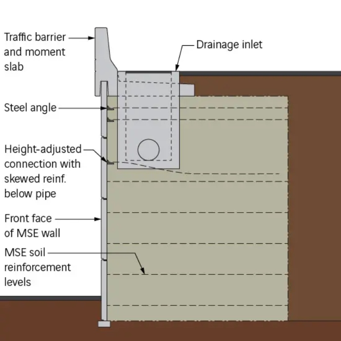
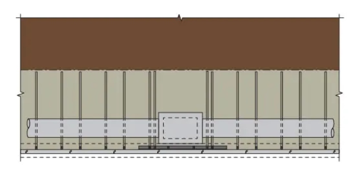
The preceding concept shows a drainage inlet and pipes placed against the roadway gutter line, which is typical in highway construction. In this example, the drop inlet conflicts with multiple levels of soil reinforcements behind one column of panels, and the pipe conflicts with one or two levels of soil reinforcements over its entire length. The most common way for the MSE wall to accommodate this is by using some special design and construction techniques.
Vertical skewing of soil reinforcements
Reinforced Earth Co. soil reinforcements may be gradually skewed or bent up or down to avoid obstructions such as a reinforced concrete pipe running along the back face of the wall. The angle should be kept at a maximum of 15˚. If based on the size of the pipe and proximity to the wall face it is determined that more than 15˚ would be needed, then additional measures must be taken. This can include adjusting the location vertically of the soil reinforcement connections on the facing. The adjustment can be done in the field with additional accessories, but it’s best to predetermine the required locations and place them during casting of the facing panels.
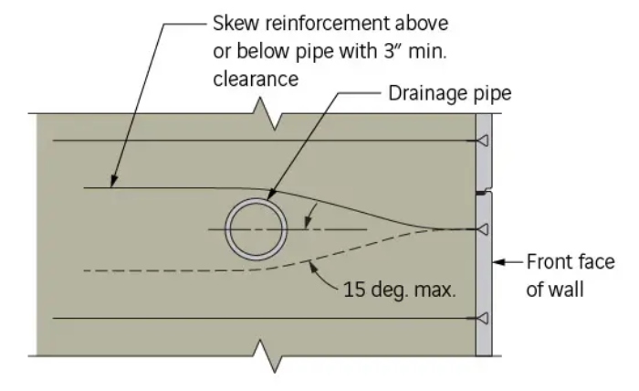
When considering vertical skewing of soil reinforcements, it’s important to note that there is some guidance on the pipe size and location. AASHTO limits the vertical spacing of soil reinforcements to 33 inches (84 cm) maximum. This means that pipes of certain diameters must be a minimum distance from the back face of the wall panels to allow a 15˚ maximum skew angle of the soil reinforcements. In general, it is best to limit the pipe size to 24 inches (61 cm) inside diameter.
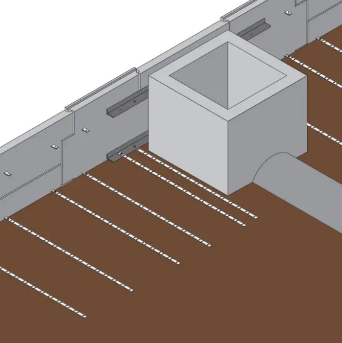
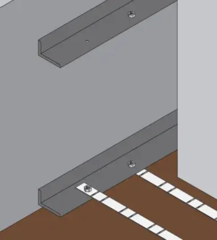
Steel angles for relocating soil reinforcements: Often, entire panels or large sections of panels can be obstructed by an inlet to the point where an inadequate amount of soil reinforcements can be connected to the panel. In this case, the obstructed panel must be mechanically connected to the panels on either side. Typically, a 10 foot (3 m) long steel angle will be used. It is bolted to the embedded panel connections, and then soil reinforcements that are obstructed by the inlet can be moved laterally and bolted to the steel angle.
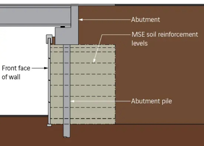
Bridge abutment piles
Bridge abutment deep foundation elements are also common in highway bridge design. They can be in the form of relatively narrow H-piles, or caissons several feet wide. The size, spacing, and loading of the elements will dictate how the associated retaining wall is designed.
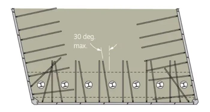
A common configuration for bridge abutment piles behind a MSE retaining wall usually involves one or two rows of piles spaced about five feet apart. In this case, the retaining wall’s soil reinforcements are easily skewed away from perpendicular to accommodate the piles. Normally, a 15˚ skew is acceptable without consideration in the design calculations. Additional skew angle of 30˚ can be allowed by adding the criteria to the internal stability calculations.
To minimize any special design to the retaining wall, an 18-inch (46-cm) clearance from the back face of the retaining wall is ideal. It will also facilitate proper compaction between the piles and wall face when placing backfill.
If relatively large elements or a dense pile group must be used behind a MSE wall, the wall designer can apply one or more methods to the design to alleviate any constructability issues and conflicts with the soil reinforcements:
- Providing additional soil reinforcement connection points on the facing panels. With guidance from the wall designer, this can provide the installer with a choice of connection points based on the location of the piles to minimize horizontal skewing.
- Ten foot (3 m) wide facing panels, instead of 5 foot (1.5 m) wide.
- In cases of extreme loading, the inclusion of intermediate rows of soil reinforcement.
Reinforced soil: A practical limit
There is a practical limit to the size of obstructions within the reinforced volume of an MSE retaining wall, which is reinforced soil. If there is too large of an obstruction, there is no more soil to reinforce. When obstructions are very large, alternate retaining wall solutions may be required.
Other wall types
T-Wall
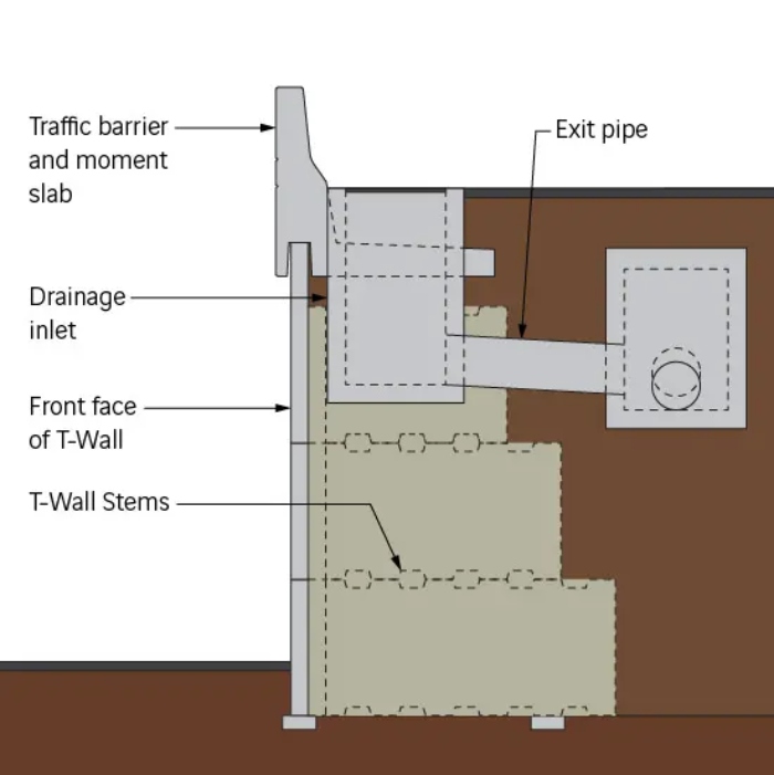
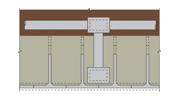
T-Wall is more restrictive to drainage and pile location because the concrete stems cannot be altered in the field. It is best to keep drainage structures behind the end of the T-Wall stems. If the drainage structures must be directly behind the wall face, their locations should be coordinated with the wall designer to ensure that they are placed between the T-Wall stems, which are typically spaced between 5 feet (1.5 m) and 7.5 feet (2.3 m). Longitudinal pipes cannot be placed directly behind the wall face, as the T-Wall stems will conflict. A transverse exit pipe would be required.
Similarly with abutment piles, the T-Wall system must be coordinated with the bridge designer to ensure that the piles are located in between the T-Wall stems.
TechWall
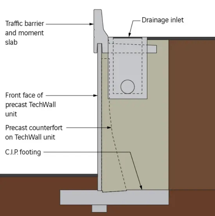
Of the Reinforced Earth Co.’s retaining wall alternatives, TechWall can require the least effort to accommodate drainage structures. The wall facing is relatively thin, similar to an MSE wall, and there are no soil reinforcements. The counterforts generally do not extend far back enough into the select backfill to affect the common placement of drainage pipes.
If TechWall is used at a bridge abutment with piles, the piles will need to protrude through the cast-in-place footing of the wall. Coordination between the wall designer and the bridge engineer would be necessary. The wall designer will accommodate the geometric configuration of the piles and any loading imposed from the piles to the wall footing.
Other special conditions
In addition to the common methods described herein, every project is different and can require a variety of other special solutions to accommodate obstructions within a retaining wall’s fill. Types of obstructions can go beyond the typical drainage inlet, abutment pile or guiderail post.
In addition, expected consolidation or differential settlement of a retaining wall in fill can influence the methods and sequence that drainage and other items must be installed within the backfill.
It’s important that each member of the project team coordinates with each other during the design, so that the installation goes smoothly and all structures involved perform as intended.
Some guidance is provided in AASHTO Section 11.10.10.4 Obstructions in the MSE Wall Backfill.
This article first appeared on the Reinforced Earth Co.’s blog.