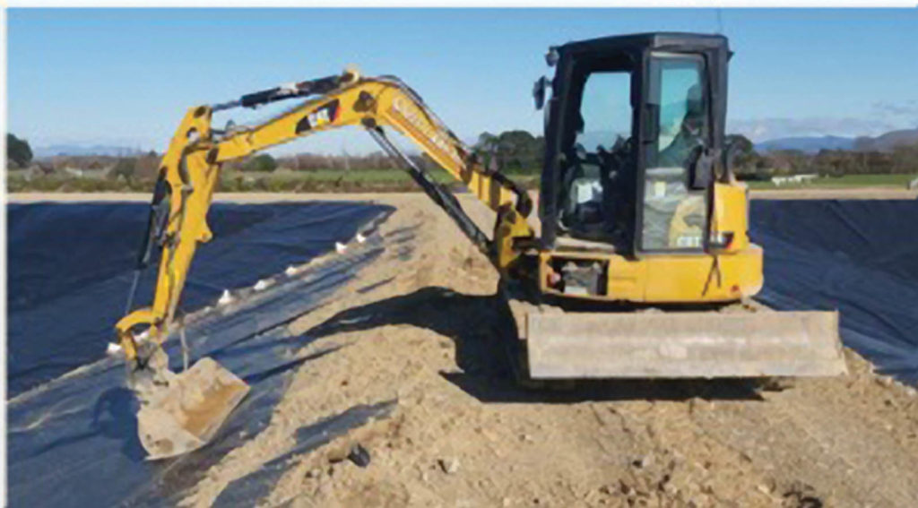
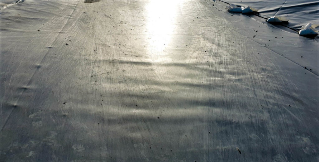
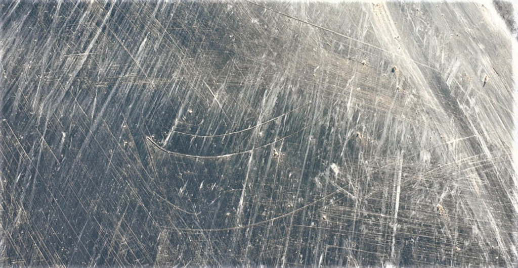
Q: I have a project where multiple and extensive scratches were created on the high-density polyethylene (HDPE) liner for a reservoir due to poor construction practices. (See the following Figures 2–4.)


Despite repeated reminders, the main earthwork contractor’s activities on-site had created extensive surface damages to the 60-mil (1.5-mm) HDPE liner (conductive liner with 1,000 hours stress crack resistance) that was installed for the reservoir. The scratches are generally located at the crest of the reservoir and at the toe, with some along the full panels.
We are trying to establish the level of repairs required. It is difficult to estimate what needs to be repaired and how depending on the severity and extent of the scratches.
Would you be able and willing to express an opinion regarding the impact of scratches on HDPE liners? What is the effect on strength and long-term durability, and what level of defects should warrant a repair/replacement?
We have obtained samples and sent to a lab for measurement—noting that measurement of scratch depth is not easy. We also purchased a laser micrometer to measure the scratch depths on-site, work that is ongoing.
A: The question of the impact of scratches on HDPE liners due to poor construction practices and lack of construction quality assurance (CQA) has been asked many times. I am troubled to hear that the surface damages are on a smooth 60-mil (1.5-mm) HDPE conductive liner. You are correct that the task of the engineer now is to assess the severity and extent of the scratches and how they will affect facility performance (strength, diffusion, conductivity, long-term durability, etc.) going forward.
The first task is to set boundary conditions on what is a “significant” scratch. One is trying to distinguish between a blemish and a defect. Note that thickness control for smooth 60-mil (1.5-mm) HDPE conductive liner made on a blown film line is typically 4 to 6 mil (0.1 to 0.15 mm). The lower limit is set as the mean thickness variability, which is a little over 6% of the thickness and the upper limit is set at 10% of the nominal thickness. Your case is tricky because the conductive layer (which might be on top) is only 5.2 mil (0.13 mm) thick. It is imperative to set these limits at the beginning of the project.
The next task is to obtain samples and see if the scratches are significant. We have found that the best way to do this is optically via microtome specimen cut orthogonally to the scratch through the geomembrane cross section.
The third task is to show the effect your scratches have on facility performance long term. This is very difficult. Note that the weathering of any polymer is materially and environmentally specific. It involves considerable laboratory testing and many paramedic design calculations to answer this question specific to your application. In addition, stress will impact the results. Furthermore, stresses will be the greatest at the crest of the slope, where it appears the geomembrane is being scratched. That said, 3D axisymmetric tests per ASTM D5617 work well to differentiate blemish versus defect in the short term.
Finally, you need to determine whether to repair or replace the areas that have been scratched. Please note, I have seen repairs done on more significant scratches. Grinding in advance of fillet extrusion welding is not without its consequences, and this repair needs to be done correctly by a skilled installer. If the scratches are determined to be defects rather than blemishes, I would consider replacement.
 TEXTILES.ORG


