 TEXTILES.ORG

By Stephan Fourmont, Pascal Saunier and Toraj Ghofrani
Landfill gas (LFG) is produced during the decomposition of putrescible material in landfills. Often referred to as biogas, LFG is a source of odors and fugitive greenhouse gas (GHG) emissions. LFG is typically 40%–60% methane, which is 25 times more potent to affect climate change than carbon dioxide (U.S. Environmental Protection Agency 2013). LFG must be removed from the landfill to reduce or eliminate odors, to limit the migration of methane to the atmosphere and to comply with regulatory requirements.
The management of LFG at landfills is an important, and often costly, operational aspect of a well-run landfill. The need to install a gas collection and control system (GCCS) is dependent on the amount and type of waste accepted. Typically, LFG is controlled by an active vacuum blower system, which extracts LFG through a network of horizontal collectors embedded in rock-filled trenches inside the waste. The collected LFG is typically sent to a destruction device, such as a flare, where it is combusted, and the methane is converted to carbon dioxide. Because of the energy potential of the methane gas, landfill gas-to-energy (LFGTE) projects have been developed to capitalize on renewable sources of green fuel. In general, LFGTE projects use the LFG to fuel specially designed turbines, reciprocating engines or boilers. LFGTE projects can have design lives in excess of 20 years and range in size from a few kilowatts to 10 megawatts or more. Also, LFG can be processed into a compressed or natural gas for home heating or vehicle use, respectively.
The success of an LFGTE project is directly related to the performance of the GCCS. Traditional methods of LFG collection can be time-consuming and expensive to install, and installation sometimes can be delayed due to seasonal and budgetary issues. This paper presents the significant advantages of using a tubular drainage geocomposite for LFG collection as compared with traditional horizontal LFG collectors (Figure 1).

Minitube blanket description and installation
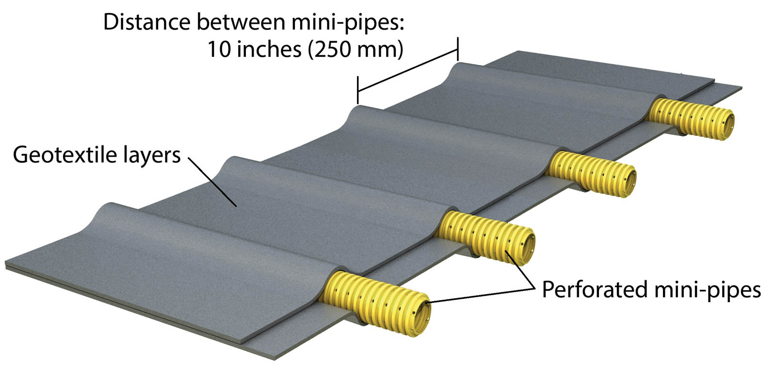
As this technology differs from more common solutions, it is important to first describe the product to be used. The minitube blanket is comprised of 1-inch (25-mm) corrugated polypropylene perforated pipes spaced on 10-inch (250-mm) centers between two nonwoven geotextile layers (Figure 2).
Tubular drainage geocomposites have been used in landfill applications around the world for more than 25 years. They are compliant with ASTM D7931, Standard Guide for Specifying Drainage Geocomposites, and are defined as multilinear drainage geocomposites in ASTM D4439, Standard Terminology for Geosynthetics.
An important characteristic of tubular drainage geocomposites is that they maintain their transmissivity under significant normal stresses (Saunier et al. 2010) because they don’t experience geotextile intrusion into the drainage conduits (the minitubes) and no creep in compression of the minitubes when confined. Therefore, for most applications, the applied combined reduction factors for tubular drainage geocomposites are almost half of those applied to standard geonet geocomposites (Maier and Fourmont 2013).
A roll is typically 13-feet (4-m) wide and it replaces a 3-foot (0.9-m) wide × 6.5-foot (2-m) deep trench filled with aggregates surrounding a 6-inch (150-mm) diameter perforated high-density polyethylene (HDPE) pipe. Common spacing between horizontal LFG collectors is about 50–100 feet (15–30 m) horizontally and 30–40 feet (9–12 m) vertically. This is a significant loss of airspace and waste disposal tipping fees during the lifetime of a landfill.
The minitube blanket is unrolled directly on the waste and connected to a collector pipe using connectors specially developed to fasten the pipes from the composite to the collector pipe (Figure 3). Due to its limited thickness and its low hydraulic conductivity in contrast with the surrounding waste, the minitube blanket network won’t obstruct the downward leachate flow into the waste mass and reduce the potential for plugging the perforated LFG collectors. Nevertheless, some specific measures will be taken to manage the condensates (gradation of the support with a slope away from the manifold, condensate drain at one end of the manifold, etc.).

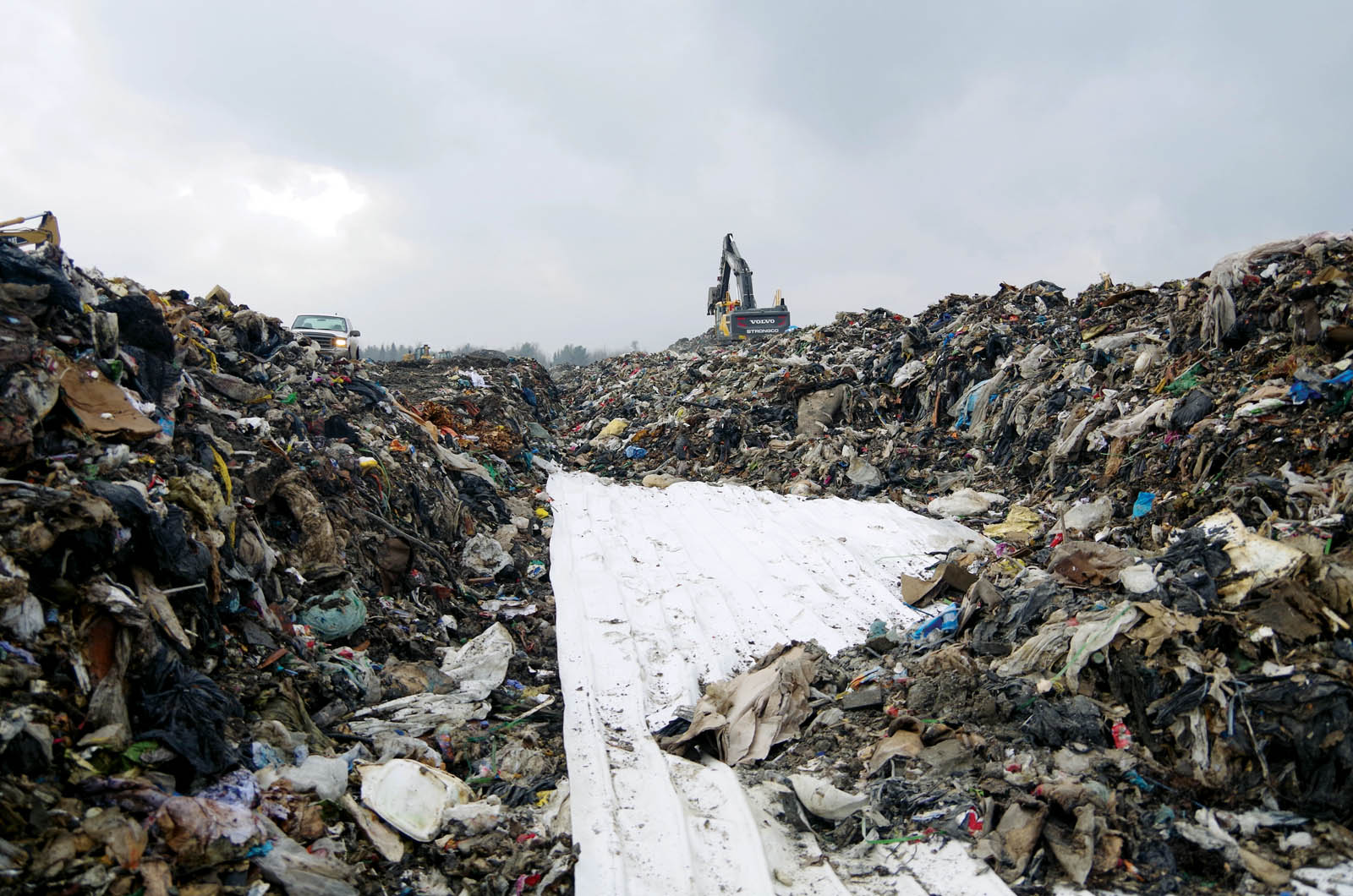
Waste is placed directly over the minitube blanket (Figure 4). A minimum of 3 feet (0.9 m) of selected waste should be placed on top of the geocomposite prior to operating a compactor over the area. The size and weight of the waste compactor, as well as the length of the compactor teeth, should be considered when designing the thickness of the initial waste layer over the geocomposite.
In-place behavior
For horizontal LFG collection, the flow and the head loss in the minitube blanket are governed by the minitubes (the head loss in the geotextile layers being negligible). In a first stage, the low-pressure Muller equation can then be used because the pipes of the geocomposite follow the same physical laws as a conveyance pipe for gas collection (Steinhauser and Fourmont 2015).
The gas flow of the minitube is given from its water flow using Equation 1 (Faure and Auvin 1995):

With:
Q: flow drained by the minitube (Qw: water flow, Qg: gas flow)
qp: discharge capacity of the minitube [(qp)w for water, (qp)g for gas]
i: hydraulic gradient (iw for water, ig for air)
α, n: constants
ρ: density (ρw for water, ρg for gas)
Compared to water, this ratio is about 28 for air, 22 for CO2 and 37 for CH4.
From Faure and Matichard (1993), the maximum waterhead in the minitube function of the collected flow per unit area is given by Equation 2:
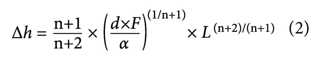
With:
Δh: waterhead (water column)
d: distance between the minitubes
F: flow of liquid collected per unit area
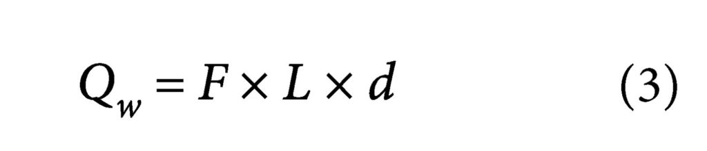
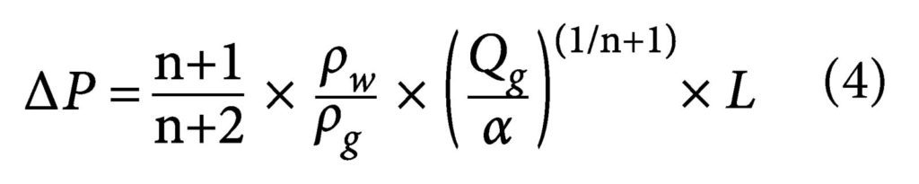
The flow drained by the minitube blanket is also given by Equation 3:
Then, using Equation 1 and Equation 3 in Equation 2, the head loss in the minitube is given by Equation 4:
Lymphea software combines these equations to determine the flow of gas collected by the geocomposite as a function of the horizontal LFG collector length and the applied vacuum. This software has been developed by the Laboratoire Interdisciplinaire de Recherche Impliquant la Géologie et la Mécanique (LIRIGM) from the University of Grenoble, France, and validated by large-scale tests. It can be obtained from the manufacturer.
Comparison to a traditional trench
The performance of a minitube blanket and a traditional horizontal LFG collector were tested side by side in the same 800-foot (245-m) refuse trench at Cedar Hills Regional Landfill, located in Maple Valley, Wash. (Ghofrani 2016). The traditional LFG collector was comprised of a 6-inch (150-mm) HDPE pipe with six 0.5-inch (13-mm) perforations, 60° apart and 6 inches (150 mm) on center. The geocomposite was comprised of 1-inch (25-mm) diameter corrugated polypropylene perforated minitubes needlepunched between two nonwoven geotextile fabrics. The tested geocomposite was 3-feet (0.9-m) wide with four minitubes.
The performance of a minitube blanket and of a traditional LFG collector were evaluated based on monitoring of the vacuum zone of influence, landfill gas flow rate, methane (CH4), oxygen (O2), nitrogen (N2) and carbon dioxide (CO2) data, using a GM 5000 field instrument. The vacuum measurements were made using a Magnehelic gauge at 50-foot (15-m) intervals along the length of the trench.
As presented in Figure 5, the vacuum along the trench decreased from 4.5–2.9 inches (114 to 74 mm) of water column (WC) in the traditional LFG collector as compared to 1.5–0.88 inches (38 to 22 mm) of WC in the minitube blanket. Therefore, a vacuum loss was higher in the traditional LFG collector as compared with the minitube blanket (65% versus 58%), indicating a better distribution of vacuum along the trench by the minitube. Moreover, due to numerous redundancies of corrugated polypropylene perforated pipes 10 inches (254 mm) apart, the minitube blanket offers a more reliable radius of influence to collect LFG than traditional LFG collectors 50–100 feet (15–30 m) apart.

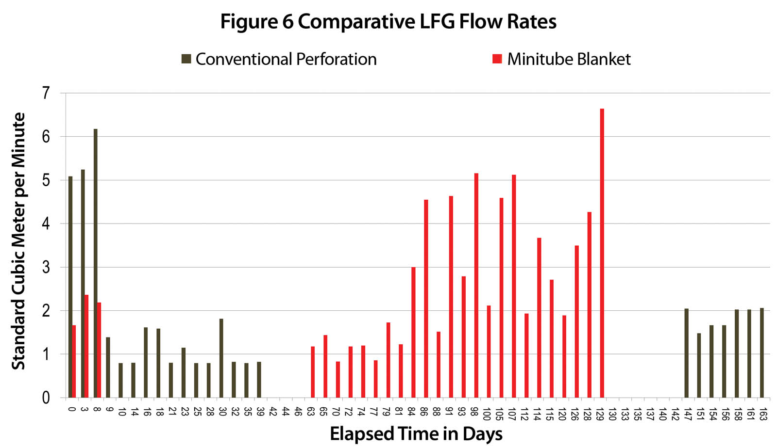
Furthermore, even though the traditional LFG collector had higher vacuum availability, the minitube blanket provided equal if not better flow rates. As presented in Figure 6, the average LFG flow rate for the traditional collector was 67 standard cubic feet per minute (2 standard m3/min), while the average LFG flow rate for the minitube blanket was 97 standard cubic feet per minute (3 standard m3/min) under the same condition and during the same testing period.
The minitube blanket performance was equally compatible with the traditional LFG collector with respect to fixed gases:
The CH4 concentrations ranged from 25%–58% for the traditional LFG collector and 33%–63% for the minitube blanket LFG collector.
The O2 concentrations ranged from 0.3%–1.3% and 0.0%–3.5%, while the N2 concentrations ranged from 0.0%–46% and 0.0%–37% for the traditional LFG collector and minitube blanket, respectively.
The CO2 concentrations were similar for both the traditional LFG collector and the minitube blanket, ranging from 26%–30% and 26%–41%, respectively.
The rate at which microbes generate LFG can be best described as a slow diffusive process rather than a fast advective process. If an LFG collection system is designed with excessive vacuum pull/flow rates, excessive air intrusion may occur.
With almost half of the perforation area of the traditional LFG collector, the minitube blanket performance is similar if not better that the traditional LFG collector. Additionally, the geocomposite offers savings in airspace utilization due to its compact geometry. The corrugated polypropylene also offers more resiliency toward long-term landfill settlement.
Greenhouse gas emissions
The use of the minitube blanket in replacement of granular material permits the reduction of GHG emissions up to 87% equivalent CO2e with matching hydraulic performances (Durkheim and Fourmont 2010).
In the specific case of horizontal LFG collection, Table 1 presents the CO2e emissions per linear meter for the minitube blanket considering a distance from the manufacturer to the landfill site of 1,240 miles (2,000 km).

In comparison, the calculation of CO2 emissions per linear meter for a 3-foot (0.9-m) wide × 6.5-foot (2-m) deep trench filled with aggregates surrounding a 6-inch (150-mm) diameter perforated HDPE pipe is presented in Table 2.

The calculations were carried out using the carbon footprint method developed by the Agence de l’Environnement et de la Maîtrise de l’Énergie (ADEME). The use of the minitube blanket offers a considerable reduction of CO2e emissions of 77% for the same or better performance. It represents a savings greater than 18 kg CO2e per linear foot (more than 60 kg CO2e per linear m) of horizontal LFG collector.
Conclusion
LFG collection has never been of greater concern than now in the waste management industry. Being able to efficiently collect landfill gas will help landfill owners-operators and municipalities increase their revenue by recycling methane and will reduce the negative impacts to the environment, like odors and fugitive GHG emissions. Trenches, gravel, pipes and geotextiles were used for decades to maximize the LFG collection efficiency. Solutions now exist to largely improve the management of LFG and convert it to renewable energy, as a natural and free resource.
One of the better emerging solutions is the minitube blanket technology, which offers a more flexible solution with an enhanced control over LFG collection, containment and conveyance, as well as a reliable vacuum radius of influence and comforting redundancy while drastically reducing construction costs, odor and fugitive GHG emissions. Lastly, one of the greatest advantages of the minitube blanket over a traditional LFG collector is saving landfill airspace for its intended refuse disposal and its corresponding revenue from tipping fees.
References
ASTM D4439, Standard Terminology for Geosynthetics, ASTM International, West Conshohocken, Pa., 2018, www.astm.org.
ASTM D7931, Standard Guide for Specifying Drainage Geocomposites, ASTM International, West Conshohocken, Pa., 2018, www.astm.org.
Durkheim, Y., and Fourmont, S. (2010). “Drainage geocomposites: A considerable potential for the reduction of greenhouse gas emission.” Proc., 9th Int. Conf. on Geosynthetics, Guaruja, Brazil.
Faure, Y. H., and Matichard, Y. (1993). “Experimental and theoretical methodology to validate new geocomposite structure for drainage.” Geotextiles and Geomembranes, 12, 397–412.
Faure, Y. H., and Auvin, G. (1995). “Gas drainage by geocomposites.” Rencontres 95 du CFG, 63–69.
Ghofrani, T. (2016). “Comparative studies of three different horizontal landfill gas collector designs.” Cedar Hills Regional Landfill, Maple Valley, Wash.
Maier, T. B., and Fourmont, S. (2013). “How tubular drainage geocomposite was used in landfill final cover.” Geosynthetics, 31(3), 48–51.
Saunier, P., Ragen, W., and Blond, E. (2010). “Assessment of the resistance of Draintube drainage geocomposites to high compressive loads.” Proc., 9th Int. Conf. on Geosynthetics, Guaruja, Brazil, Vol. 3, 1131.
Steinhauser, E., and Fourmont, S. (2015). “Innovative approach to landfill gas collection and control.” Proc., Geosynthetics Conf., Portland, Ore., 283–290.
U.S. Environmental Protection Agency. (2013). 40 CFR Part 98–2013, Revisions to the Greenhouse Gas Reporting Rule and Final Confidentiality Determinations for New or Substantially Revised Data Elements; Final Rule, Federal Register, 78(230).
Stephan Fourmont is business development manager–east with AFITEX-Texel Geosynthetics Inc. in Montreal, Que., Canada.
Pascal Saunier is business development manager–North America with AFITEX-Texel Geosynthetics Inc. in Vancouver, B.C., Canada.
Toraj Ghofrani is engineer III with the King County Solid Waste Division in Maple Valley, Wash.
All photographs courtesy of AFITEX-Texel Geosynthetics Inc.