 TEXTILES.ORG

By Sachin Mandavkar and Mehari Weldu
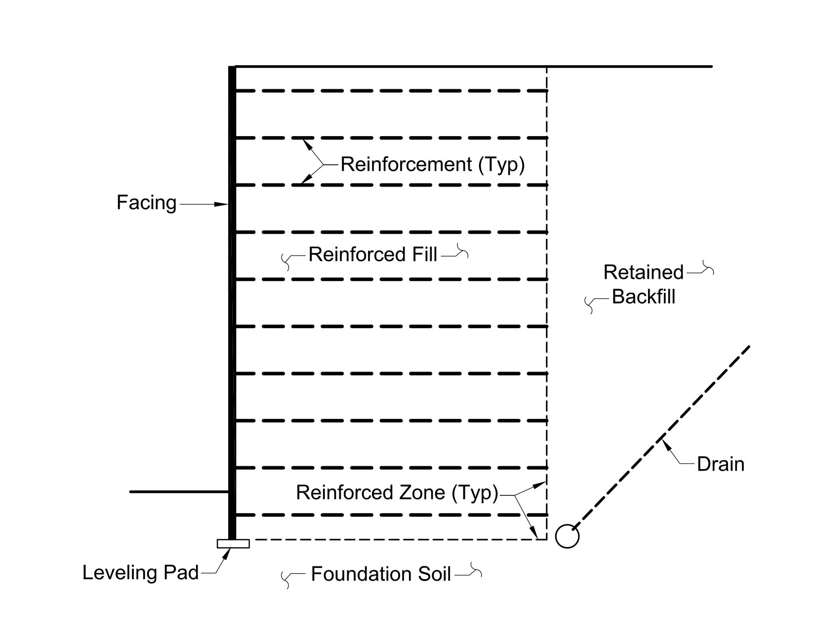
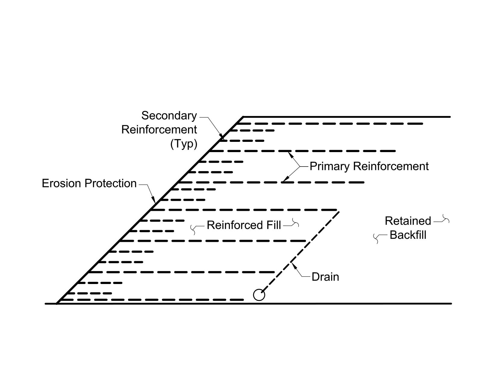
Reinforced soil structures are geotechnical systems consisting of reinforcing elements and primarily include mechanically stabilized earth (MSE) walls and reinforced soil slopes (RSS) (Figure 1). MSE walls and RSS are constructed by placing alternating layers of reinforcement and compacted soil behind a facing element to form a composite material that acts integrally to restrain lateral forces. In ancient times, a variety of materials were used as soil-reinforcing elements, including tree branches and straw. Common types of modern soil-reinforcing elements are steel strips, welded steel grids, wire mesh, geogrids and geotextile sheets. The use of a facing system prevents soil raveling between the reinforcing elements and allows very steep slopes and vertical walls to be constructed safely. A wide range of materials are used as facing, including precast concrete panels, dry cast modular blocks, welded wire mesh, wraparound geosynthetics and gabions. The soil material placed within the reinforcement zone is referred to as reinforced fill, and the in situ soil or backfill material placed directly behind the reinforced zone is termed as a retained backfill. Figures 2 and 3 show the main components of a generic MSE wall and RSS system, respectively.
The use of MSE walls and RSS have progressively grown over the last four decades due to advantages they provide compared to alternative soil-retaining structural systems. The cost-effectiveness and simplicity of the construction technique, speed of construction and flexibility of reinforced soil structures are among the benefits that make the technology popular and very attractive. As described above, MSE walls and RSS can be reinforced using metallic and geosynthetic-reinforcement materials. This paper, however, focuses on geosynthetic-, particularly geogrid-, reinforced structures and does not address other reinforcement types.
Geosynthetic materials have been developed and used as reinforcement in soil-retaining structures since the early 1970s. The first geotextile-reinforced wall was constructed in France in 1971, and the first structure of this type in the United States was constructed in 1974. Geogrids for soil reinforcement were developed around 1980. The first use of a geogrid in soil reinforcement was in 1981, and extensive use of geogrid products in the United States began in about 1983. Since the early 1980s, the use of geosynthetics in reinforced soil structures has increased significantly, and they now comprise a growing portion of the reinforced soil market. Technological developments in the polymer industry have been continuously incorporated into new geosynthetic products, enhancing geosynthetic material properties used in geotechnical applications. Advancement of geosynthetic materials as reinforcement for reinforced soil structures is still progressing, and improvements are being made in the way MSE walls and RSS are designed and constructed. To date, thousands of geosynthetic-reinforced soil structures have been designed and successfully constructed for highways and other applications, which include MSE wall and RSS systems. A large portion of these structures were designed with geogrid products as a reinforcement element.
Design methodology and considerations
The design of MSE walls and RSS relies more heavily on the input of the geotechnical engineer than for traditional wall systems and unreinforced embankments. The design steps are also more extensive, and the design of soil-reinforced structures requires a shared design responsibility between material suppliers and owners or the owners’ engineer. Traditionally, all civil engineering features in North America were designed using the allowable stress design (ASD) platform methodology. More recently (1994 in the U.S.), a load and resistance factor design (LRFD) methodology has been implemented in highway structure design practices such as MSE walls. The LRFD method in various forms is now being applied throughout the world. For example, Eurocode uses the limit state design (LSD) methodology, which is very similar to the LRFD methodology. The LRFD methodology has not developed yet for engineered embankments and RSS. A limit equilibrium, ASD approach is still used for RSS and the factor of safety must be adequate for both the short- and long-term conditions for all possible modes of failure. Regardless of the design platform methodology, the core analytical methods for soil-reinforced structures, such as external and internal stability evaluation, remain unchanged. The primary change is in the way the loads and resistances are compared and how uncertainty is incorporated in the design process. Computer programs such as MSEW and ReSSA, developed by ADAMA Engineering Inc., are among the most commonly used software for design of MSE walls and RSS, respectively.
The internal stability of geosynthetic-reinforced soil structures is mainly governed by the geosynthetic behavior and its interaction with the reinforced fill material. Soil-geosynthetic interaction is influenced by the engineering properties of reinforced fill material. Although, theoretically, reinforced fill can be composed of a wide range of soil types, granular soils are recommended by the American Association of State Highway and Transportation Officials (AASHTO) as select fill material for MSE walls because of their high strength, stiffness and permeability. In the case of RSS, reinforced fill with up to 50% passing a No. 200 (0.75 mm) sieve is recommended by the Federal Highway Administration (FHWA). Where select granular soils are not readily available, the use of cohesive materials may be desirable to improve the cost-effectiveness of the system, but cohesive soil presents a more complex material behavior, and its use is not an industry standard practice.
The impact of geosynthetic characteristics on the long-term performance of MSE walls and RSS should be carefully considered during the design process. In designing geogrid-reinforced soil structures, the design engineer should carefully consider geogrid mechanical, creep, installation damage and durability properties, as the long-term strength is directly derived from these properties. Among several mechanical properties, the geogrid ultimate tensile strength is the most relevant property for the design of MSE walls and RSS. Geogrid installation damage is a function of geogrid type and the reinforced fill gradation. For tall reinforced soil structures, where higher stress levels are imposed to the geogrids, creep behavior can be critical in successful performance of the structure. In general, the most significant durability properties are related to thermochemical degradation, such as oxidation, hydrolysis and exposure to ultraviolet (UV) rays. These effects should be considered in design based on the geogrid type and project design conditions. Generally, tall reinforced soil structures require high tensile strength uniaxial geogrids with good degradation resistance and lower long-term deformation.
For years, geosynthetic-reinforced soil structures have been regularly designed to reach limited heights due to design uncertainties, which primarily are related to the geosynthetics’ properties and their interaction with soil. In the past decade, the advancement in geosynthetic technology and a better understanding of reinforced soil structures behavior has enabled design engineers to use geosynthetics, particularly geogrids, as re-inforcement for MSE walls and RSS to reach new heights.
Case histories
The following highway infrastructure project case histories will present the lessons learned and illustrate that the use of geogrid reinforcement is a feasible and economical solution for tall reinforced soil structures if proper design considerations and materials are selected in addition to quality construction methods.
Cortez Hills Mine crusher MSE wall
A new primary crusher unit was being added to the Cortez Hills Mine in Crescent Valley, Nev. The terrain at the optimum location for the new crusher was extremely challenging. The crusher building houses the primary crusher supported on a 45- × 60-foot (14- × 18-m) reinforced concrete mat foundation with a maximum real load of 11,000 pounds per square foot (53,707 kg/m2). The grade transition between the upper and lower pads on each side of the primary crusher structure was designed using MSE crusher walls, which extend 60 to 80 feet (18 to 24 m) from either side of the crusher structure to steep fill slopes.
The geotechnical investigation consisted of the excavation of eight test pits to depths of 3 to 18 feet (1 to 5.5 m), drilling of one boring to a depth of 100 feet (30.5 m) and the performance of five seismic surveys. Subsurface conditions at the explorations were generally consistent and are made up of predominantly well-graded gravels and cobbles extending to limestone and siltstone bedrock at depths ranging from 1.5 to more than 18 feet (0.5 to 5.5 m). Groundwater was not encountered to the maximum depth explored of 100 feet (30.5 m). A maximum earthquake acceleration of 0.45 g is recommended for design of critical facilities at the Cortez Hills site. The MSE wing walls were designed using the operating basis earthquake (OBE) for the lower-level event. The OBE acceleration of 0.18 g is approximately one-third larger than the maximum historical site acceleration and slightly larger than the U.S. Geological Survey estimate of the 475-year acceleration.
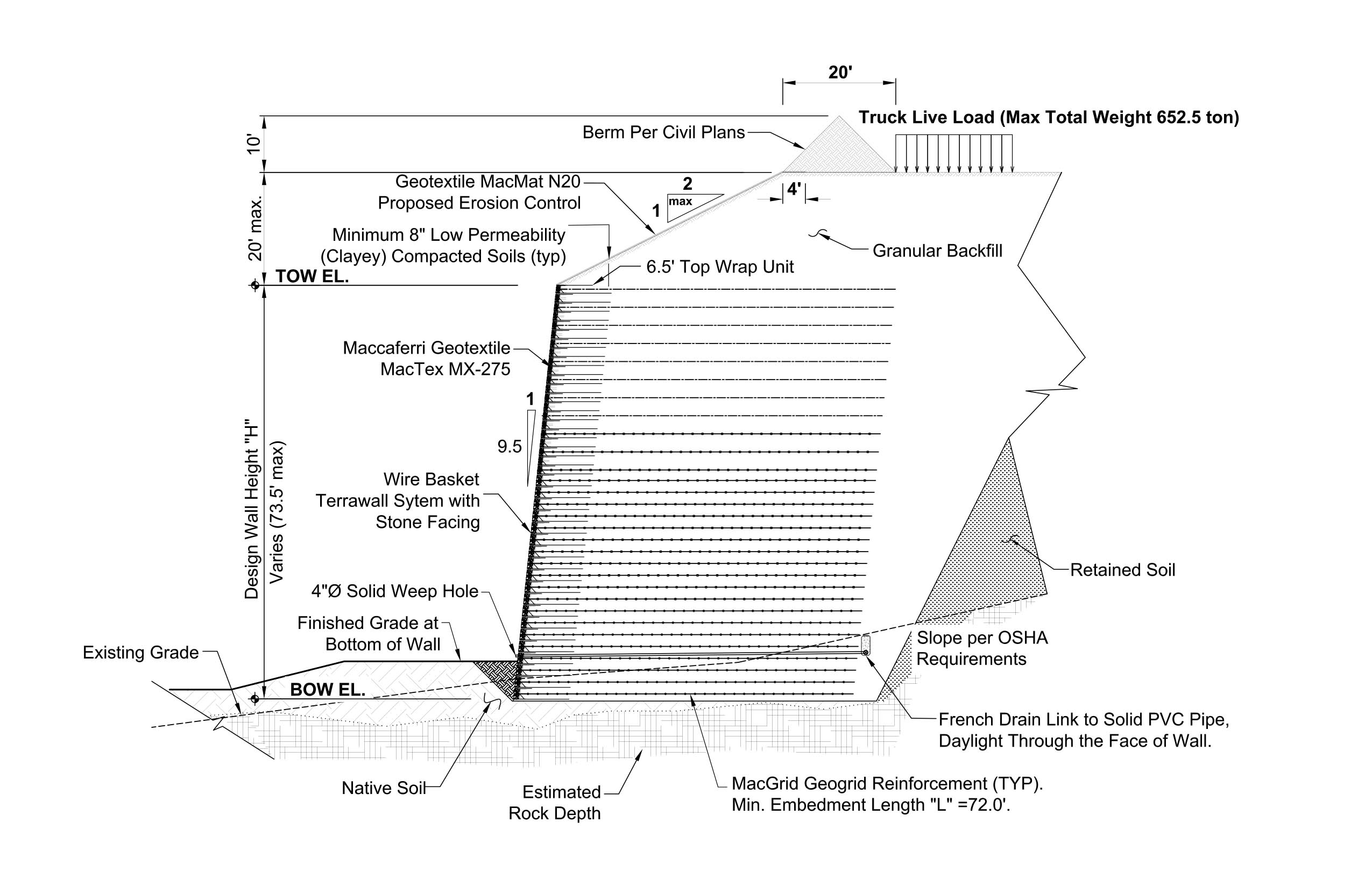
The wire-faced MSE walls were designed to create a safe area for unloading mine trucks and provide stabilized access to the crusher. At its highest section, the MSE wall is approximately 95 feet (29 m) tall, including 2H:1V slope on the top, as shown in Figure 4.
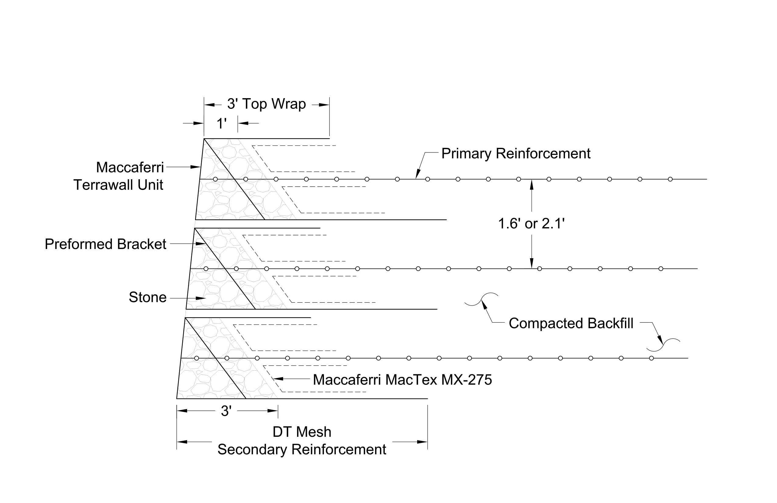
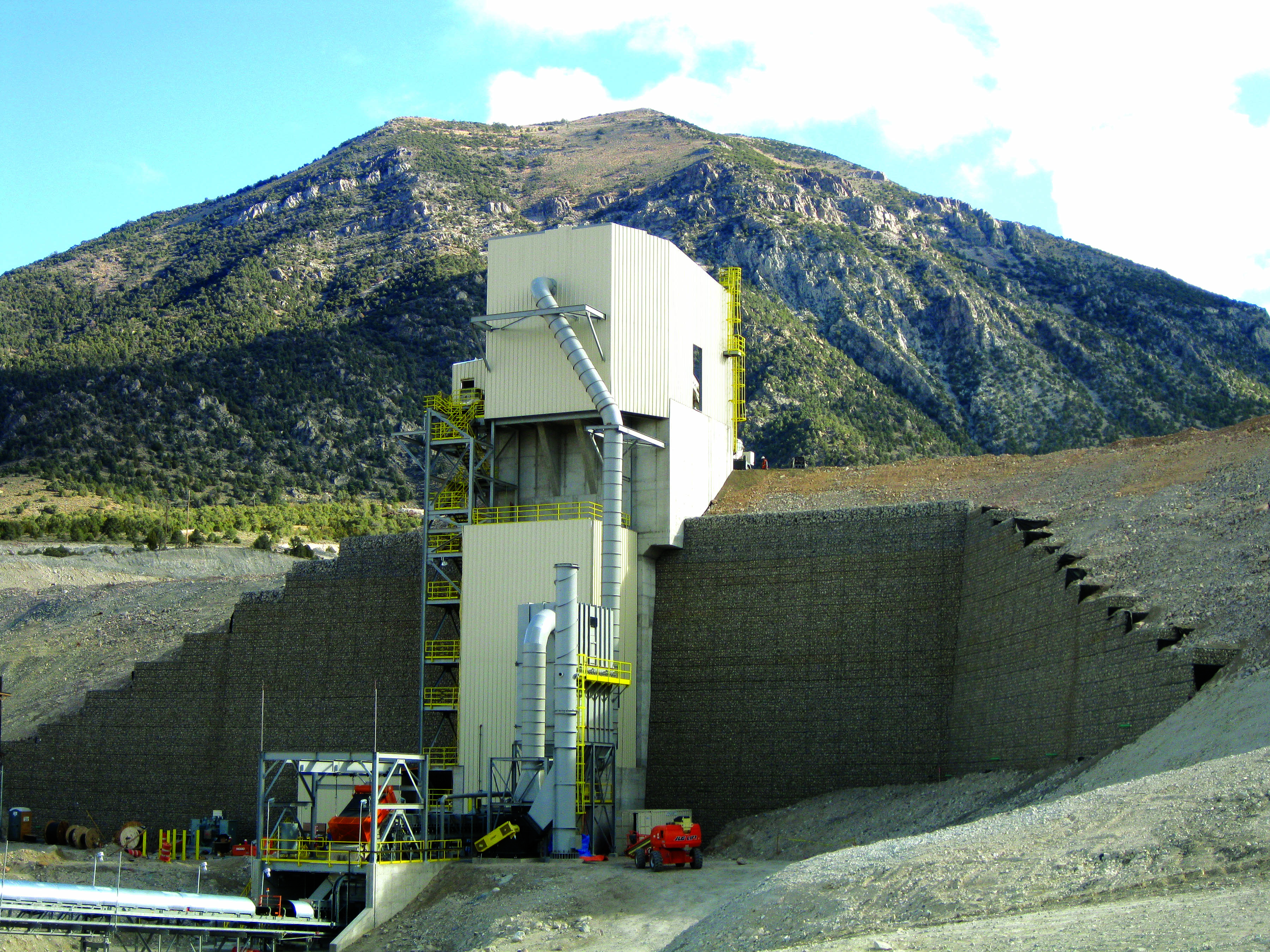
The MSE walls were constructed with multiple layers of primary reinforcement using three different types of uniaxial polyester geogrids to optimize the overall cost of the system. The geogrids were installed at the mid-height of the MSE wall fascia units. The double-twisted wire mesh from the fascia units were extended 9 feet (2.7 m) into the reinforced fill as secondary reinforcements. The MSE wing walls were designed to support the live load of Liebherr T282 B mine trucks, which can generate a loaded weight of approximately 653 tons (592 tonnes) and withstand the vibratory loading during the crushing operation. Proper selection, placement and compaction of the fills were required to reduce the potential for excessive settlement of the pads, to reduce the lateral pressures on the crusher structure and to obtain proper performance of the MSE wall-reinforcement system. Select structural fill material was used as reinforced fill behind the crusher, around buried utilities, for the MSE wall, as leveling fill beneath foundations and to surface the pads. Figures 5 and 6 show the MSE wall system facing detail and postconstruction, respectively.
PROJECT HIGHLIGHTS
Cortez Hill mine crusher MSE wall
Owner: Barrick Gold Inc.
Location: Crescent Valley, Nev.
General Contractor: Ames Constructions
Design Engineer: Terracon Consultants Inc.
Fascia System: Terrawall units (woven wire mesh) with stone facing
Geosynthetics Products: Maccaferri Uniaxial geogrids, Nonwoven geotextile
Geosynthetics Manufacturer: Maccaferri Inc.
Relocated West Virginia Route 10: Reinforced soil slope
The project consisted of construction of an embankment for the relocated West Virginia Route 10 over Laurel Branch in Logan County, W.Va. The underlying rock at the project location is comprised of the Pennsylvanian-aged Kanawha Formation of the Pottsville Series. The Kanawha Formation is generally described as consisting of sandstone (approximately 50%), shale, siltstone and coal. A subsurface investigation showed presence of natural alluvial soil and existing fill material consisting of silty to clayey sand and gravel at the toe of the proposed slope and within the valley bottom.
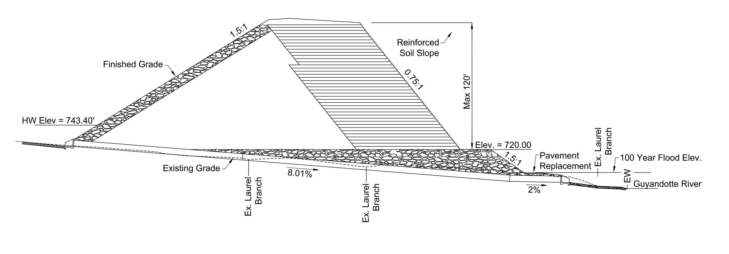
An embankment consisting of an MSE wall midslope or a 0.75H:1V RSS were considered as alternative options. Out of these two options, RSS was selected by the West Virginia Department of Transportation (WVDOT) as a feasible option due to the availability of on-site reinforced fill material and other considerations. The on-site soils consist of residual fine-grained to coarse-grained soils. Most of the embankment material was obtained from excavating on-site bedrock material and crushed and screened to meet WVDOT standard material specifications. RSS was proposed to extend from the top of the roadway embankment to a height of about 120 feet (36.6 m) at the deepest portion of the valley. A select embankment fill was placed within the proposed undercut up to an elevation of 720 feet (219.5 m) with a front slope configuration of 1.5H:1V, as shown in Figure 7. This configuration created an approximate 20- to 30-foot (6- to 9-m) wide bench at the toe of the highest portion of the RSS. A culvert that carries Laurel Branch through the embankment was constructed within the select embankment foundation material that is placed to an elevation of 720 feet (219.5 m) prior to construction of the RSS.
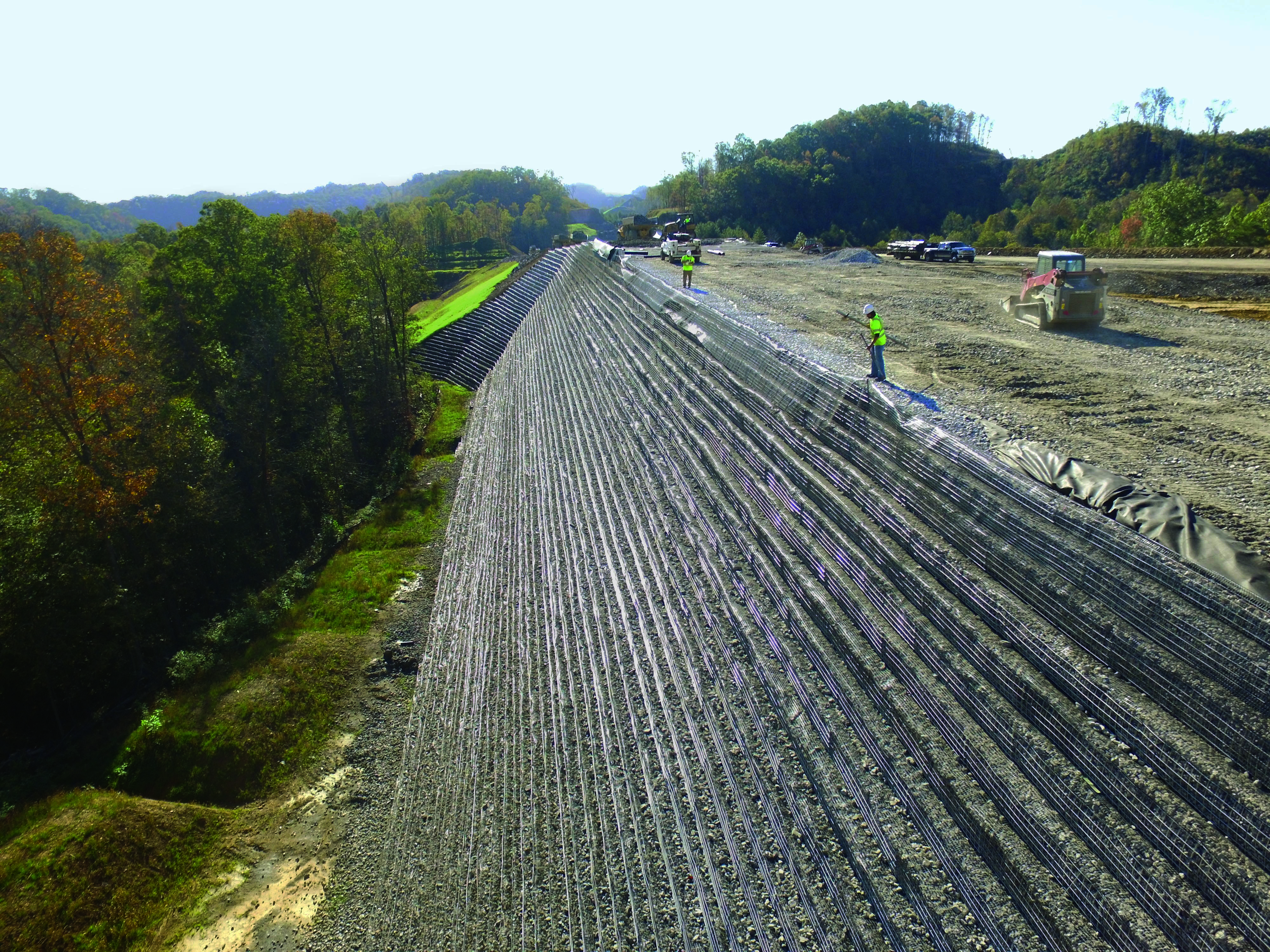
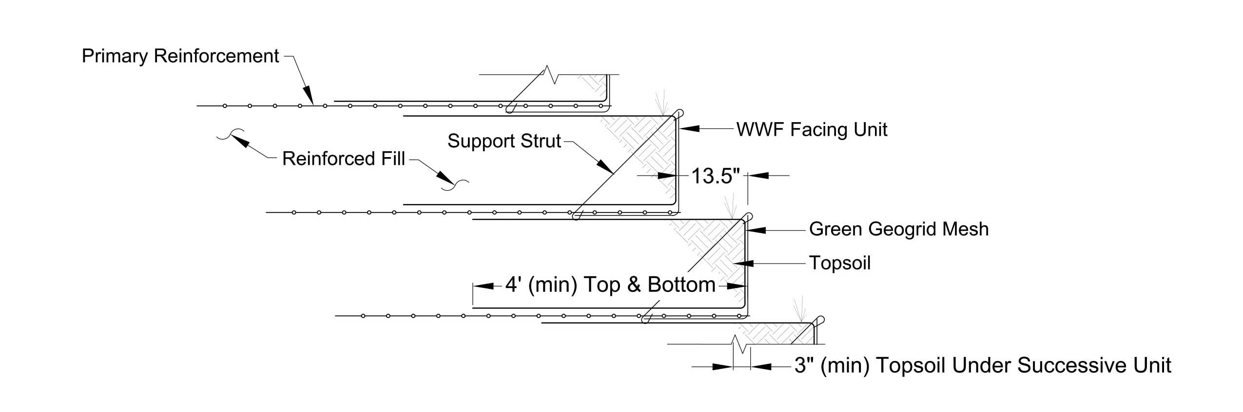
The computer program ReSSA 3.0 was used to design the reinforcement of the slope for a minimum factor of safety against global and compound failure. The obtained minimum long-term global stability safety factor for all the RSS cross sections met the WVDOT design criteria. The RSS was constructed with multiple layers of primary reinforcement using three types of uniaxial polyester geogrids vertically spaced at 18 inches (46 cm), and green geogrid mesh facing wrapped into the fascia and extended into the reinforced fill as secondary reinforcements. Uncoated welded wire forms were used in the facing to retain the fascia fill. Figure 8 shows welded wire form facing detail used in this RSS project, and Figure 9 shows the project postconstruction.

PROJECT HIGHLIGHTS
WV Route 10 RSS
Owner: West Virginia DOT
Location: CLyburn, W.Va.
General Contractor: Vecellio & Grogan Inc.
Design Engineer: Terracon Consultants Inc.
Fascia System: Welded wire form with TRM and vegetative facing
Geosynthetics Products: Maccaferri Uniaxial geogrids, Nonwoven geotextile
Geosynthetics Manufacturer: Maccaferri Inc.
U.S. Route 460 Connector—Phase II: Reinforced soil slope
A 6.2-mile (10-km) roadway alignment of U.S. Route 460 Connector–Phase II project is creating a new stretch of a four-lane divided highway that primarily serves as a connector to the future Coalfields Expressway from the community of Breaks, Va. The new roadway alignment traverses mountainous and densely wooded terrain with a wide range of geologic formations that predominantly consist of sandstone, shale and coal.

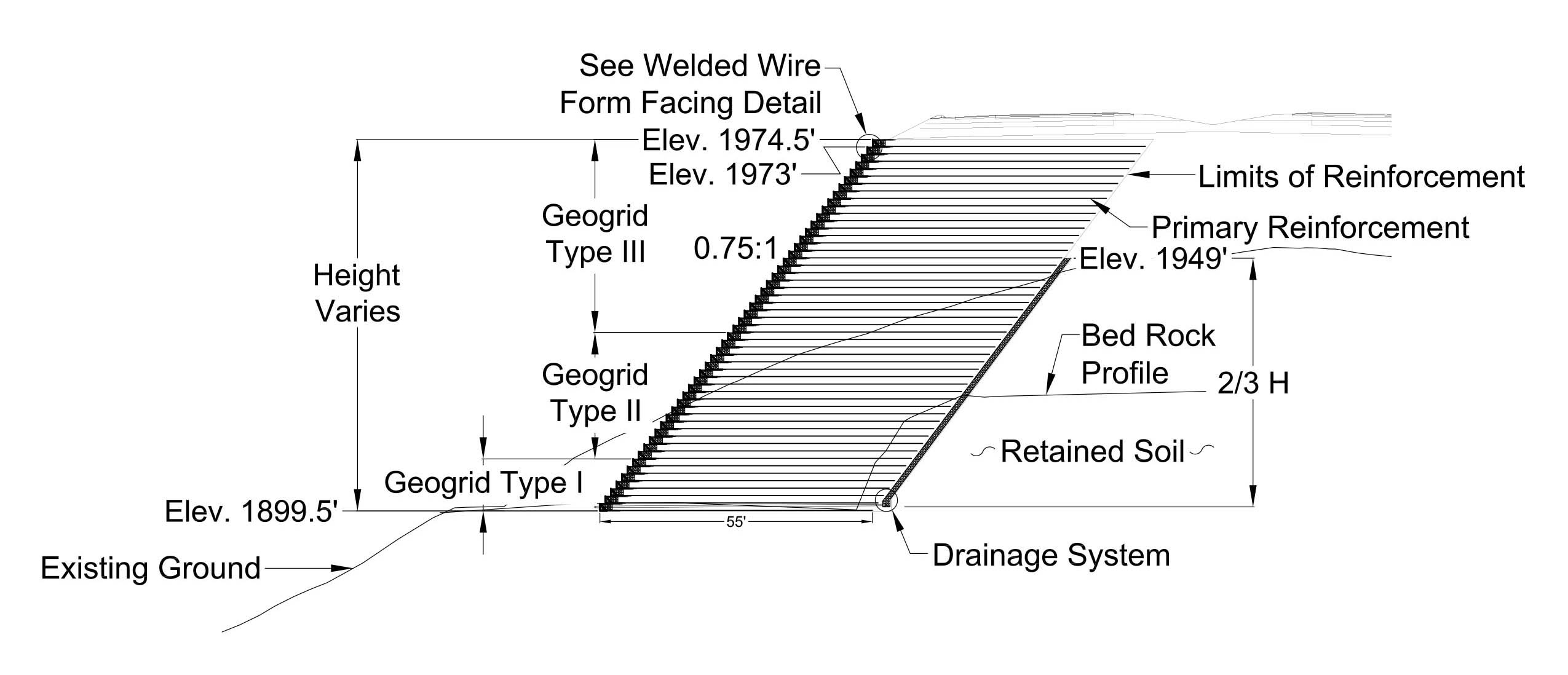
As part of this design-build project, welded wire-faced RSS ranging from 0.75H:1V to 1.5H:1V, with a maximum height of 80 feet (24 m), and extending a total length of 550 feet (168 m) was constructed along the project alignment to gain adequate roadway width. Alternately, very long and steep downslope embankments could have been constructed but would have significantly increased the cost, lengthened the construction duration and affected the forest. The RSS was founded on bedrock below or high enough above the coal seam and stretched through cut and fill areas. The RSS was constructed with multiple layers of primary reinforcement using uniaxial polyester geogrids vertically spaced at 18 inches (46 cm) and biaxial polypropylene geogrids wrapped in the fascia and extended into the reinforced fill as secondary reinforcements. Galvanized welded wire forms were used in the facing to retain the fascia stones. Figure 10 shows the welded wire form facing detail used in this RSS project.
Computer programs ReSSA 3.0 and Slide 6.0 were used to analyze the internal, compound and global stabilities of the proposed RSS. The design analyses included both circular and wedge failure modes for the representative RSS cross sections. The analysis outcomes from both programs showed similar factors of safety and failure surfaces.
Initially, the RSS was designed using soil parameters recommended in the geotechnical report. However, the sieve analysis report of on-site excavated and crushed material showed higher than desirable percentage of material retained on a 4-inch (10-cm) sieve. This gradation resulted in an unknown installation damage reduction factor, and on-site installation damage assessment was required. This stood to delay the project several weeks, as the construction of RSS was on a critical path. To avoid construction delays, the contractor was instructed to start constructing the RSS, provided the primary reinforcement was placed at 9 inches (23 cm) vertical spacing instead of 18 inches (46 cm) until the installation damage reduction factors were obtained. The on-site installation damage test results were consistent with the initial design assumptions, and, hence, the vertical spacing between the primary reinforcement geogrid was reverted to the original design spacing of 18 inches (46 cm). This being a design-built project, working closely with the contractor was important to promptly amend the design to account for the variations during construction. Figure 11 shows a typical cross section of this RSS project.
Conclusion
Compared to conventional soil-retaining structures, reinforced soil structures have obvious and significant benefits, including cost-effectiveness, simplicity of the construction technique, speed of construction and flexibility of the structure. Tall geogrid reinforced soil structures should be designed with project-specific consideration of geogrid installation damage, long-term geogrid characteristics (creep and durability) and soil-geogrid interaction behavior.
PROJECT HIGHLIGHTS
U.S. Route 460 Connector RSS
Owner: Virginia DOT
Location: Grundy, Va.
General Contractor: Bizzack Construction LLC
Design Engineer: The Collin Group
Fascia System: Welded wire form with biaxial geogrid and stone facing
Geosynthetics Products: Maccaferri Uniaxial geogrids, Nonwoven geotextile
Geosynthetics Manufacturer: Maccaferri Inc.