 TEXTILES.ORG

Reconstruction of Hennepin County State Aid Highway 112 is a multi-phase project. Phase 1 was completed in fall 2018. Phase 1 included reconstruction and widening of the existing roadway as well as the construction of a bike trail between the road and the lake. The roadway/trail alignment is adjacent to the shoreline of Minnesota’s Long Lake, where the existing 18-foot (5.5-m) high roadway embankment side slope extended down to the lake shoreline. Soil borings identified fill soils over a 20- to 25-foot (6.1- to 7.6-m) thick soft peat layer beneath 700 lineal feet (213 m) of the 1,400-foot (427-m) long section adjacent to the lake. To facilitate roadway embankment widening without encroaching into the lake and over the soft peat/muck, a geogrid-reinforced steep (1H:1V) slope (RSS) was constructed with a high-strength geotextile placed along 700 lineal feet at the embankment base (Figure 1). A 1H:1V RSS was chosen at this location to reduce the roadway/trail embankment fill encroachment into the lake. The 1H:1V RSS also kept the new widened roadway within its original embankment footprint, which reduced the potential for embankment instability and excessive settlement over the soft peat soils. An aerial photograph prior to roadway reconstruction is shown in Figure 2.

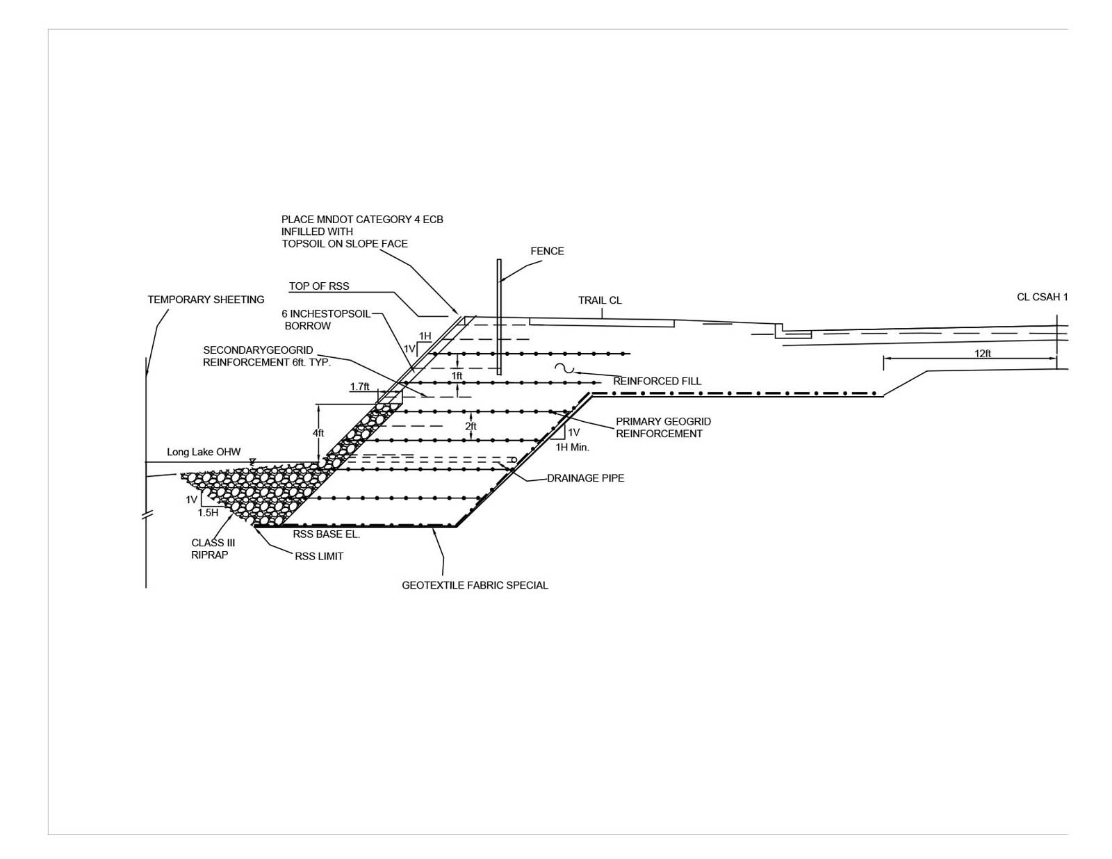
Unique site constraints required the 1,400-foot (426.7-m) long, 18-foot (5.5-m) high RSS to have some unique features. Stability analysis identified that a high-strength geotextile was required at the base of the RSS to maintain embankment stability over the deep soft peat/muck deposit. Additionally, the lower portion of the RSS was constructed beneath the Long Lake ordinary high-water level (OWL); a hydraulic analysis indicated that wave action could extend approximately 2–3 feet (0.6–0.9 m) above this elevation. This resulted in a riprap buttress being required at the base of the RSS and a 2-foot (0.6-m) thick riprap section placed on the lower portion of the RSS face. A typical RSS cross section is shown in Figure 3.
RSS construction staging, sheeting installation and dewatering
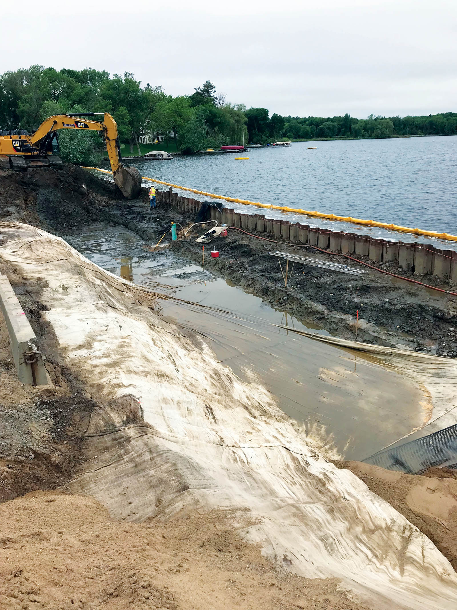
A temporary sheet pile driven in the lake and dewatering inside of the sheet pile were required to place the high-strength polyester geotextile and to construct the lower portions of the RSS, including the placement of the select granular embankment fill, uniaxial geogrid reinforcement and the riprap facing. The contractor constructed the lower portion of the 1,400-foot (426.7-m) long RSS in three phases, which included installing and removing the sheeting for each phase. This allowed the contractor to reduce the total amount of sheet pile required for the project.
RSS base reinforcement
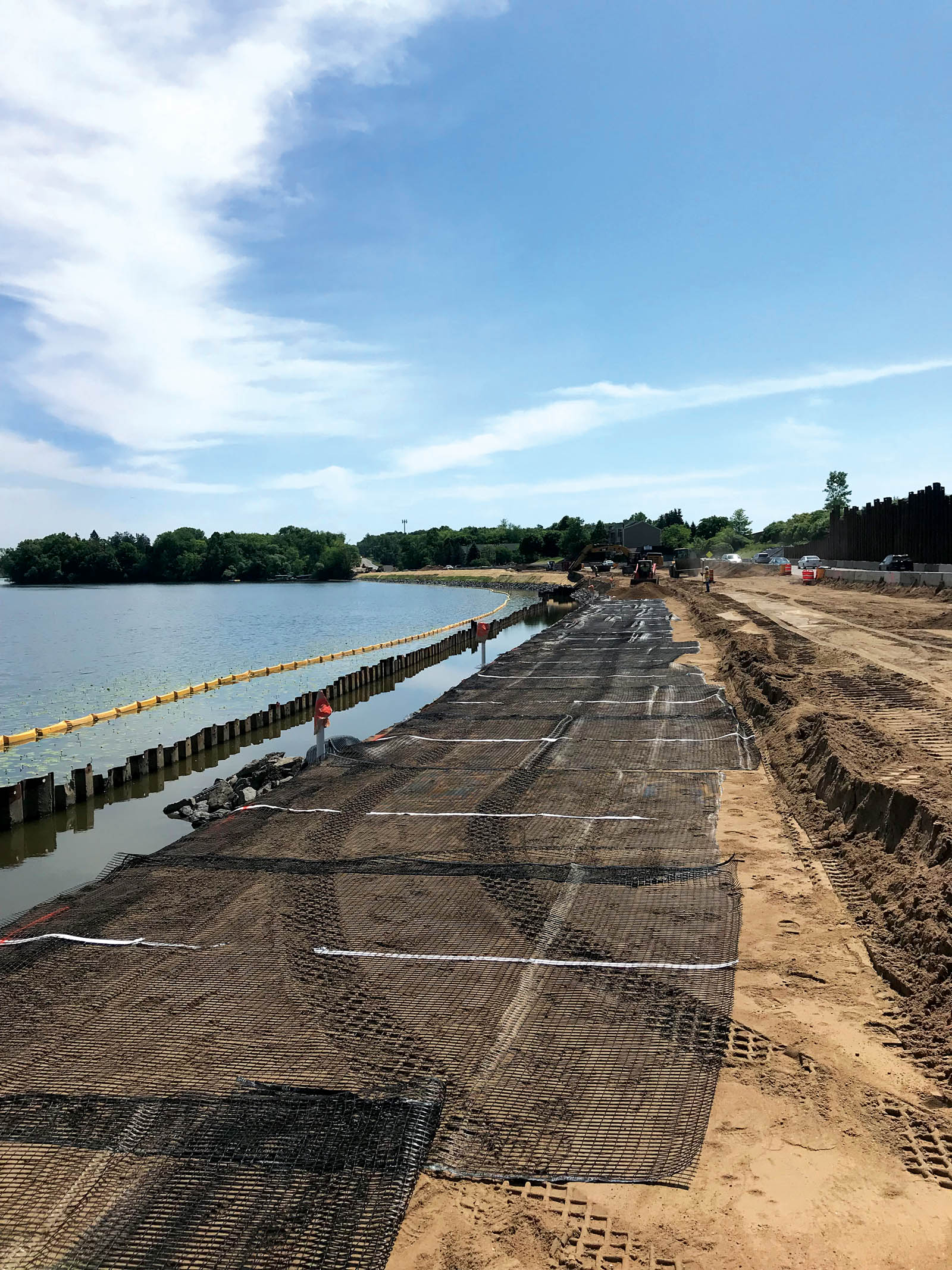
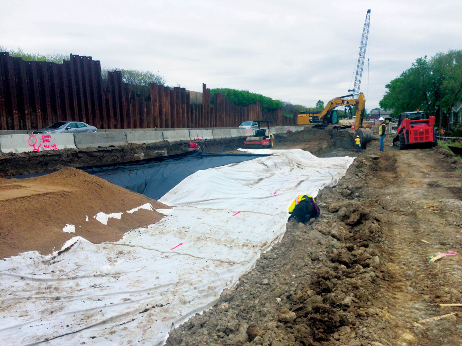
A portion of the RSS was constructed over the soft peat/muck deposit adjacent to the lake. Slope stability analyses indicated that a high-strength geotextile, with an ultimate tensile strength (ASTM D4595) exceeding 20,000 pounds-force/foot (292 kN/m) and a tensile strength of 10,000 pounds-force/foot (146 kN/m) at 5% strain, was required at the base of the RSS to maintain an adequate factor of safety with respect to embankment stability over the soft soils both during construction and over the long-term. A polyester geotextile was selected to meet the high-strength/high-modulus requirement. To satisfy embankment global stability and geotextile pullout requirements, the high-strength geotextile extended back into the embankment 70 feet (21.3 m) from the RSS toe. The geotextile was placed with its machine direction perpendicular to the slope face. To accomplish this and accommodate construction phasing, the contractor initially placed the geotextile beneath the roadway cut prior to RSS excavation. The remaining length of geotextile was folded up midslope and partially filled over to protect it from UV exposure. The contractor used a Jersey barrier to mark the location where the geotextile extended to. The lower portion of the embankment adjacent to the lake and inside the sheet pile wall was then excavated, dewatered, and the geotextile was unfolded and extended to the toe of the slope. The placement process is shown in Figure 4.
After unfolding, the remaining portion of the high-strength geotextile was deployed using hand-operated winches mounted to the sheet pile wall and pulling on ropes sewn into the leading edge of the geotextile. Five high-strength 15-foot (4.6-m) wide geotextile panels (75 feet [22.3 m] total width) were sewn together and then deployed at one time. The geotextile placement at the base of the RSS cut is shown in Figure 5.
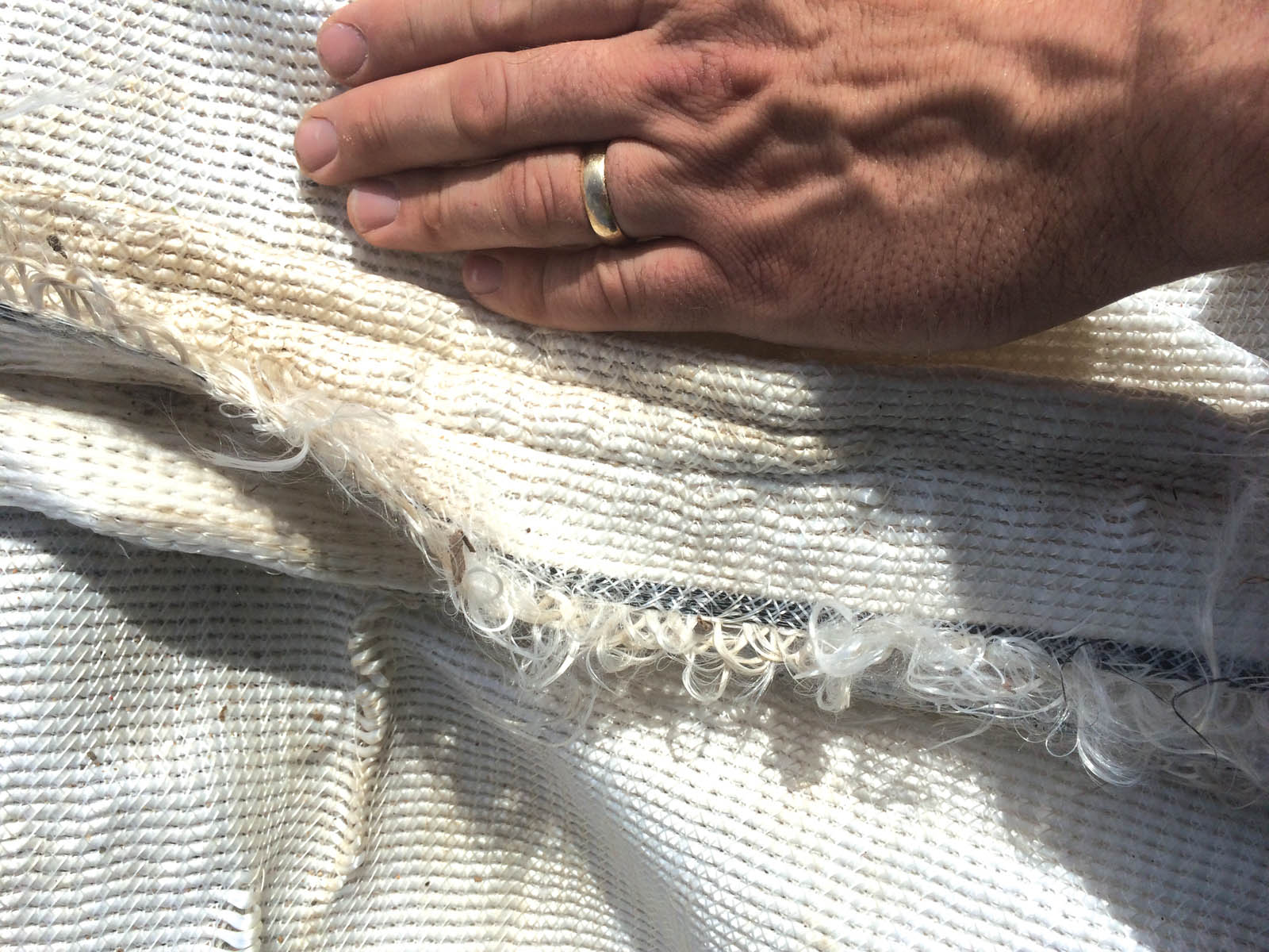
The adjacent geotextile panels were sewn together to facilitate uniform geotextile coverage along the RSS base and to facilitate embankment fill placement over the peat/muck soils. The 15-foot (4.6-m) wide individual geotextile panels were seamed together using a J-seam sewn with 277-denier thread, which has a tensile strength of 33 pounds-force/foot (0.5 kN/m). A seam strength of at least 1,000 pounds-force/foot (15 kN/m) was required by the project specifications. The contractor selected a J-seam with two rows of stitching. The high-strength geotextile had an ultimate tensile strength in the cross direction of 3,082 pounds-force/foot (45 kN/m); thus, the seam created was approximately 40% of this value, which is what was expected. A typical field seam is shown in Figure 6. The white thread on the white geotextile made the seam difficult to see.
In addition to the geotextile, the section of the RSS over the peat/muck was constructed using a staged loading technique with geotechnical instrumentation installed within the peat/muck layer to monitor excess pore water pressure dissipation and embankment settlement during construction. The staged loading was performed to maintain an adequate factor of safety with respect to embankment global stability during and postconstruction. The geotechnical instrumentation indicated that excess pore water pressures dissipated relatively quickly in the buried peat/muck layers. This dissipation allowed the contractor to accelerate fill placement rates over the soft soils and complete this segment of the RSS relatively quickly. Settlement plates installed within the soft ground area indicated 2–3 inches (5–8 cm) of total settlement in the underlying peat/muck layer. This settlement magnitude was within the range that was estimated during the project design. This small amount of settlement was a result of the design requirement that the new roadway/RSS embankment be constructed within the old embankment footprint, which was made possible by constructing the 1H:1V RSS instead of the more typical 4H:1V side slope.
RSS fill material and geogrid reinforcement
The RSS-reinforced fill consisted of a MnDOT select granular borrow material, which is a well-graded sand with a fines content less than 10% by dry weight. The RSS design required that the re-inforced fill material have an angle of internal friction of at least 35˚. The project specifications required the contractor to prequalify the granular material to be used for the RSS prior to construction by performing laboratory direct shear and compaction testing. The specified soil density was correlated to a dynamic cone penetrometer (DCP) penetration index, and the DCP was used for compaction quality control during construction.
The RSS primary geogrid reinforcement was required to have an allowable long-term tensile strength of 4,000 pounds-force/foot (58.4 kN/m) in the machine direction. The primary geogrid reinforcement was installed at 2-foot (0.6-m) vertical intervals at fixed elevations along the RSS alignment, with the geogrid strength direction oriented perpendicular to the slope face. The global and internal RSS stability analysis indicated that the primary geogrid reinforcement had to be placed in horizontal lengths of 18 feet (5.5 m), or approximately 100% of the slope height. Secondary geogrid reinforcement was placed at 1-foot (0.3-m) vertical intervals between the layers of primary geogrid reinforcement. The secondary geogrid reinforcement consisted of a biaxial geogrid with an allowable tensile strength of 1,000 pounds-force/foot (15 kN/m) in both the machine and cross directions. One hundred percent horizontal geogrid coverage was required at each reinforcement elevation. The primary geogrid reinforcement panels were abutted together with no mechanical connection between adjacent panels, while the secondary geogrid reinforcement was installed in a continuous manner with the geogrid roll direction parallel to the slope face.
RSS facing
The lower portion of the RSS was constructed beneath the Long Lake OWL, and hydraulic analysis indicated that wave action could extend several feet above this elevation. For erosion protection, a 2-foot (0.6-m) wide riprap buttress was used as the facing for the lower portion of the RSS. A needlepunched nonwoven was used as a filter between the granular RSS fill and the 18-inch (46-cm) diameter riprap. The geotextile had to be wrapped back at 2-foot (0.6-m) vertical increments to facilitate primary geogrid reinforcement placement.
Above the riprap section, a 6-inch (15-cm) thick special topsoil mixture was placed at the slope face. The topsoil specification required a specific seed and fertilizer mix to promote rapid and dense vegetation. A straw-coconut erosion control blanket was placed on the formed slope face to provide erosion protection prior to vegetation establishment. The project specification also required the contractor to periodically water the completed slope face during construction. The primary and secondary geogrid re-inforcement extended through the riprap and topsoil sections to the slope face.
Construction completion and summary
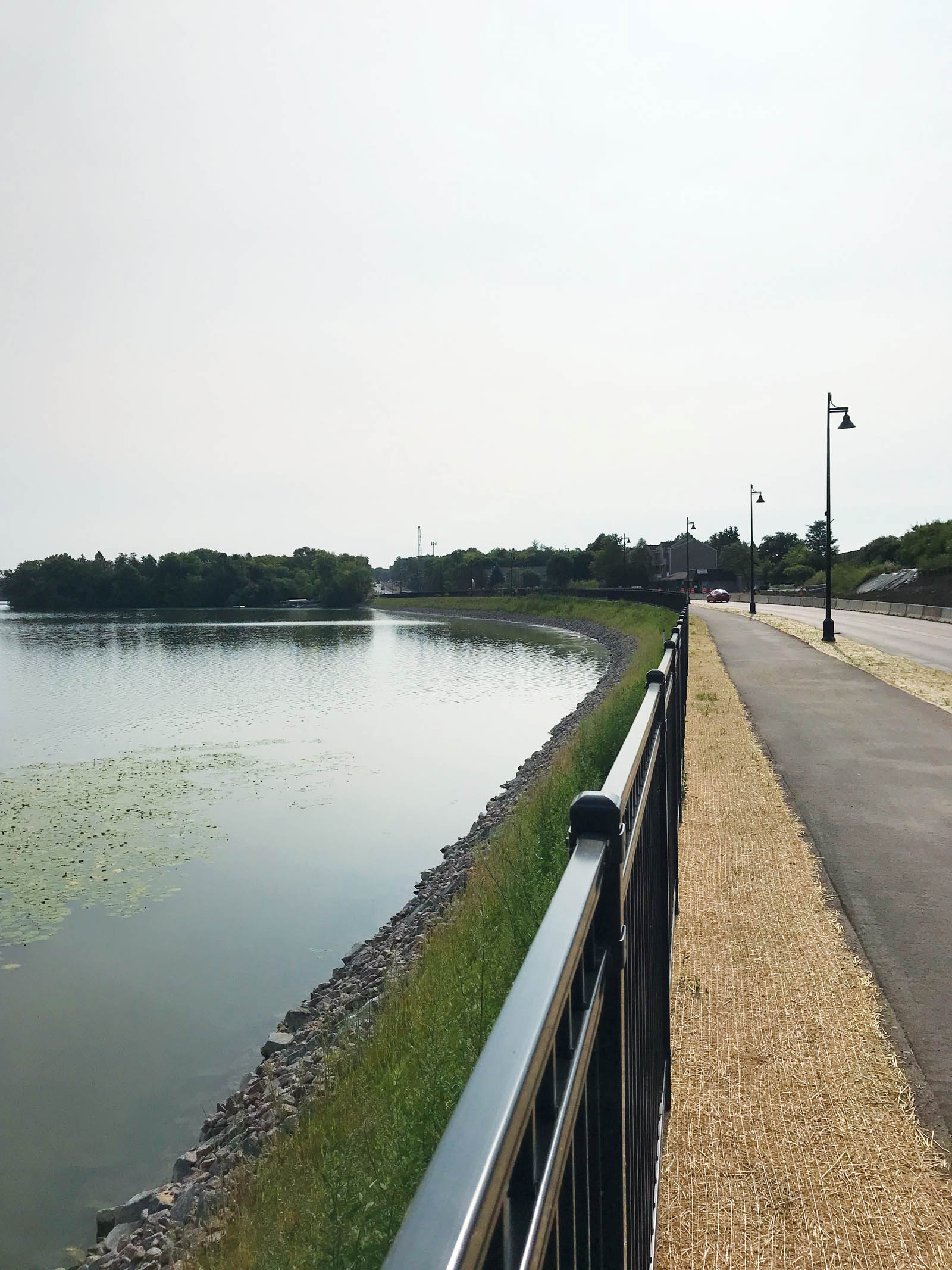
Construction of the 1,400-foot (426.7-m) long, 1H:1V RSS was completed in five months. The lower portion of the RSS was constructed in three 500-foot (152.4-m) long segments, with the contractor re-using the temporary sheet pile cutoff wall. Vegetation establishment along the upper portion of the slope began shortly after slope construction and was well underway once roadway and trail pavement was placed and the project was completed. The completed RSS is shown in Figure 7.
Nathan Lichty, P.E., M.ASCE, is a project engineer with Gale-Tec Engineering Inc. in Minneapolis, Minn.
Stephan Gale, P.E., D.GE., F.ASCE, is the president of Gale-Tec Engineering Inc. in Minneapolis, Minn.
Nathen Will, P.E., is a senior associate at SRF Consulting Group Inc. in Minneapolis, Minn.