 TEXTILES.ORG

California’s water infrastructure is one of the most challenged systems in the United States due to the large population it supports, the age of much of the water infrastructure, and the diverse environments—mountains, coastlines, old-growth forests, deserts—found in the state. The water infrastructure is also one of the country’s most advanced systems, in part due to the incorporation of geosynthetic barriers on a large scale.
Water security and conveyance efficiency are emphasized in California. Barrier geosynthetics excel in these applications.
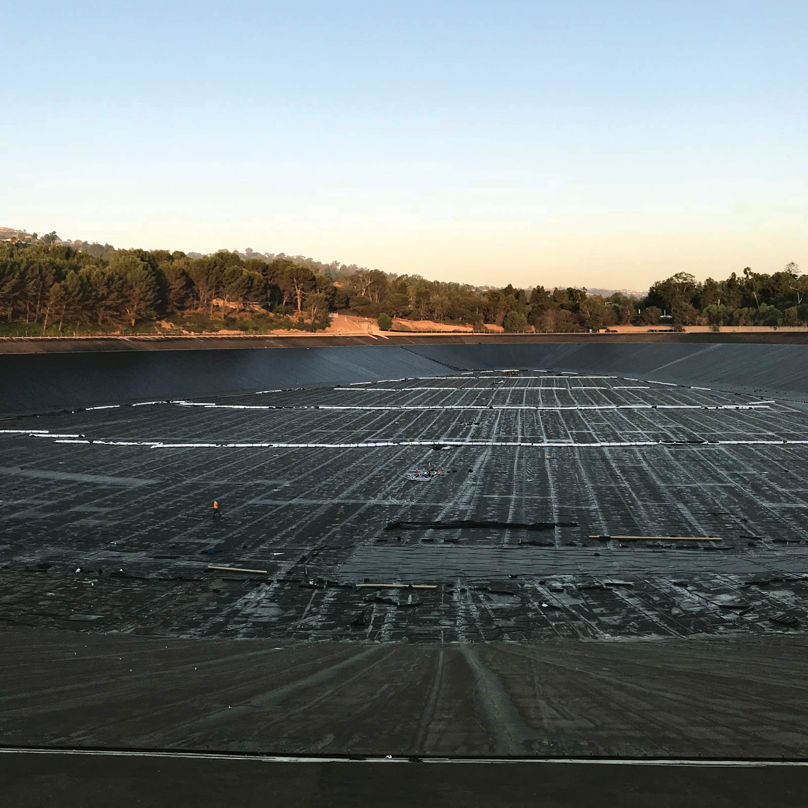
The Palos Verdes Reservoir (Figure 1) in Los Angeles County provides an exemplary case. The site has served the region for nearly 80 years. Its massive 360-million-gallon (1.36-billion-L) cell is nearing the end of a long and carefully planned process to revitalize the reservoir and greatly extend its service life.
In this series in Geosynthetics magazine, we highlight the project work from many angles to help tell the larger story of our shared field work. Part 1, which was published in the October/November 2016 issue, described the site parameters, design concerns, and how geosynthetic manufacturing and fabrication planning are utilized to keep the project moving toward its objectives. In Part 2 (April/May 2018), the series documented the full fabrication stage, site staging of materials, and installation planning for a more rapid execution in the wake of a significant site subgrade preparation delay.
Here in Part 3, we check in with the facility as it nears the recommissioning of its full operation. Part 4 will detail the final testing and filling of the reservoir, providing a full outline and view of the reconstruction of the Palos Verdes Reservoir.
Geosynthetic installation begins
As with any geotechnical work, certain stages must be carried out (generally addressing layers to be added) before others can be completed. If a delay occurs, it ripples through the project planning system. Because of this, geosynthetic installers often have elevated pressure to find more efficiency to help get a project back on track, to the extent possible, without sacrificing barrier system integrity and design safety.
At the sizable Palos Verdes site, this has certainly been the case. The installation team began with a soft start, due to the lack of prepared subgrade. The reservoir, shaped like an avocado, is designed with slopes at a depth of approximately 75 feet (23 m) and width of 200 feet (61 m). To optimize its storage security, the old concrete liner was to be replaced with a new asphalt liner overlain by an impermeable geomembrane lining system. (Utilizing geomembranes over another barrier element, like an asphalt liner, is an extremely effective storage design, particularly for deep cells.) A new floating cover was also designed into the facility for environmental security and evaporation control.
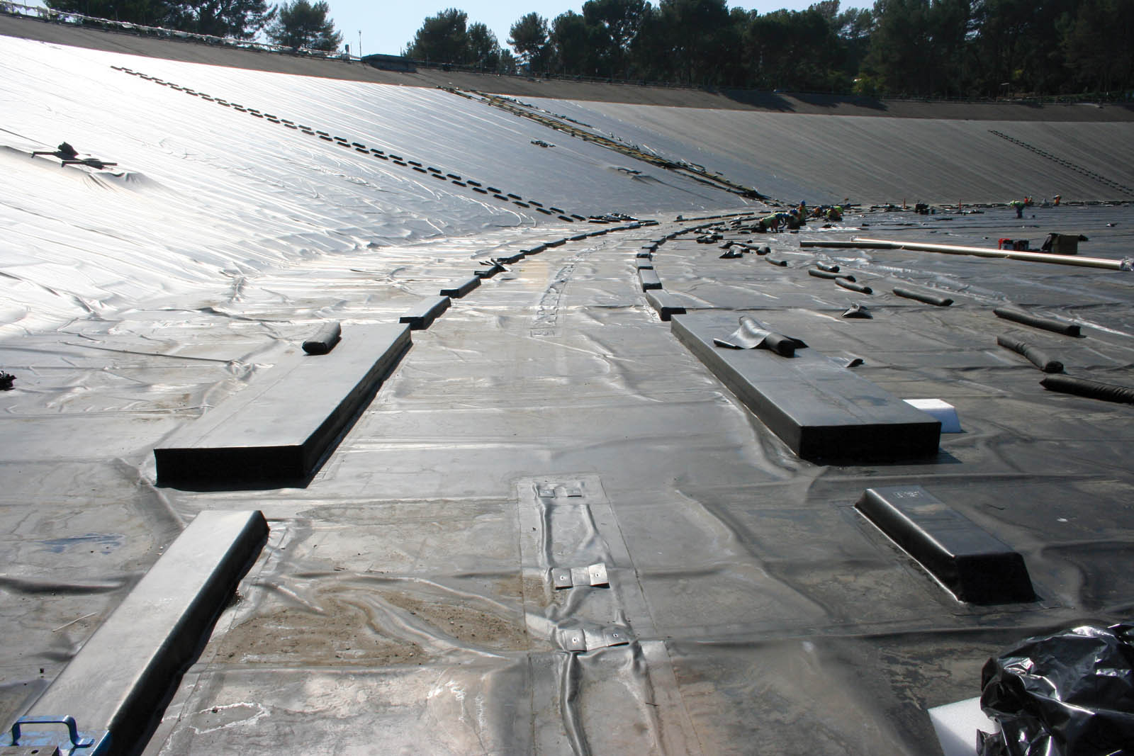
The project was delayed numerous times. While waiting for the subgrade work to be completed, the team used a smaller crew to achieve a safe installation. They began with bolting 4,300 linear feet (1,311 m) of material at the top of the reservoir. Additional staging at a safe storage facility helped the crew plan for efficient deployment of the 1.2 million square feet (111,000 m2) of 60-mil (1.5-mm) chlorosulfonated polyethylene (CSPE) geomembrane for the lining system and the same amount of 45-mil (1.1-mm) CSPE for the floating cover. They also adjusted the execution plan for the 1.2 million square feet (111,000 m2) of geocomposite material for the cell, sand tubes, float wraps/hatches, the rain collection trough (RCT) system and vents (Figure 2).
Once the subgrade was complete in mid-January 2018, the full installation crew arrived. They initiated the installation of the geocomposite and the 60-mil (1.5-mm) CSPE lining system.

Impact of the delay
The large volumes of CSPE barrier materials had all been manufactured in rolls of five-ply, 60-mil (1.5-mm) and three-ply, 45-mil (1.1-mm) and subsequently fabricated by Raven CLI at its California facility to expedite delivery. The fabricated panels were designed for specific placement points in the cell.
In many respects, this is where you can see a great difference between a “typical” geosynthetic barrier installation, such as is commonly performed at a landfill, and what happens with the heightened sensitivity of more complex infrastructure works, such as on Palos Verdes. Landfill design is not simple, but the installation procedures are generally far less crowded, and the work is replicated so often that from an execution standpoint the work is much easier (weather permitting).
At the reservoir, the crew began from what they called “home plate” and worked their way from west to east along the south wall. The 18-month delay from the original plan had affected the CSPE material. The rolls had been stored at or near the site and had cured in the interim. This meant that the site crews had considerably greater work to do to properly seam the large, prefabricated panels. The extensive prep work involved the use of a xylene/CSPE adhesive wash down and scrub. This process was essential to properly open the material for welding and to meet the specified field weld strength requirements.
The crew sequenced the work by installing and covering the geocomposite with the 60-mil (1.5-mm) CSPE geomembrane as close to the edge as possible. The specification required the geocomposite to be covered within seven days of installation, and the easiest way to accomplish this was to install the barrier layer.
The crew continued to work along the south wall until they reached the access ramp, which needed to be left open for construction access to the bottom for all trades. The installation team then moved to the north slope—past the access ramp—and began working their way toward home plate to tie in the walls on the barrier system.
Upon reaching home plate, the crew jumped to the floor and began working the lower zone lining system in rows. They finished a significant amount of that work in August and began the cover installation on the north side of the reservoir near the access ramp section.

Remaining tasks
Prior to closing the work on the cover, the Raven CLI Construction crew will install the small section of wall left open for the access ramp. This will be the last area covered with geocomposite, geomembrane and cover materials as the crew “paints” its way out of the reservoir.
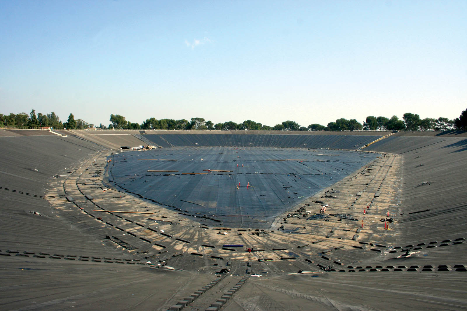
All access going forward will be done by walking down the 200-foot (61-m) slope to the base of the reservoir (Figure 3). Special care during this phase is required so there is no damage to the 60-mil (1.5-mm) liner or the 45-mil (1.1-mm) cover panels.
Once the system is installed and approved, inflation testing will be conducted on the floating cover system. That work will be performed in five sections, each of which will be isolated from the others by ballast tubes. Once the tubes are in place, the crew will place a fan on one of the hatches in that zone and begin to push air under the cover. The cover will lift and quality control (QC) personnel will enter under the cover to look for “star-lighting.” This is light that shows through, revealing any defects from under the cover. Even pinholes can be caught this way. Any concerns can be called to the top-side QC personnel for marking where repairs would be conducted.
The cover includes many complex elements and requires significant care during the installation and construction quality assurance (CQA) phases. For example, there are 14 hatches designed into the cover (Figure 4). These enable divers to access the reservoir for inspections. The hatches are built with floats using 316 stainless steel for long-term durability. Those hatches and floats were built off-site by a metals company, and assembled by Raven at its Colton, Calif., fabrication plant (Figure 5).
If any repairs are required in the cover, the system would be deflated, and the repairs executed. The inflation and inspection process would then be repeated.
When the inflation QC is completed, and any repairs have been finalized, ballast tubes will be moved into their final design position. This will enable the filling and chlorination stages, which are to be managed by the Metropolitan Water District (MWD). The stages involve washing down the lining system with a chlorine solution, followed by slow filling the reservoir while a chlorine mix is introduced per water-supply safety regulations.
The site team consists of MWD, OHL, Hilts Consulting Group and Raven CLI Construction. We want to thank all members of the team for their ability to manage a challenging project while delivering a world-class storage reservoir.
Filling commenced in early January 2019.
Long fuse, tough job and lots of lessons.