 TEXTILES.ORG

Introduction
The design of many geotechnical structures is based on limit-state conditions. For example, in designing gravity walls, the load exerted by the retained soil on the wall is based on an assumed active state of stresses. That is, the wall moves sufficiently outward, enabling the retained soil to mobilize its shear strength along a slip surface.
Depending on the soil, this movement could be very small. However, the shearing resistance of the soil reduces the resultant of active load acting on the wall. In design and through force equilibrium at a limit state (i.e., a state in which the soil mobilizes its strength along a slip surface), one seeks the highest value of this resultant. The outcome then is the active load needed for designing a stable wall.
Although not frequently used, the outcome also includes the corresponding critical shear surface of the soil wedge retained by the wall. Alternative to the active limit state, passive resistance may develop in front of the embedded portion of the wall as it is displacing into the resisting soil. To develop the full passive resistance, the shear strength of the soil in front of the embedded portion of the wall needs to be mobilized, albeit after larger movement than the active state.
For the passive limit state, the designer then seeks the lowest resistance. Limit-state equilibrium renders the minimum passive resistance and its associated failure wedge. This retaining wall example demonstrates that conventional design aims to accommodate worst-case, extreme-value conditions to ensure a stable gravity wall; driving loads are maximized and resisting loads are minimized.
Slope design abides to a similar mantra. In fact, it is more general and versatile than that of retaining walls. For a given soil profile and field conditions such as water and seismicity, one can assess the maximum mobilization of the shear strength of the soil while considering multiple feasible failure surfaces. Dividing the soil actual strength by its maximum mobilized resistance for a given slope’s many potential failure surfaces renders a minimum factor of safety (FS), the objective of slope-stability analyses. A common technique to assess stability of slopes is limit equilibrium (LE) analysis. The same versatile approach can assess the maximum load that a footing can carry before fully mobilizing the soil strength, the resistance of an anchor embedded in fill, or the maximum active load on a wall. LE analysis has been used successfully for many decades in complex geotechnical designs.
Design of geosynthetic-reinforced soil can be viewed as a subset of LE slope-stability analysis. Consequently, rational design of complex reinforced problems can be conducted without the need for empirical distinction between reinforced walls and slopes. In the context of reinforced walls, it can account for facing effects and toe restraint at a limit state. In fact, it can be used to rationally determine the load in a geosynthetic at its connection to the facing.
Technical details of the LE analysis as related to designing geosynthetic-reinforced soil structures have been published recently (Leshchinsky et al. 2016). It is an extreme-value problem in which, for a given layout of reinforcement, one seeks the distribution of maximum load in any geosynthetic layer, at any location, including at the connection, to uniformly mobilize the soil strength along any surface within the soil mass. The result is termed a baseline solution, as it provides the basis for adequate selection of reinforcements and connection specifications. That is, rather than dealing with specific products, the baseline solution enables the designer to economically select geosynthetics and connectors having sufficient long-term strengths.
Example Problems
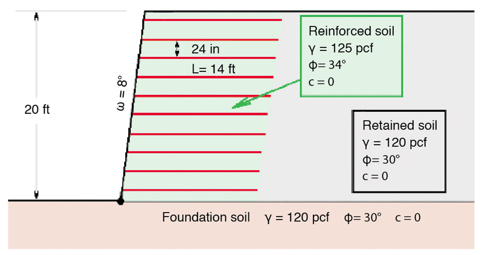
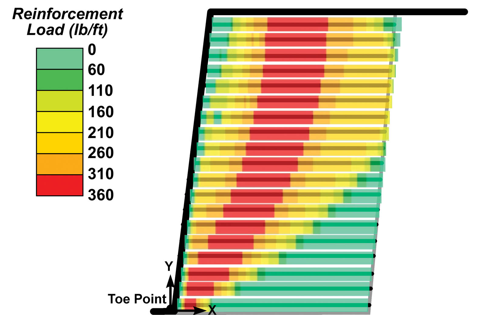
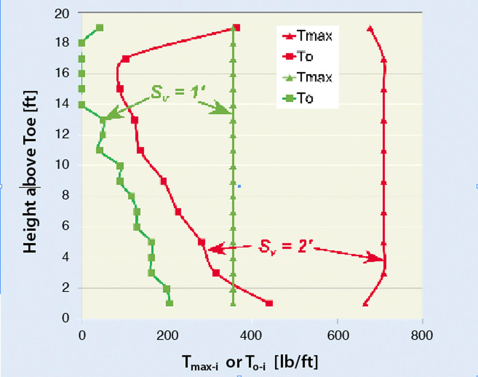
The baseline problem was presented in Part 1, and it is depicted in Figure 3, which is reprinted on page 23. Decreasing the reinforcement spacing from 2ft to 1ft will decrease the maximum load in each reinforcement layer, Tmax, proportionally as seen in Figures 13 and 14. However, the impact of close spacing is more significant in the connection loads. This load rapidly decreases, getting to negligibly small values in some layers. That is, the load in the reinforcement decreases, while the front-end pullout in each layer remains unaffected. As a result, for close spacing only a small upward shift of the front-end pullout envelope is needed to enable the development of reduced load in the reinforcement.
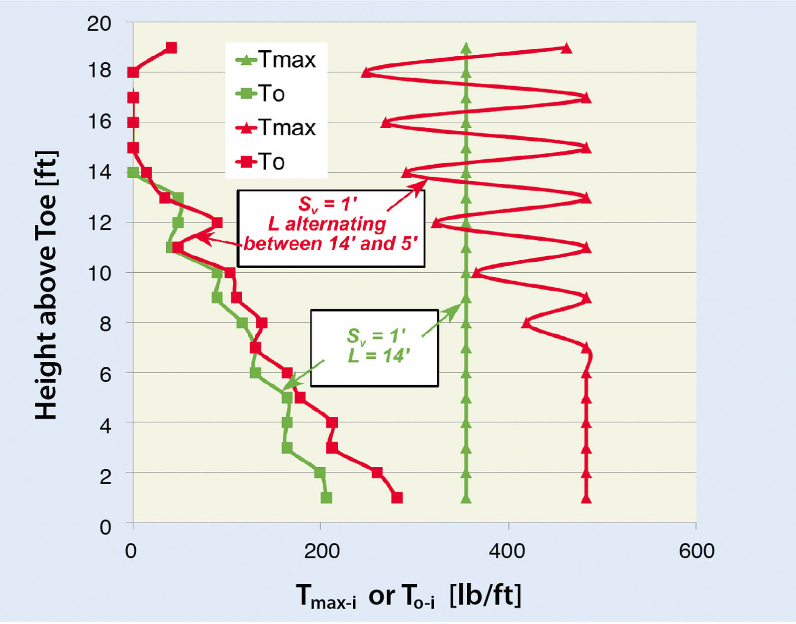
An alternative to full-length, closely spaced reinforcement is using alternating length of layers (i.e., primary reinforcement is full length while secondary or intermediate reinforcement is short). Figure 15 shows the tensile force distribution for such a case—it should be compared with the results shown in Figure 13, considering that the close spacing in Figure 15 is at the front. That is, the reinforcement is spaced 1ft apart in the front while the length of the reinforcement is alternating between 5ft and 14ft rather than being a uniform 14ft long, as in Figure 13. Figure 16 indicates that Tmax is being affected but it will greatly depend on the length of the intermediate layers. However, the connection load significantly decreases, producing essentially the same load for full-length, closely spaced reinforcement as for intermediate layers. Note that one needs to also check global stability. It turns out that the shorter reinforcement may render inadequate compound FS=1.21. A few percent increase in the reinforcement strength rendered by the baseline solution would produce FS=1.30.
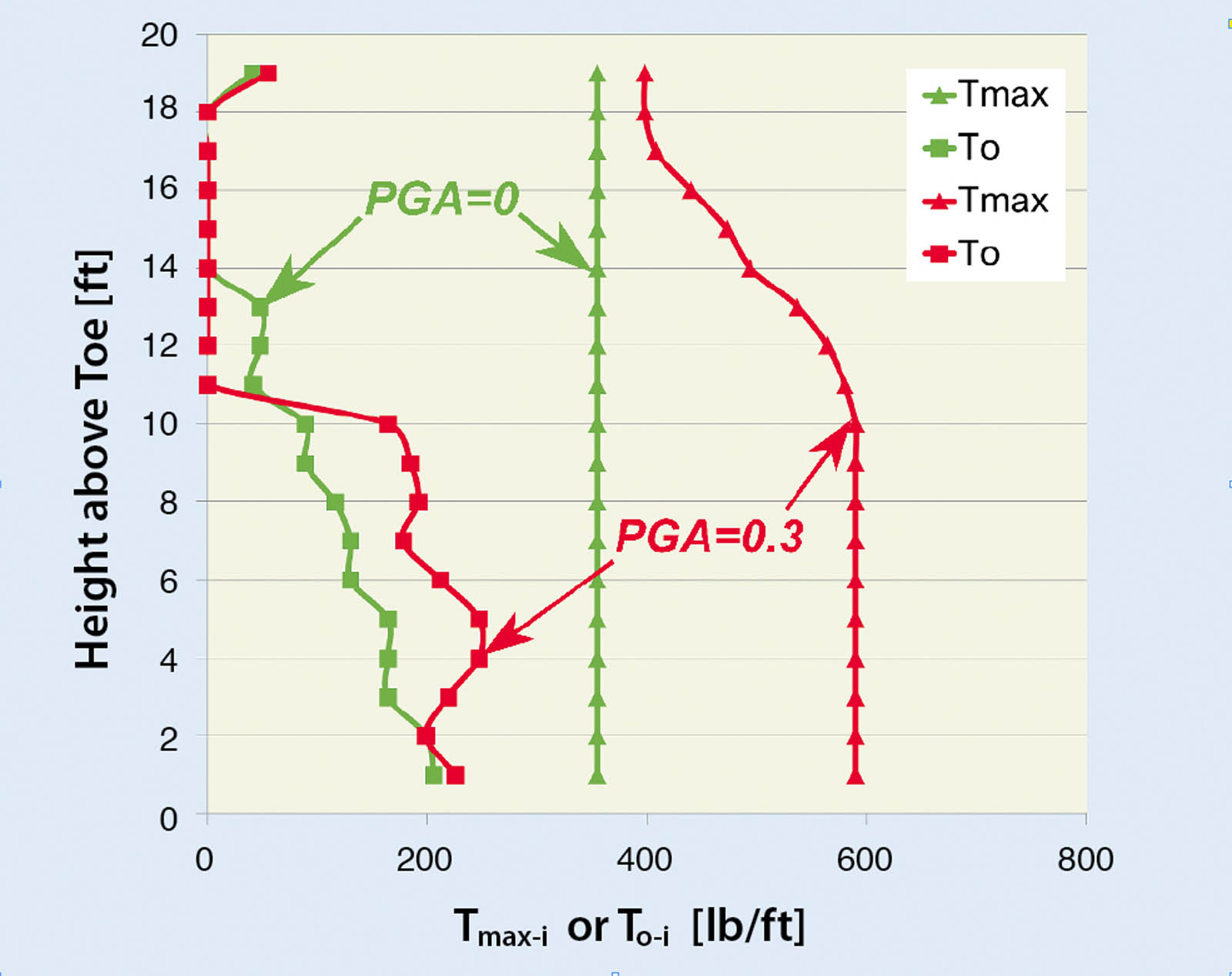
Figure 17 shows the effects of seismicity when the reinforcement is closely spaced. In this example, the selected peak ground acceleration (PGA) is equal to 0.3g. In slope-stability design, it is customary to consider in the limit equilibrium equations half the specified PGA (i.e., 0.15g). It is a realization that pseudostatic analysis is conservative, especially for flexible systems. This practice has been established based on lab and field data. As can be seen, the load in the reinforcement increases due to seismicity. Upper layers reach their pullout resistance capacity because of low overburden pressure and, therefore, their contribution to stability is limited. Consequently, loads carried by lower layers increase, ensuring that the prescribed FS is indeed attained. Interestingly, the connection load does not increase as much. This insensitivity can be realized from Figure 18; seismicity tends to generate deeper slip surfaces requiring larger loads in the reinforcement away from the facing. It is noted that the inertia of facing has not been used in this example. However, it can be easily implemented. For small facing, this inertia is not very significant.

Figure 19 shows the data for a complex example problem. Using the terminology of the American Association of State Highway and Transportation Officials (AASHTO), the lower tier is considered a reinforced wall whereas the upper tier is a reinforced slope. Note that the retained soil is a sandstone with substantial cohesion (i.e., it is likely to be stable regardless of the reinforced system in front of it).
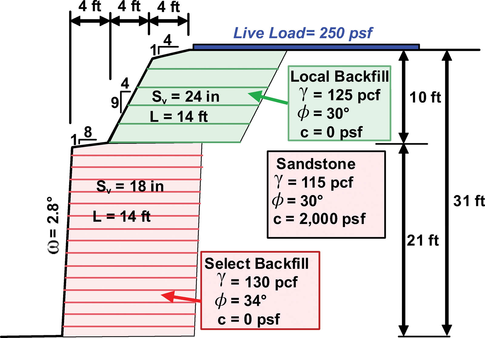
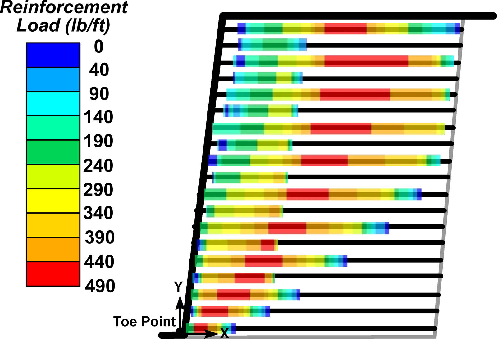
Figure 20 shows the distribution of loads along each reinforcement layer. The effects of the upper tier are seen in the frontal zone of reinforcements in the lower tier where there is jump discontinuity in loads.
The long-term strength of reinforcement determined from the baseline solution is 1,055 lb/ft. This value has been determined using Figure 20 where Tmax is about 703 lb/ft leading to the maximum capacity or Tult=2,110 lb/ft. Consequently, the long-term design strength is equal to Tult/RF=2,110/2.0=1,055 lb/ft whereas RF is a combined reduction factor for creep, durability, and installation damage. Using this value in global stability, FS is about 1.36—see Figure 21. The associated critical circle is illustrated on the safety map in Figure 21. Clearly, the cementation of the sandstone makes that zone stable while the reinforcement ensures adequate stability of the backfill material.
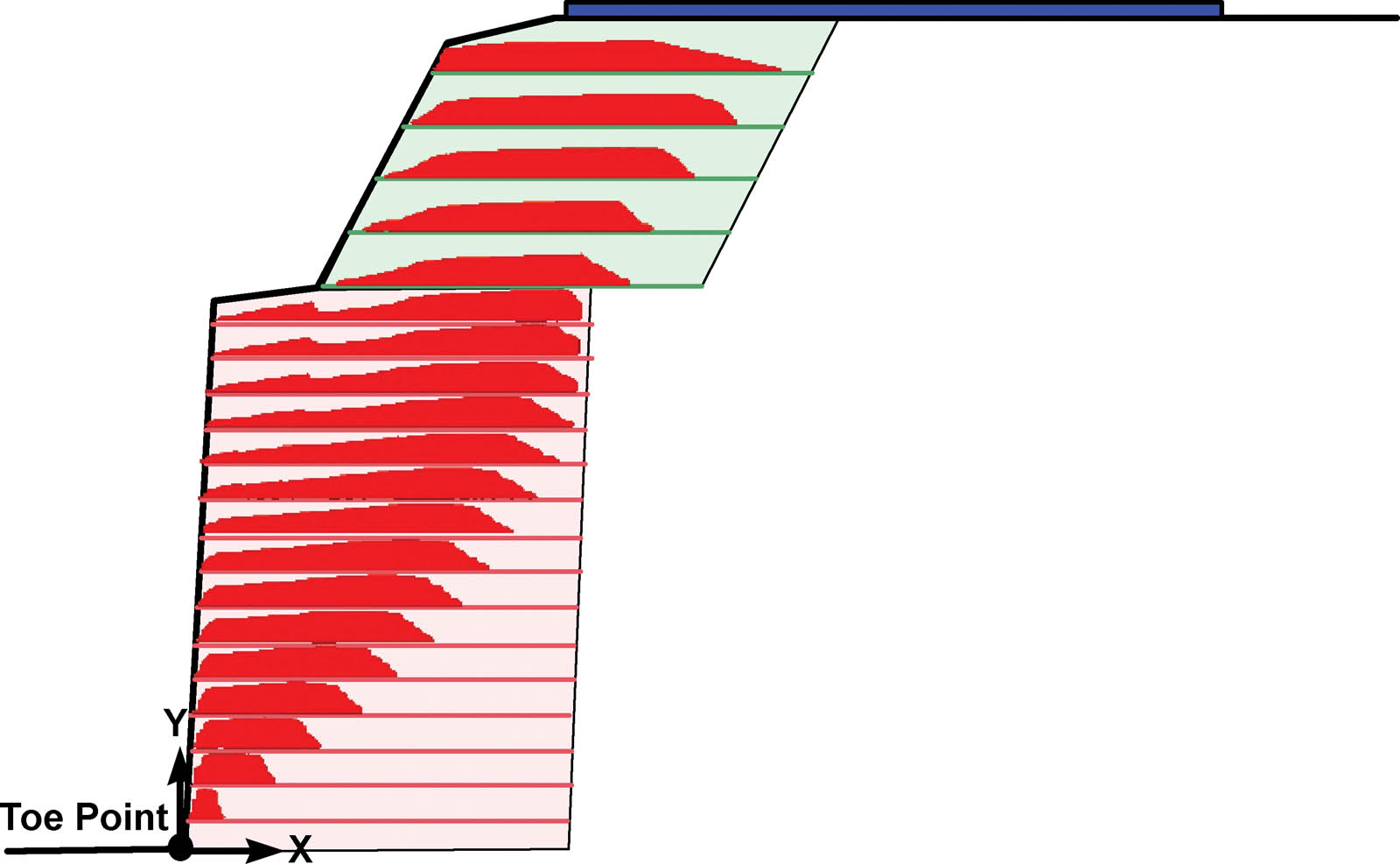
Figure 22 considers the effects of facings that are 1ft deep and 8in. high, having block-to-block friction of 35˚ and “cohesion” of 1,000 lb/ft. Note that this is not real cohesion but rather a convenient representation of interblock shear strength. The shear resistance at the interface of the leveling pad with the foundation soil is ignored. Comparing Figures 20 and 22 (note that in each figure a different scale is used for the load distribution), one sees that the block-to-block shear strength affects the distribution of load in the reinforcement, rendering small loads at the front. However, loads in the reinforcement are needed to prevent toe failure (i.e., avoid slip surfaces emerging through the toe where, in this example problem, the leveling pad has no shear resistance). Tmax in Figure 22 is about 20% smaller than that in Figure 20, indicating that the facings decrease Tmax. Not shown here is the significant decrease in connection load due to the facing effects.

Conclusion
The methodology or framework used can be considered fundamental. It produces the baseline solution consisting of the distribution of load along each reinforcement layer as well as the load at the connection. The approach is a rational extension from slope stability analyses. It can consider complex problems such as tiered systems, layered soil profiles, water, irregular layouts (e.g., secondary reinforcement), interaction between the reinforcement and the surrounding soil, seismicity, and facing units. It eliminates the need for different internal stability and external stability analyses while being equally valid for reinforced walls and slopes. The methodology identifies the conditions that lead to a limit state (i.e., a system that is on the verge of failure). However, with an imposed prescribed FS, the approach renders a reinforced system with adequate margin of safety. For convenience, Bishop’s method has been used in this article; however, the framework can be used with any applicable slope stability analysis, including planar surface (Coulomb 1776), log spiral (Leshchinsky and Boedeker 1989), or any method of slices (Spencer 1967, Janbu 1973, and Morgenstern and Price 1965).

References
Baker, R., and Leshchinsky, D. (2001). “Spatial distribution of safety factors.” J. of Geotechnical and Geoenvironmental Eng., 127(2), 135–145.
Coulomb, C. A. (1776). “Essai sur une application des règles des maximis et minimis à quelques problèmes de statique relatifs à l’architecture.” Memoires de l’Academie Royale, 7, 343–382 (in French).
Janbu, N. (1973). “Slope stability computations.” In Embankment Dam Engineering, R. C. Hirschfeld and S. J. Poulos, eds., Wiley, New York, 47–86.
Leshchinsky, D., and Boedeker, R. H. (1989). “Geosynthetic reinforced soil structures.” J. of Geotechnical Engineering, 115(10), 1459–1478.
Leshchinsky, D., Leshchinsky, O., Zelenko, B., and Horne, J. (2016). “Limit equilibrium design framework for MSE structures with extensible reinforcement,” Report FHWA-HIF-17-004, Federal Highway Administration.
Morgenstern, N. R., and Price, V. E. (1965). “The analysis of stability of general slip surfaces.” Geotechnique, 15(1), 79–93.
Spencer, E. (1967). “A method of analysis of the stability of embankments assuming parallel inter-slice forces.” Geotechnique, 17(1), 11–26.
Dov Leshchinsky, Ph.D., is professor emeritus of civil and environmental engineering at the University of Delaware and a partner at ADAMA Engineering in Clackamas, Ore.
Ora Leshchinsky, P.E., is a partner at ADAMA Engineering in Clackamas, Ore.
Ben A. Leshchinsky, Ph.D., P.E., is an assistant professor at Oregon State University.
All figures courtesy of the authors.