 TEXTILES.ORG

Introduction
The mechanisms that govern unpaved road performance are complex, and accurate field evaluation of the performance of unpaved roads incorporating geosynthetics is not easy because it involves many influence factors. Interpretation of test data can be correct only if there is a good understanding of the mechanisms (which was the purpose of the Part 1 article), rigorous planning of the field tests (which was the purpose of the Part 2 article), and appropriate implementation of the field tests (which is the purpose of this Part 3 article).
This article will focus on construction of test sections, representativeness of test sections, implementation of field evaluation, and interpretation of test results.
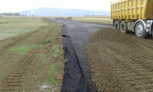
Construction of test sections
A construction plan should be prepared and discussed with the geosynthetic supplier. For both subgrade and base preparation, accurate measurement of ground levels is necessary for calculating base thickness and ensuring consistency. Specific considerations are presented below.
Subgrade preparation
The construction of a test section should start with the removal of topsoil, which often contains vegetation and organic matters. The subgrade should be graded or compacted to a level surface without any apparent voids. As a general rule, preparation and subsequent trafficking of all test sections should be consistent. The following constraints apply to construction equipment:
- In the case of natural subgrade soil, efforts should be made to minimize construction equipment traffic directly on the subgrade. If extra space is available, excavation and grading should be conducted from the sides of the test section. Otherwise, only the minimum required construction traffic to prepare the subgrade should be allowed. No further construction traffic is then allowed.
- In the case of compacted subgrade soil, construction equipment is allowed directly on the subgrade during construction but is not allowed after subgrade preparation.
Even though natural subgrade presents the drawback of being heterogeneous, it is preferred to compacted subgrade, especially when large test sections are needed. This is because constructing a uniformly compacted subgrade in a large area is very difficult. However, when a subgrade soil of a specific strength or CBR is required for test sections, a compacted subgrade soil may be used, with the following precautions:
- The soil to be compacted should be well mixed with water (if needed), which requires sufficient time for moisture content to even out across the section. Then, the soil must be placed and compacted in a consistent way.
- If soil is placed inside a trench to prepare a compacted subgrade, measures may be taken to maintain moisture of the compacted subgrade if needed. If the test site is expected to be subjected to rainfall during the test, a properly designed drainage system with equally spaced drain outlets should be installed in each test section; otherwise, the compacted subgrade soil may be ponded with water, which reduces subgrade strength and modulus.
Geosynthetic placement
Generally, the recommendations of the relevant geosynthetic manufacturers should be followed. The geosynthetics should be placed directly and flatly on top of the subgrade. If the width of the test section is wider than the roll or panel width of geosynthetic, additional geosynthetic should be installed and connection between the two pieces should be done by overlap or jointing. The overlap or jointing recommendations of the relevant manufacturers should be sought and followed where possible. In addition, the following recommendations may be considered, depending on the type of geosynthetic:
If geotextiles are used, Holtz et al. (2008) suggest a minimum unsewn overlap of 0.3–0.45m (12–18in.) for subgrade CBR > 2%, 0.6–0.9m (24–36in.) for subgrade CBR = 1–2%, and 0.9m (36in.) for subgrade CBR = 0.5–1%. Alternatively, the geotextile can be sewn for subgrade CBR < 1%. Geotextiles that are expected to act as tensioned membrane should be sewn. All geotextile roll ends should be overlapped for 0.9m (36in.) or sewn.
- If geogrids are used, an overlap of 0.3–0.45m (12–18in.) is often used.
- If geocells are used, connection should be done using staples.
Base course construction
Construction of a base course should follow the following typical procedure:
The mechanisms that govern unpaved road performance are complex, and accurate field evaluation of the performance of unpaved roads incorporating geosynthetics is not easy because it involves many influence factors.
- If multiple trucks are required to deliver granular material to a test site, it is important that all material is dumped and mixed together on site to prevent segregation and reduce variability between loads of material in terms of grading and moisture content.
- Granular material should be end-dumped and cascaded over the geosynthetic using construction equipment. The starting granular material thickness is a function of the subgrade strength. The preferred thickness of each lift after compaction is 0.15m (6in.) to 0.20m (8in.). When a base course is too thick (e.g., greater than 0.3m or 12in.) to be placed in a single lift, it should be divided into two or more lifts. When two or more lifts of granular material are placed, they should be placed in equal or similar lift thickness to avoid non-uniform base densities in depth. A well-graded granular material with fine particles should be compacted at its optimum water content within ±2% tolerance.
- It is important to ensure that the construction traffic is equal over all sections. All fill should not be brought in from one end, resulting in greater construction traffic over the initial sections.
- Depending on the type and quality of granular material used, pneumatic compaction equipment may be needed in lieu of a steel drum. Low ground contact pressure equipment can be used to perform placement of aggregate. This equipment should make complete passes over all sections. All passes should be recorded to be reviewed in the event that there are unexplained differences in test results. Video records can be used to substantiate this information. It is preferable that local compaction practice be followed.
- After placement and compaction of all lifts, the final compacted base thickness should be equal to the design base thickness.
Representativeness of test sections
To evaluate the performance of unpaved roads incorporating geosynthetics, representative test sections should be designed and prepared. To prepare representative test sections, the following factors should be considered.
Required number of test data
For test results to be reliable, a required number of test data is needed statistically. The basic formula to estimate the minimum number of test data assuming a normal distribution is:
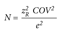
where N = required number of test data; zR = standard normal deviate, which depends on a confidence level; COV = coefficient of variation (%); and e = allowable margin of error (%). The standard normal deviates corresponding to 90% and 95% confidence levels are 1.645 and 1.960, respectively.
At different COV (from 10% to 30%), allowable margin of error (5% or 10%), and confidence level (90% or 95%), the required number of test data can be determined as provided in Table 1.
If a test site can be constructed with a subgrade strength COV lower than 20% as an example, 11 to 16 subgrade strength tests are needed if the allowable margin of error is 10%, as shown in Table 1.
| Confidence level (%) | COV=10% | COV=20% | COV=30% | |||
|---|---|---|---|---|---|---|
| e=5% | e=10% | e=5% | e=10% | e=5% | e=10% | |
| 90 | 11 | 3 | 44 | 11 | 98 | 25 |
| 95 | 16 | 4 | 62 | 16 | 139 | 35 |
Uniformity of subgrade and base
The representativeness of test sections is significantly affected by variability of subgrade and base. Indeed, Han and Giroud (2012): (i) demonstrated that variation of subgrade soil at a low CBR value (e.g., CBR < 1%) has more effect on the performance of unpaved roads than that at a high CBR value (e.g., CBR > 1%); and (ii) calculated in a specific case that a 10% base thickness increase resulted in 100% to 330% increase of the service life of the considered unpaved road.
To ensure the validity of test sections, subgrade and base should be uniform. To ensure uniformity of subgrade and base, density tests should be performed during and after construction of test sections and typical density requirements should be followed. In addition, the COV values for subgrade strength and base modulus for all test sections should be lower than 20% and the allowable margin of error for the average value of each parameter with respect to its target value should be less than 10%. The COV values for individual test sections should be lower than 10%. The deviation of the compacted base thickness from the target thickness should be smaller than 13mm (0.5in.). If the COV values for the test sections are higher than 20% or the COV values for individual test sections are higher than 10%, closer examination is needed and the number of tests at least needs to be doubled. To minimize moisture variation due to rainfall, a drainage system should be properly designed and installed in test sections.
Size of test section
Test sections should be large enough to be representative. There is a general rule in geotechnical research that the size of the test section should be at least five times the loading plate size to avoid a boundary effect. The influence depth of a circular or square loading plate is two times the plate size. In the case of a loading plate size of 0.3m (1ft), these rules lead to the following:
- The size of the test section should be at least 1.5m × 1.5m (5ft × 5ft).
- For a circular or square loading plate, the depth of the test section should be at least two times the plate size (i.e., 0.6m [2 ft]).
Two- or three-axle dump trucks have been mostly used for trafficking tests in the field. Rear axles carry most of the truck load. An accelerated pavement testing (APT) facility has also been used for the same purpose, which may employ a full axle or a half axle. Commonly used wheel configurations include single wheel, dual wheels, and tandem wheels. To minimize possible boundary effects, a test section for the trafficking test by a full-size truck in the field or a full axle in an APT facility should be at least 6.0m (20ft) long, 4.5m (15ft) wide, and 1.2m (4ft) deep (including the base and the subgrade). A test section loaded by a half axle in an APT facility should be at least half of the plan dimension (i.e., 3m [10ft] long and 2.3m [7.5ft] wide) as that tested by a full-size truck or a full axle.
Implementation of field evaluation
Instrumentation
To investigate load transfer mechanisms and stress distribution, earth pressure cells and strain gauges may be used. Also, when a test section consists of sensitive soil, piezometers may be used to monitor accumulation of excess pore water pressure in the soil. All these sensors should be prepared and calibrated in the laboratory before they are installed in the field. The following comments are related to the use of earth pressure cells:
- Earth pressure cells placed horizontally measure vertical stresses. They are often used on top of the subgrade, i.e., at the interface between base course and subgrade if there is no geosynthetic or beneath the geosynthetic if any.
- Earth pressure cells placed vertically measure horizontal stresses. They are located at distances from the center of a loading area (in a radial direction if a circular plate is used or in the transverse direction with respect to traffic). They can be used in the base course (to evaluate the lateral restraint effect) and/or in the subgrade.
- An earth pressure cell placed close to crushed aggregate should be protected by sand. A large-size earth pressure cell may hamper the interaction between geogrid-stabilized base and subgrade. Therefore, a cell size of 50 to 75mm (2 to 3in.) is preferred.
- When a static plate loading test is performed on top of the base course, at least one earth pressure cell should be placed horizontally within 50mm (2in.) of the top of the subgrade under the center of the loading plate to measure vertical stress.
- During a trafficking test, earth pressure cells for the measurement of vertical stress should be placed horizontally within 50mm (2in.) of the top of the subgrade along wheel paths.
- Under static loading, vibrating wire type or resistance type earth pressure cell can be used while, under cyclic loading, only resistance type of earth pressure cell should be used because vibrating wire type of earth pressure cell cannot measure a dynamic stress.
Strain gauges may be placed on a geosynthetic to monitor the development of tension in the geosynthetic. A strain gauge on a geosynthetic measures only the strain at its specific location and direction of installation; this strain is often referred to as a local strain. For geogrids, the strains at different locations along the rib under tension are not necessarily consistent due to variation in rib section along the rib. Therefore, the local strain on one location of the geogrid may not represent the overall strain, which is often referred to as the global strain. A relationship between local strain and global strain should be established through laboratory tensile tests of a geogrid, on which strain gauge measurement on the rib and external displacement measurement across an aperture are taken. As loading is not transferred to the geogrid unidirectionally, consideration must be given to the geometry of the geogrid and the rib orientation when measuring strains.
To evaluate the performance of unpaved roads incorporating geosynthetics, representative test sections should be designed and prepared.
Trafficking implementation
Since each full axle of a truck has wheels at both ends, it is important to maintain equal wheel load on both ends of the axle. Uneven distribution of wheel loads will result in uneven development of rutting, which may cause a truck to tilt toward one side. Tilting of a truck switches more load to one side: this accelerates the development of rutting on one side of the test section, which may result in premature failure on this side. Therefore, uneven load distribution on an axle should be avoided in trafficking tests. Visual observation is an important component to recognize the development of uneven rutting. Any localized area with an excessive elevation rut should be marked prior to continuing further trafficking. If the same problem continues to occur at the same location, this location should be carefully examined in the forensic investigation.
To minimize the test variables, an accelerated pavement test (APT) approach is preferable to a driven truck. A moving wheel or a truck should be driven at a constant speed (typically 8km/h [5mph]) on all test sections. Turning and wandering should be avoided unless they are considered in design and should be reported. Climatic effects are minimized if the test area is indoor or covered (i.e., sheltered from rain, sun, wind, etc.). For outdoor testing, trafficking tests should be carefully planned and completed within a limited time frame or under a favorable climate condition to avoid any possible effect by rainfall, freeze-thaw, drying, or strong wind. If the test site experiences heavy rainfall, trafficking test should be paused and the test sections should be re-evaluated by dynamic cone penetration tests and/or lightweight deflectometer tests before trafficking test can be resumed.
Rut depth measurement
Both apparent and elevation rut depths should be measured. It is essential that the position of measurements remain consistent throughout the test. Permanent markers should be installed adjacent to the test sections at each measurement location to aid this measurement. For apparent rut depths, a straight edge or a laser rut measurement device may be used. For elevation rut depths, surveying technology may be used. The number of rut depth measurements depends on wheel configuration and variability of rut depths. The common wheel configurations are single, dual, or tandem wheels. Each wheel induces one wheel path during trafficking. Rut depths should be measured on each wheel path. Table 1 can be used to estimate the minimum number of rut depth measurements in each test section.
Repair of test section
Due to the variability of loading and the variability of mechanical properties of subgrade and base, rut depths on different wheel paths in a single section are likely to increase at different rates. As a result, one wheel path will have a deeper rut than the other. When a rut gets too deep, it may cause unbalanced loads, instability of a test truck, and disturbance of ruts by the base of the truck. The affected test section has, then, to be repaired if other sections are to be subjected to further trafficking. The rut depth set for repair of a wheel path should be larger than the pre-defined failure criterion so that the second wheel path or the average rut depth from two wheel paths is likely larger than the pre-defined failure criterion. It is recommended that the maximum rut depth in each test section set for repair be 1.5 times larger than the failure criterion. For example, if the failure criterion for rut depth is 75mm (3in.), it is reasonable to test one wheel path up to a maximum rut depth of 115 mm (4.5in.). After the repair of one or both paths of a test section, the rate of rutting will be changed because the thickness of the base course in the repaired path has been increased. Because of this fact, the measured rut depths in the repaired section should not be used to calculate an average rut depth or compared with those in other sections without any repair.
Forensic investigation
After a trafficking test, all test sections should be carefully excavated by trenching to examine changes of dimensions and properties of the materials (including subgrade, base course, and geosynthetic) and possible failures occurring in these materials. At least two transverse trenches per section are recommended and additional trenches will be needed if surface deformations after a test are not uniform. Dynamic cone penetration testing should be performed on the base and subgrade and vane shear testing should be performed on the subgrade across these trench areas, in particular where there is excessive rutting. The test data from all these locations should be included in the report.
Base thickness reduction may be an indication of compression, shear failure, or lateral spreading. The profiles revealed by the excavation should be measured and reported. Photographic record of the exposed vertical sides of trenches may be used to show rutting profiles at each level. It may be necessary to mark the geosynthetic position with colored pins. The change of top elevations of subgrade may be an indication of subgrade deformation (such as heave) or shear failure. Intermixing between base course and subgrade in non-stabilized and mechanically-stabilized test sections should be reported.
Great care is needed to exhume geosynthetics for installation damage reporting, particularly if some physical or mechanical testing will be conducted on the exhumed geosynthetics. Examination of geosynthetic damage may include junction and rib breakage of geogrid, rupture of geotextile, and breakage of geocell internal welding. Investigations should examine any evidence of geosynthetic pullout from edges of the test section and distortion along the wheel path (especially in the case of geotextiles). The horizontal distortion of a geosynthetic may be caused by low friction between geosynthetic and subgrade and/or by low in-plane stiffness of the geosynthetic.
Interpretation of test results
Data reduction and analysis
It is a good practice to reduce test data immediately after measurements are taken and plot them with previously obtained data (e.g., rut depth vs. time or number of vehicle passes) so possible errors or improper test procedures can be detected and corrected. Sudden increase or decrease of measured values should be carefully examined and verified. This is often an indication of a recording error or malfunction of a sensor. Data analysis depends on the type of measurements used in test sections, such as surface deformation or rut depth, strain in geosynthetic, vertical stress on top of the subgrade, and horizontal earth pressures in base and subgrade. These measured values may be used to calculate the moduli of base course and subgrade, coefficient of lateral earth pressure, and stress distribution angle. Because almost all design methods for unpaved roads have been developed based on 50% reliability (i.e., average performance), it is appropriate to use average values for assessment of test sections (see Han and Giroud, 2016). These measured or calculated values are often plotted against the number of axle passes or applied pressure on a loading plate. From these plots, the benefits of geosynthetics may be identified, such as the increased base modulus, the reduced rut depth, and the prolonged service life. For example, White (2015) conducted cyclic plate loading tests on field test sections with different geosynthetics, from which resilient moduli of the subgrade and the base, with or without a geosynthetic, were calculated.
The Traffic Benefit Ratio (TBR), defined as the ratio of the number of axle passes of the test section with a geosynthetic to that of a test section without any geosynthetic of the same base thickness and at the same rut depth, has been commonly used to quantify the beneficial effect of geosynthetic on performance. The TBR depends on rut depth. However, when the TBR is used to compare the performance of different geosynthetic products, it may be misleading because the performance of each test section with a geosynthetic depends on test conditions. The TBR obtained will be valid only for the exact conditions and layer thicknesses used for the test. For a fair comparative study of different geosynthetic products, it is recommended to investigate and quantify through instrumentation the mechanisms that govern performance.
A simplistic interpretation of field tests consisting in comparing only the overall performance of test sections and using only one criterion, e.g., the total number of vehicle passes, may be misleading.
Regression analysis
Linear regression analysis has commonly been used to establish a relationship (i.e., statistical model) between two parameters. The coefficient of determination (often denoted as R2) indicates how well data fit a statistical model mathematically. This type of analysis has been performed by researchers to examine the effect of a certain factor on the performance of a road. Such an analysis is meaningful only if the considered factor is related to a mechanism that contributes to road performance. A statistical model that is not related to any mechanism does not have any physical meaning and may lead to a false conclusion. For example, at small rut depths of unpaved roads, ultimate tensile strengths of geosynthetics are far from being mobilized; therefore, ultimate tensile strengths of geosynthetics are not related to small rut depths. However, a statistical model between two unrelated data set (e.g., small rut depths and ultimate tensile strengths of geosynthetic) may still be established with a high R2 value as long as their values have similar trends among all the geosynthetic products. Clearly, this statistical model does not have any physical meaning; therefore, a conclusion drawn from this relationship is false. Multiple regression analysis may be more appropriate to establish the relationship between the road performance and multiple influence factors including properties of geosynthetic, subgrade, and base course. Unfortunately, multiple regression analysis requires extensive test data with a large number of variables, which makes this type of analysis impractical in most cases. In addition, different mechanisms contribute to the overall performance. The feasible and correct approach is to establish a relationship between data sets when they are mechanically related.
Recommendations and conclusion
Recommendations
The following recommendations can be made from the above discussions:
- Uniformity of subgrade, appropriate design and construction of base, and appropriate test methods are key to a successful field evaluation.
- The sizes and number of test sections should be properly designed to achieve the goal of field evaluation and avoid boundary effects.
- Representative test sections should be carefully designed and constructed to limit the coefficient of variation of the subgrade strength and the base modulus to less than 20% for all test sections or 10% for individual test sections, with a margin of error less than 10%. Also, the deviation of the compacted base thickness from the target thickness should be less than 13mm (0.5in.); and minimum test section dimension (length, width, and depth) requirements should be met.
- Field cyclic plate loading testing is a promising test method, which can be performed to evaluate the section composite modulus increase associated with the inclusion of the geosynthetic.
- Trafficking tests can be performed to evaluate to which extent the service life of a test section is prolonged by the geosynthetic. Accelerated pavement test approach and indoor trafficking test are the preferred methods.
- Instrumentation should be used to investigate the mechanisms of load transfer and stress distribution that govern the performance of unpaved roads incorporating geosynthetics.
Conclusion
A comparative study involving different geosynthetics requires careful interpretation because the mechanisms through which geosynthetics improve the performance of unpaved roads are complex, as discussed in detail in the Part 1 article (Giroud and Han, 2016). As a result of this complexity, the performance of unpaved roads incorporating geosynthetics depends on multiple factors. Therefore, a simplistic interpretation of field tests consisting in comparing only the overall performance of test sections and using only one criterion, e.g., the total number of vehicle passes, may be misleading. In other words, overall performance can be used to compare a test section with another test section, but overall performance alone is not sufficient to compare the effectiveness of two different geosynthetics in actual unpaved roads. An objective comparison of the contributions of two different geosynthetics to unpaved road improvement can result only from a comprehensive interpretation involving overall performance evaluation as well as detailed instrumentation aimed at evaluating the mechanisms through which the geosynthetic incorporated in the road structure improves the performance. This necessary condition makes it possible to generalize from field tests to actual situations because a meaningful regression analysis can be performed only for data sets that are mechanically related.
In conclusion, this article provides guidance for properly conducting field tests for quality assurance, benefit evaluation, and comparative studies. In comparative studies, the test sections should be instrumented to evaluate the mechanisms governing performance improvement by the geosynthetics used in the field tests. This is necessary to ensure that the results of field tests can be generalized.
Closure
This article concludes a series of three articles that provide guidance on understanding the mechanisms that govern the performance of geosynthetic-stabilized unpaved roads, planning field tests to evaluate the performance of these roads, and implementing the field tests.
Jie Han, Ph.D., is a professor at the University of Kansas and has academic and industrial experience in geosynthetic research and applications. In 2014, he received an IGS award for his research on design of unpaved and paved roads using geosynthetics.
J.P. Giroud, Ph.D., is a consulting engineer, a past president of the International Geosynthetics Society (IGS), and a member of the U.S. National Academy of Engineering. He has published unpaved road design methods since 1980.
REFERENCES
Giroud, J.P., and Han, J., 2016, “Mechanisms governing the performance of unpaved roads incorporating geosynthetics”, Geosynthetics, 34(1), pp. 22-36.
Han, J., and Giroud, J.P., 2012, “The Giroud-Han design method for geosynthetic-reinforced unpaved roads. Part 2–Recommendations for the proper use of the method.” Geosynthetics, 30(2), pp. 44-51.
Han, J., and Giroud, J.P., 2016, “Field evaluation of the performance of unpaved roads incorporating geosynthetics—Planning.” Geosynthetics, 34(2), pp.26-41.
Holtz, R.D., Christopher, B.R., and Berg, R.R., 2008, “Geosynthetic Design and Construction Guidelines”, FHWA-NHI-07-092, 592p.
White, D.J., 2015, “Two-Layer In-Situ Performance Comparison of TX130s, BX1100, BX1200, RS580i, and HP370 Geosynthetic Stabilized Aggregate Layer over Soft Subgrade: Boone Test Bed”, Boone, Iowa, USA. Prepared for Tensar International Corporation, Alpharetta, Ga., Project #2015-011, Ingios Geotechnics.