 TEXTILES.ORG

The articles in this series encompass all types of geosynthetics and their applications viewed from the context of sustainability. Traditional solutions are compared with geosynthetic solutions from both cost and carbon footprint perspectives. (from the Geosynthetic Research Institute’s 24th conference, 2011)
Cost and sustainability perspectives
Abstract
All municipal solid waste (MSW) landfills require a final cover system placed over the waste mass within a relatively short period of time. In the U.S. this is within about one year. This final cover is maintained by the landfill owner or operator for 30 years, called the “post-closure care period.”
An alternative to this traditional final cover is to use an exposed geomembrane cover for the 30-year post-closure care period and then construct the final cover. There are many advantages to this alternative strategy, which are elaborated on in this article.
This article also presents both a cost comparison and a sustainability comparison between the two alternatives. These comparisons reveal that the exposed geomembrane cost alternative is 30% of a traditional cover and the carbon footprint (based upon the amount of CO2 generated) for the exposed geomembrane alternative is only 18% of the traditional cover.
A closing section is also included as to landfill strategies going beyond 30 years. A recent GSI survey shows that state regulatory agencies are uncertain in this regard. Two alternatives appear as follows:
(a) If the traditional final cover is compromised because of the waste’s large total and differential settlement, it must be removed; additional waste can be added, and then must be reconstructed.
(b) When the exposed geomembrane cover has degraded it must be removed; additional waste can be added, and then a traditional final cover installed.
These are, of course, site-specific situations and other possibilities exist as well. It appears as though a dialogue among the parties involved about various possible strategies beyond the 30-year post-closure care period would be worthwhile.
Introduction
This article addresses municipal solid waste (MSW) landfill closures after the waste mass has been placed to its regulated height and footprint. Regulations are reviewed that indicate that a traditional multilayer final cover is to be placed within 30 to 720 days and then must be maintained for a 30-year post-closure care period. During this time frame, the traditional multilayer final cover must function as intended. Considering the large amount of settlement, proper functioning of the barrier layer (particularly compacted clay liners) is easily compromised. Veneer slope stability as well as surface erosion are also ongoing concerns. Maintenance can be (and often is) time consuming and costly.
This article suggests using an alternative of an exposed geomembrane cover during this initial 30-year time frame. Durability can be assured and maintenance is straightforward and readily achieved. Cost and sustainability comparisons between the traditional and geosynthetic alternatives are presented.
Traditional final landfill covers
Final covers at MSW landfills in the U.S.* must follow Resource Conservation and Recovery Act (RCRA) regulations, Title 40, Part 258.60 whereby the following criteria must be met:
- The permeability of the barrier must be less than 1 × 10⁻⁵ cm/sec or less than the liner’s permeability.
- The system must minimize infiltration into the waste mass.
- The system must minimize erosion.
- The system must be placed within one year of the final waste placement.
- Alternatives can be approved by the state’s director of environmental protection.
*It should be noted that many environmental agencies worldwide have similar prescriptive regulations for MSW landfill final covers; see Koerner and Koerner (2007).
RCRA regulations, Part 258.61 also have the following criteria regarding “post-closure care”:
- The time frame is for 30 years.
- The cover must maintain its integrity and effectiveness.
- Leachate collection must be ongoing.
- Groundwater must be monitored.
- Landfill gas must be monitored and/or collected.
Lastly, RCRA regulations, Part 258.72 addresses financial assurance during this post-closure care period as follows:
- Financial assurance costs must be estimated by a third-party firm.
- It must be based on the most expensive maintenance costs during the 30-year time frame.
- There must be an annual adjustment for inflation.
- Continuous coverage must be provided until the owner is released by demonstration of compliance with the post-closure plan by an independent registered professional engineer or approved by the state director.
Within the context of the above criteria, the vast majority of MSW landfill covers (the exceptions being in arid areas) have six layered components as shown in Figure 1.
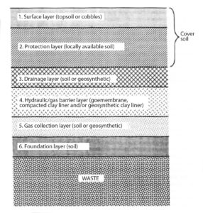
Koerner and Daniel (1997) describe each layer, its purpose, and counterpart the use of natural soils vis-à-vis geosynthetics. This particular cross section, with the barrier layer being a geomembrane over a compacted clay liner (i.e., a GM/CCL composite), is considered the “traditional” cover in this article.
Concerns regarding traditional final covers
There are many concerns over the use of a final cover as indicated in Figure 1 particularly when it is installed within one year after final waste placement due to its subsequent behavior.
Perhaps the major consideration is the large amount of settlement of MSW over time. See Figure 2 where settlement values, as a percentage of original waste thickness, can be 30% and greater.
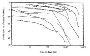
Even further, note that the settlement in several of the case histories is still ongoing.
In undergoing such settlement, natural soils—particularly compacted clay liners—will likely crack and lose their initially placed low permeability (see Heerten and Koerner, 2009, among others). The emergence of bioreactor landfilling (Reinhart and Townsend, 1998) only exacerbates such settlement with respect to both time and amount.
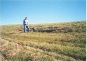
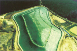
Accompanying such large landfill settlements is the possibility of differential settlement whereby localized depressions are formed. These will act as “bathtubs” and surface water will be captured and eventually diffuse through the barrier layer even if it is not breached. Figure 3 shows a localized landfill settlement depression.
Other adverse aspects of traditional landfill covers that can readily occur within the 30-year post-closure care period include:
- erosion of topsoil and some or all of the soil protection layer.
- gas bubbles (called “whales”) pushing the geomembrane barrier up through the overlying layers.
- veneer sliding of the cover soil above the lowest shear strength interface within the multilayered cross section.
- burrowing animals within the topsoil and protection soil thereby compromising performance of
the system. - trees and other major vegetation growing in the soil above the drainage layer with roots that penetrate it causing excessive clogging.
The net result of the current RCRA regulations as far as placement of traditional MSW landfill covers is concerned is a situation with numerous pitfalls and obstacles challenging its long-term efficiency within this initial 30-year time period. This, of course, says nothing about the costs involved, which is discussed later.
Exposed geomembrane landfill covers
In the 25 years since the RCRA regulations were promulgated by the U.S. Environmental Protection Agency (EPA) all geosynthetics, including geomembranes, have made great strides in their formulations and manufacturing. Issues such as degradation by chalking or powdering, as well as stress cracking, have been eliminated (or greatly mitigated) when selecting the proper resin and additive package; the latter consisting of processing stabilizers, long-term antioxidants, and carbon black or colorants. Geomembrane field problems have occurred, but when properly selected and formulated, an exposed lifetime of 30 years (even in hot climates) is achievable. To substantiate this statement, ongoing results of a seven-year laboratory study being conducted by GSI follow.
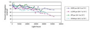
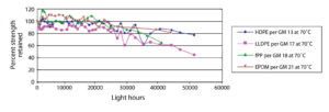
Figure 4 is a mosaic of four different resin types— HDPE = high-density polyethylene, LLDPE = linear low-density polyethylene, fPP = flexible polypropylene, EPDM = ethylene propylene diene monomer—that are being using in many exposed geomembrane applications (e.g., dams, reservoirs, canals, etc.). Figure 4a is the percentage strength retained from the original material; Figure 4b is the complementary percent elongation retained.
The exposure procedure for all materials is according to ASTM D7238 at 70°C. The subsequent tensile testing to obtain the numeric data is per D6693 for HDPE, LLDPE and fPP, and D882 for EPDM. The results are tabulated in Table 1.
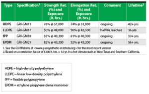
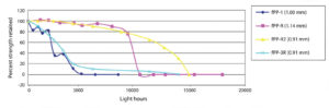
Note in Table 1 that a 50% reduction from the as-received material properties is considered the half-life and this value is used in the lifetime prediction. Only the LLDPE has reached this value currently although the EPDM is close. The correlation factor was based on four field failures (two in West Texas and two in Southern California) of fPP geomembranes that had archived samples. These samples were also tested per D7238 at 70°C until halflife and the number of light hours obtained accordingly (see Figure 5a).
This value compared to the actual field performance time resulted in a correlation factor of 1,200 light hours being equivalent to 1.0 year of service life in a hot climate (see Figure 5b).
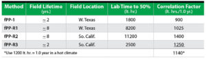
In essence, the laboratory incubation is providing an acceleration factor of 6.1 over field service time in these hot climates.
The point is that several geomembrane types can readily satisfy the 30-year time required for post-closure of landfills. In a less severe climate than Figure 5 indicates, the geomembranes evaluated can surpass 30 years. To the author, this data suggests that an exposed geomembrane is a viable option to a traditional one as indicated by the layered system shown in Figure 1.
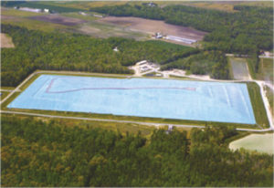
Figure 6 shows a number of exposed geomembrane covers that have been performing well over time. Perhaps the biggest issue over exposed geomembranes is their anchorage against wind uplift. This issue has been largely solved using parallel downslope anchor trenches as described by Hullings (2009).
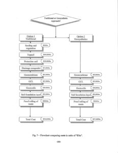
Cost comparison: traditional vs.exposed
When comparing a traditional landfill cover as indicated in Figure 1 to an exposed geomembrane cover as shown in Figure 6, the elimination of surface layer, protection layer, and drainage layer will obviously economically favor the exposed geomembrane solution.
That said, the exposed geomembrane solution will still require a gas collection layer and an underlying foundation layer. It will also require a thicker (hence, more robust) geomembrane and these considerations are reflected in the cost analysis to follow. A 1.0mm LLDPE was used for the traditional cover and a 1.5mm fPP/EPDM for the exposed.
In the following cost analysis, a landfill cover near Philadelphia, Pa., is envisioned. The estimated installed unit prices are current as of summer 2010 (see Table 2).
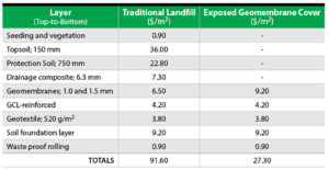
These unit prices are then extended to a hectare (Figure 7). As anticipated, the exposed geomembrane cover is only a fraction (30%) of the cost of a traditional final cover during the 30-year period envisioned. Of course, this leaves open the question of performance after 30 years.
If the traditional final cover and exposed geomembrane covers are both depreciated at this time, the cost comparison is valid. If, however, the traditional final cover is still functional, or is partially functioning and can be reasonably remediated, the cost comparison is invalid. In a converse sense, the large settlement of the waste mass at the end of this 30-year period (Figure 2) is recoverable for additional waste placement. This cannot be accomplished if a traditional final cover of the type shown in Figure 1 is deployed. In both of these issues it is fully realized that site-specific conditions prevail.
Carbon footprint: traditional vs. exposed
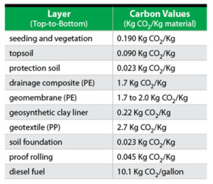
A flow chart containing each layer will be used to compare the carbon footprints of a traditional final cover and an exposed geomembrane cover. Data on CO2 values were obtained from the U.S. EPA (2005), the University of Bath (2008), and the German Institute for Energy Conservation (1999).
See Table 3—units are Kg CO2/Kg of specific materials as well as Kg CO2/gallon of diesel fuel for the transportation costs.
The flow chart of Figure 8 presents the calculated values of kilograms of CO2 liberated for the respective materials per square meter and then extended per hectare. Diesel fuel is based on truckloads of the various materials from their estimated sources to a hypothetical site in the Philadelphia, Pa., area.
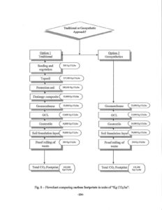
These two values (materials and transportation) are then added and transposed onto Figure 8 for each layer of material of the two respective alternatives and totaled. The CO2 footprint of the exposed geomembrane cover is only 20% of the traditional multilayered cover shown in Figure 1.
What happens after 30 years?
To use an exposed geomembrane cover for the 30-year post-closure care period, approval by the appropriate state environmental agency must be obtained.
A 2009 GSI survey queried the 50 American states with a response from 32 of them. Figure 9 shows information gained about the maximum time allowed before final cover is placed. It ranges from 30 to 360 days, with one state allowing 720 days.
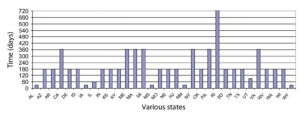
More significant in the context of an exposed geomembrane cover is whether it is even allowed. In this regard, state regulators gave the following responses: Yes–7, No–16, Conditionally–9, Undecided–18.
Other responses to various questions in the survey were as follows:
Regarding the necessity of an actual performance bond, 15 states required an insurance bond while 17 required that the owner must instead demonstrate financial assurance. The time duration for such bonds is the standard 30 years for 22 states. Two states require 40 years and eight require a bond for the post-closure period of undesignated duration. The amount of bond varies from state-to-state, but one state is specific at $100,000 per acre adjusted for inflation.
Regarding the situation of times beyond the initial 30-year post closure period, 16 states are beginning to address the issue and several have a draft policy or are considering time extensions. Comments such as “possibly indefinite,” until the waste is “stabilized,” or “as long as necessary” are also mentioned.
Summary and conclusions
The contrast of cost and carbon footprint of a multilayered final cover vs. an exposed geomembrane cover for closed MSW landfills is dramatic. Shown in this article, the values are as follows:
- The cost of an exposed geomembrane cover is 30% of the traditional cover.
- The CO2 footprint of an exposed geomembrane cover is 20% of the traditional cover.
These contrasts speak well for the initial 30-year post-closure care period, but they beg the question about an appropriate strategy for even longer time frames. This issue is clearly on the minds of the regulatory community and undoubtedly the landfill ownership community as well.
Perhaps it is time to begin to seriously explore the possible alternatives that lie ahead.
Bob Koerner is director emeritus of the Geosynthetic Institute, based in Folsom, Pa. He is a member of the Editorial Advisory Committee for Geosynthetics magazine.
Acknowledgements
This paper is made available through financial assistance of the members, affiliated members, and associate members of the Geosynthetic Institute (GSI). We sincerely thank them in this regard. See our website for their identification and contact persons.
References
ASTM D882 – Test Method for Tensile Properties of Thin Plastic Sheeting.
ASTM D6693 – Test Method for Determining Tensile Properties of Nonreinforced Polyethylene and Nonreinforced Flexible Polypropylene Geomembranes.
ASTM D7238 – Test Method for Effect of Exposure of Unreinforced Polyolefin Geomembranes to Fluorescent UV Condensation Apparatus.
Edgers, L., Noble, J. J., and Williams, E. (1990), “A Biologic Model for Long Term Settlement in Landfills,” Tufts University, Medford, Mass.
FFE Forschungsstelle für Energiewirtschaft der Gesellschaft für praktische Energiekunde e.V. (1999): Ganzheitliche Bilanzierung von Grundstoffen und Halbzeugen, Teil I Allgemeiner Teil,Teil II Baustoffe, Teil III Metalle, Teil IV Kunststoffe, München.
Gleason, M. H., Houlihan, M. F., and Giroud, J.-P. (1998), “An Exposed Geomembrane Cover System for a Landfill,” Proceedings 6th ICG Conference, Atlanta, Ga., IFAI Publication, pp. 211-213.
Heerten, G. and Koerner, R. M. (2008), “Cover Systems for Landfills and Brownfields,” Journal of Land Contamination and Reclamation, Vol. 16. No. 4,
London, England, pp. 343-356.
Hullings, D. E. (2009), “Exposed Geomembrane Cover Details,” Proceedings GRI-22 Conference, Salt Lake City, GSI Publication, Folsom, Pa., pp. 77-85.
Koerner, R. M. and Daniel, D. E. (1997), Final Covers for Solid Waste Landfills and Abandoned Dumps, ASCE Press, Reston, Virginia, 256 pgs.
Koerner, R. M. and Koerner, J. R. (2007), “GRI’s Second Worldwide Survey of Solid Waste Landfill Liner and Cover Systems,” GRI Report No. 34, GSI Publication, Folsom, Pa., 137 pgs.
König, D., Kockel, R., and Jessberger, H. L. (1996), “Zur Beurteilung der Standsicherhert und zur Prognose der Setzungen von Mischabfalldeponien,” Proc. 12th Nürnberg Deponieseminar, Vol. 75, Eigenverlag LGA, Nürnberg, Germany, pp. 95-117.
Reinhart, D. R. and Townsend, T. G. (1998), Landfill Bioreactor Design and Operation, Lewis Publishers,
Boca Raton, Fla., 189 pgs.
Spikula, D. (1996), “Subsidence Performance of Landfills: A 7-Year Review,” Proc. GRI-10 Conference on Field Performance of Geosynthetics and Geosynthetic Related Systems, GSI Publication, Folsom, Pa., pp. 237-244.
U. S. EPA (2005), “Emission Facts,” Office of Transportation and Air Quality, EPA 420-F-05-001, February.
University of Bath (2008), “Inventory of Carbon and Energy,” Version 1.6a, see www.carbonneutralfuel.co.uk