 TEXTILES.ORG

Moderated by George R. Koerner
Puncture after NDT
Q: I would like your opinion on the fate of punctures in the air channel leftover from nondestructive air channel tests (NDTs), specifically in regard to sealing the air channels to prevent leachate or water ingress. We are particularly concerned with this situation on a landfill cover should liquid freeze and expand in the air channel.
A: I hope this email finds you well. Thank you for your Techline question in regard to repair of NDT testing punctures.
Yes, is the answer. The puncture(s) in the air channel leftover from the NDT needle and unsealed end(s) need attention after the test. I have seen the following written into plans and specifications:
- Extrusion bead over needle hole and hot air weld (Leister) shut the far end after air release
- Patch area of NDT to isolate air channel from intrusion
- Cutoff end where NDT occurred and seam perimeter (i.e., linear low-density polyethylene [LLDPE] cover to high-density polyethylene [HDPE] liner) with an extrusion weld or solid wedge with “T” seams
In all cases the air channel is isolated to prevent liquid from entering it. Confirmation of these events is in the construction quality assurance (CQA) record as verification. Today, expert systems are even requiring photo documentation of the events surrounding this isolation.
Time between trial welds
Q: Is there a standard or guideline for how much time between trial welds during the course of a day is acceptable? We are working with an older CQA plan that states no more than four hours, which is shorter than the normal five hours the installer was expecting and that I’ve normally seen in other CQA plans.
A: In regard to a specific time between trial welds, we usually see it at five or six rather than four hours. This guidance can be found in the following two references:
Daniel, D. E., and Koerner, R. M. (2006). Waste containment facilities: Guidance for construction, quality assurance and quality control of liner and cover systems, 2nd ed., ASCE Press, New York.
Daniel, D. E., and Koerner, R. M. (1993). “Quality assurance and quality control for waste containment facilities,” US EPA Technical Guidance Document, EPA/600/R-93/182, Washington, DC, Office of R & D, Cooperative Agreement No. CR-815546-01-0.
Both documents state that trial welds are tested on-site two times a day: Once to start the day and then after the lunch break. Sure would hate to do trial welds for a second time in the morning an hour before lunch and then knock off. That stated, the site-specific CQA plan rules one behavior, and you need to follow it to the letter if you intend to get paid.
Membrane-encapsulated soil liners
Q: For expansive soil subgrade in pavement, can you suggest a geotextile that can function to control swelling and shrinkage in addition to reinforcement? Also, can you suggest a sensor that can capture the effectiveness of the geosynthetic being subjected to traffic in this application?
A: Please consult Robert M. Koerner’s Designing with Geosynthetics, 6th ed., Xlibris (2012) for a list of references on “membrane-encapsulated soil liners (MESLs)” that are used often in the southwestern part of the U.S. with great success. One can impregnate a needlepunched nonwoven geotextile with bitumen to establish an MESL rather than using a ready-made barrier or geomembrane.
In regard to a sensor that can monitor this situation, I would strongly recommend you read GRI-GS3 “Selecting In-Situ Monitoring Methods and Devices for the Evaluation of Geosynthetic Performance” and John Dunnicliff’s Geotechnical Instrumentation for Monitoring Field Performance, J. Wiley & Sons (1988). In addition, TenCate has a GeoDetect monitoring system based on geotextiles equipped with optical fibers, which may also be of interest and a great help to your effort.
Weld strength
Q: Our client is asking us if there is a formalized consensus when welding 60-mil (1.5-mm) high-density polyethylene (HDPE) geomembrane to 40-mil (1-mm) HDPE in regard to achieved target weld strength.
A: When welding 60-mil (1.5 mm) HDPE to 40-mil (1-mm) HDPE, one expects that only the weld strength of the 40-mil (1-mm) HDPE would be achieved, per GRI-GM19a: “Seam Strength and Related Properties of Thermally Bonded Homogeneous Polyolefin Geomembranes/Barriers.” I have witnessed this criterion in plans and specifications for many sites and believe that it is the norm in our industry for both fusion and extrusion seaming of HDPE geomembranes. Please note that this detail (i.e., situation) is called for on a regular basis whenever liner geomembrane (generally 60 mil [1.5 mm]) is welded to cap-cover geomembrane (generally 40 mil [1 mm]) to envelop the waste mass around the perimeter of a landfill cell.
Single- and multi-interface strength tests
Q: Can you give your opinion on the applicability of multilayer large-scale direct shear box testing compared to the results obtained from conventional tests described in ASTM D5321 and D6243?
A: Comparison of single- and multi-interface strength tests shows relatively good agreement, T. Stark and F. Niazi (2015) or Z. Yuan and R. Swan (2008). Single-interface test results appear to be a bit more conservative but have less uncertainty than multi-interface testing. There are several things you need to know about multi-interface testing:
- The procedure will appear in the next revision of ASTM D5321 in the appendix. This means that it is not required but an option for interface shear testing.
- Multi-interface testing requires special equipment and techniques to search out the weakest point within a landfill liner or cover system cross section.
- Multi-interface testing requires significantly more large-displacement strain to mobilize peak or residual stresses than in a single-interface test. The test apparatus (direct shear box) used for the test needs to be equipped for this extra displacement (i.e., well beyond 25% strain).
- The multi-interface testing setup is much more complicated, especially when dealing with different hydration and consolidation requirements of different soil types and/or geosynthetic clay liners (GCLs).
- The analysis of the failure mechanism involved with multi-interface tests requires experience with soil and geosynthetic forensics. Each side of each layer needs to be observed and evaluated for signs of deformation.
Given these criteria, it appears that we will be seeing more multi-interface testing, especially for projects designed in seismically active zones. This is a significant departure from the defendable boundary condition of forcing the Mohr-Coulomb failure envelopes between a single interface at a time for the two half-box conventional direct shear test.
Nominal value
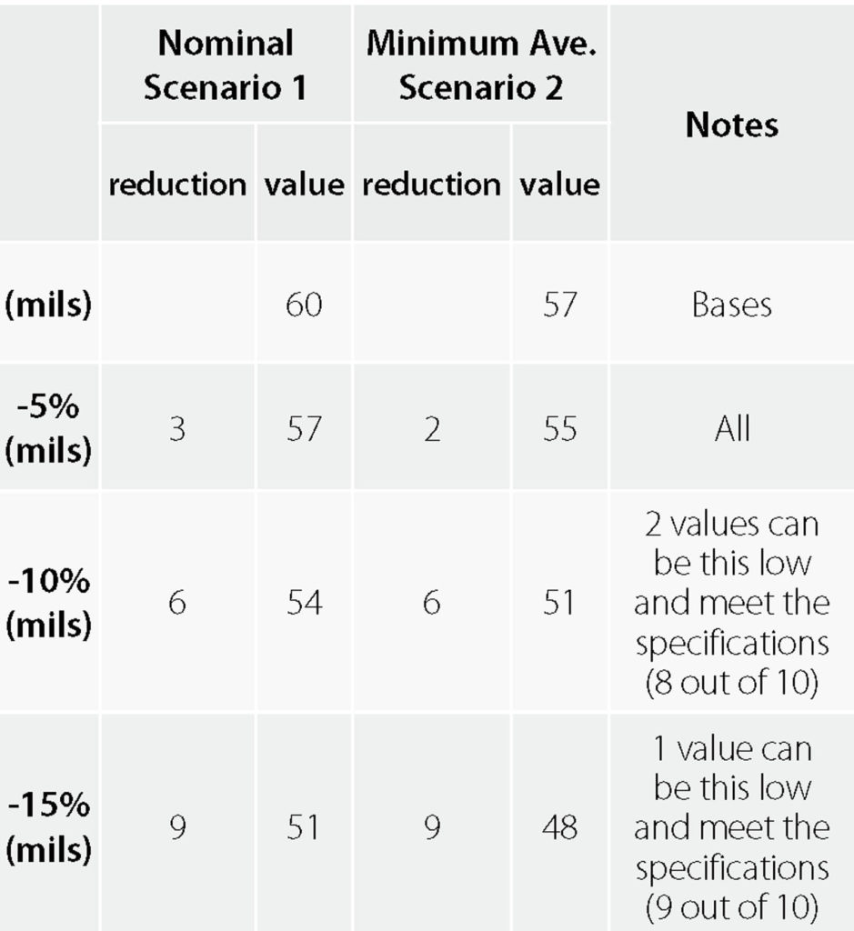
Q: Are the thickness specification values in GRI-GM13 and GRI-GM17 based on minimum average or nominal values? I will highlight my question around 60-mil (1.5-mm) textured geomembrane values and assume it would apply to the other thicknesses and materials in the specifications.
Scenario 1 is based on the percentages below the nominal value.
Scenario 2 is based on the percentages below the minimum average.
A: Scenario 1 is what the values in GRI-GM13 and GRI-GM17 specifications are based on. Percentages below the nominal value are represented by nom. -5% in Table 1. We will certainly highlight this in the GRI specifications in the very near future to avoid confusion going forward.
Membrane-encapsulated soil liners
Q: For expansive soil subgrade in pavement, can you suggest a geotextile that can function to control swelling and shrinkage in addition to reinforcement? Also, can you suggest a sensor that can capture the effectiveness of the geosynthetic being subjected to traffic in this application?
A: Please consult Robert M. Koerner’s Designing with Geosynthetics, 6th ed., Xlibris (2012) for a list of references on “membrane-encapsulated soil liners (MESLs)” that are used often in the southwestern part of the U.S. with great success. One can impregnate a needlepunched nonwoven geotextile with bitumen to establish an MESL rather than using a ready-made barrier or geomembrane.
In regard to a sensor that can monitor this situation, I would strongly recommend you read GRI-GS3 “Selecting In-Situ Monitoring Methods and Devices for the Evaluation of Geosynthetic Performance” and John Dunnicliff’s Geotechnical Instrumentation for Monitoring Field Performance, J. Wiley & Sons (1988). In addition, TenCate has a GeoDetect monitoring system based on geotextiles equipped with optical fibers, which may also be of interest and a great help to your effort.
Single- and multi-interface strength tests
Q: Can you give your opinion on the applicability of multilayer large-scale direct shear box testing compared to the results obtained from conventional tests described in ASTM D5321 and D6243?
A: Comparison of single- and multi-interface strength tests shows relatively good agreement, T. Stark and F. Niazi (2015) or Z. Yuan and R. Swan (2008). Single-interface test results appear to be a bit more conservative but have less uncertainty than multi-interface testing. There are several things you need to know about multi-interface testing:
The procedure will appear in the next revision of ASTM D5321 in the appendix. This means that it is not required but an option for interface shear testing.
Multi-interface testing requires special equipment and techniques to search out the weakest point within a landfill liner or cover system cross section.
Multi-interface testing requires significantly more large-displacement strain to mobilize peak or residual stresses than in a single-interface test. The test apparatus (direct shear box) used for the test needs to be equipped for this extra displacement (i.e., well beyond 25% strain).
The multi-interface testing setup is much more complicated, especially when dealing with different hydration and consolidation requirements of different soil types and/or geosynthetic clay liners (GCLs).
The analysis of the failure mechanism involved with multi-interface tests requires experience with soil and geosynthetic forensics. Each side of each layer needs to be observed and evaluated for signs of deformation.
Given these criteria, it appears that we will be seeing more multi-interface testing, especially for projects designed in seismically active zones. This is a significant departure from the defendable boundary condition of forcing the Mohr-Coulomb failure envelopes between a single interface at a time for the two half-box conventional direct shear test.