TEXTILES.ORG

Q: We are having issues related to obstructions in the reinforced zone of our mechanically stabilized earth (MSE) retaining walls. In the first case, there is a rock outcrop that is limiting the length of the geogrid reinforcement. In the second case, we have a drop-down inlet structure to divert stormwater, which is in the reinforced zone. Can you make suggestions on how to handle these situations?
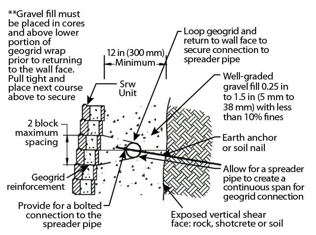
A: Nice to hear from you and please note that these situations are routinely handled with anchors, tie-rods and whalers (pipes). Your first situation has a National Concrete Masonry Association (NCMA) detail shown in Figure 3. The anchor can be soil nails, grouted earth anchors or even duckbill tendons (depending on the site geotechnics), all of which provide a bolted connection to the whaler. The geogrid is wrapped around the pipe in the “Z” direction and then connected to the wall face at different elevations by conventional means.
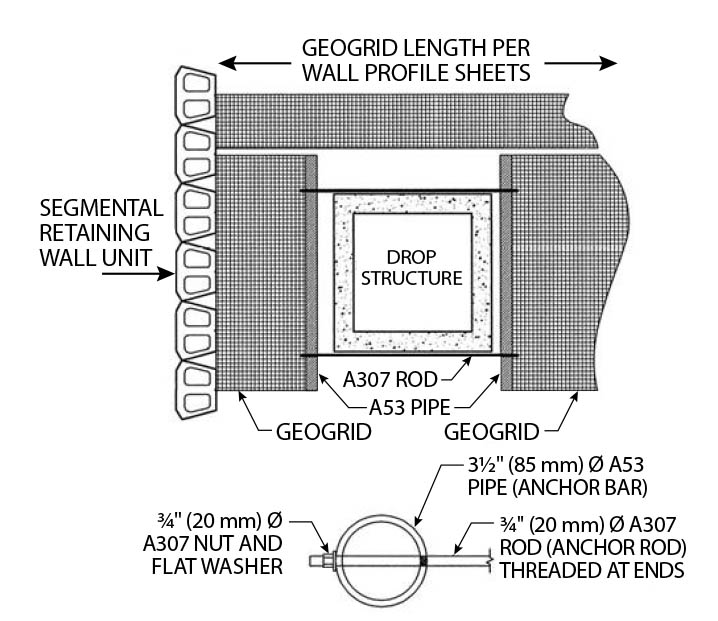
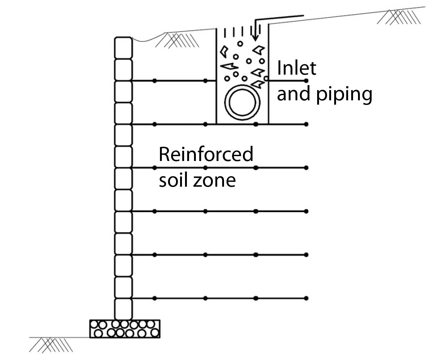
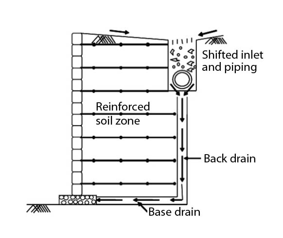
Your second situation is handled as shown in Figure 4. This detail was given to us by a clever engineer, Dean Sandri (TenCate), after the GRI-14 conference on “Hot Topics of Segmental Retaining Walls” in 2000. It uses similar technology as previously described. It needs to be said that this is a detail of last resort. We strongly recommend that all let-down structures be moved out of the reinforced zone, as shown in Figure 5a. One should anticipate some movement in most MSE walls. This movement results in leakage of drainage systems in the reinforced zone. The leakage creates excess pore water pressure in the reinforced backfill, which is not good long-term for wall stability. Whenever possible, drainage needs to be handled outside the reinforced zone, as shown in Figure 5b.