 TEXTILES.ORG

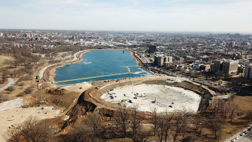
Druid Hill Reservoir is a one-billion-gallon (55-acre) potable water storage reservoir that supplies Baltimore, Md., and surrounding counties. Druid Hill Reservoir was constructed between 1863 and 1871 and is one of the largest earthen dammed lakes in North America. In 1971 it was named a National Historic Civil Engineering Landmark by the American Society of Civil Engineers.
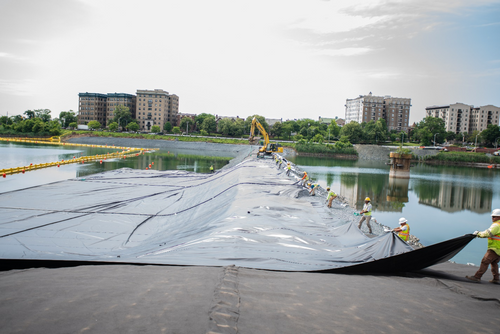
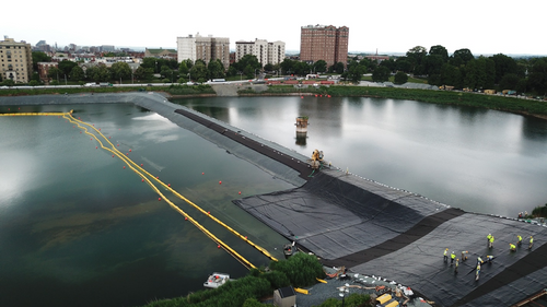
To drain one-half of the reservoir, while maintaining water on the other side, Hallaton lined a 1,200-foot (366-m) long rockfill berm to create a barrier system instead of driving steel sheetpiles as required in the original bid documents (Figure 1). The water-facing side of the rockfill berm was lined with an impermeable geomembrane so water could not flow from the water-filled side of the reservoir through the rockfill and into the other half while it was drained to construct underground storage tanks. First a geocomposite was placed on top of the rockfill to protect the reinforced geomembrane during deployment (Figure 2). Afterwards the factory-fabricated reinforced potable water grade geomembrane was installed over the geocomposite and floated out into the reservoir to cover the full length of the rockfill slope that was below water (Figure 3).

Challenging aspects of this project included:
The rock cofferdam varied in depth for 0 to 60 feet (0 to 18 m) over its length, so each factory-fabricated geomembrane panel varied in length and width to precisely cover the permeable cofferdam material to prevent leakage from the water to the dry side of the cofferdam.
Keeping the geomembrane afloat as it was incrementally being pulled out across the water and cofferdam was accomplished using floats.
The overall length of the cofferdam is 1,200 feet (366 m) but 300 feet (91 m) was along the southern side of the reservoir while 900 feet (274 m) was along the fairly straight cofferdam. The geomembrane for the 300-foot-long section was factory fabricated and then thermally welded in the field to the end of the 900-foot main section that was previously pulled into place
Sinking of the installed liner system needed to be controlled from the stone cofferdam. This required carefully timed and equally measured maneuvers on both sides to sink the liner system to the bottom of the reservoir and cofferdam. Following the successful sinking of the liner, divers were employed to ensure the geomembrane was in contact with the cofferdam to the reservoir bottom, so no leakage occurred.
After stone ballast was placed on top of the completed geomembrane, dewatering started on the western side where the new underground tanks would be constructed (Figure 4). The western side of the reservoir was completely dewatered to allow for the excavation and construction of the new underground water tanks to create a safe and protected treated water supply for Baltimore.
Lessons learned
Many lessons were learned from this project, including:
- Engineering smaller models and conducting many trial runs is beneficial in identifying potential issues when a project involves innovative design and construction techniques.
- There still may need to be some re-engineering on site to achieve best results.
- Good communication and collaboration between the engineer, general contractor and geosynthetics installer is important.
How the use of fabrication improved this project
Most of the geosynthetics were factory fabricated ahead of time, which increased the speed of the project because time was of the essence. Deploying geomembrane from the top of a cofferdam on one side, while keeping it straight, forward moving and floating was accomplished much easier using large factory fabricated geomembrane panels.
This case study first appeared on https://www.fabricatedgeomembrane.com. Used with permission.