 TEXTILES.ORG

By Javaid M. Alvi, Ph.D., and Jahangir J. Kabir, Ph.D., P.E
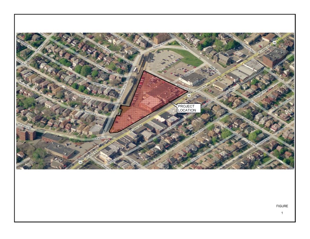
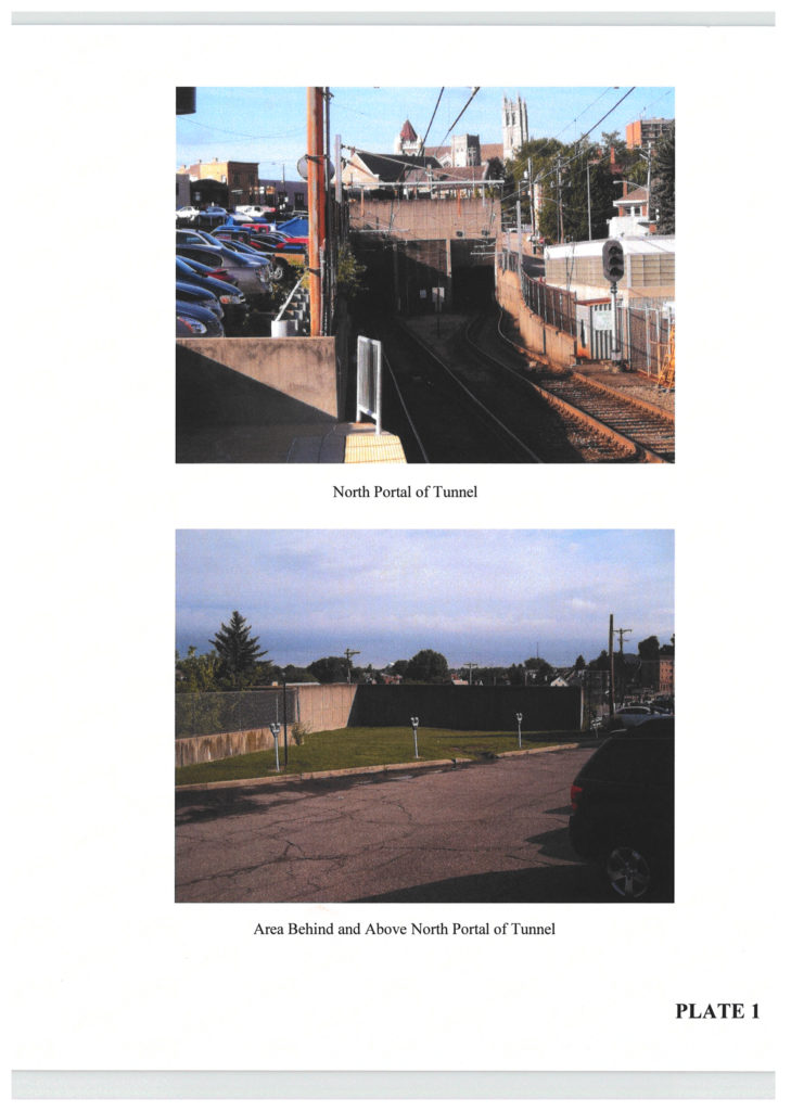
The project site is a triangular-shaped property located at the intersection of Raleigh Avenue and West Liberty Avenue in the Borough of Dormont, Allegheny County, Pa. (Figure 1). The site housed two Nissan buildings, one with a showroom at the top floor and the other a partially underground lower-level service area with side and rear entrances. Beyond the building the mildly sloping area was used for the parking lot that extended to the edge of the Mt. Lebanon tunnel section of the Allegheny County Port Authority Light Rail Transit (LRT) retaining wall. The area south of the existing buildings was a paved public parking lot that extended over the LRT tunnel that runs along Raleigh Avenue. The grade separation between the parking lot and Raleigh Avenue had been achieved by a concrete retaining wall constructed on top of the tunnel (Plate 1). The parking lot itself generally sloped from West Liberty Avenue to Raleigh Avenue with the highest elevation being at the intersection of the two roadways. The area immediately above the tunnel was relatively level and primarily covered with grass with a few parking spaces at its southwest corner. The retaining wall above the tunnel along Raleigh Avenue was three-to-eight feet high; the maximum height being at the north portal of the tunnel.
The existing highest elevation at the site is at USGS elevation 1,240 feet along West Liberty Avenue, and the lowest elevation is at USGS elevation 1,210 feet at the northern corner of the parking lot. The original site topography was dominated by a small gulley that had been altered by the cut-and-fill activities carried out during the construction of the tunnel for the transit line. A review of published geologic and mining maps of the area indicated that the project site is underlain by rocks belonging to Waynesburg Formation of the Dunkard Group of Pennsylvanian Age and consists of a sequence of limestone, claystone and sandstone with interbedded shale. The Pittsburgh coal seam, which has been extensively deep mined using the room-and-pillar method in the project area, is 310 feet below the ground surface. Generally, for a roof overburden thickness of 300 feet or more, the risk of structural damage to buildings due to any future mine collapse is slight to negligible based on a range of negligible, slight, moderate, great and severe. Consequently, mine stabilization to protect against and structural damage due to future mine subsidence was not a factor at this site.
Proposed development
The proposed $14 million development project included renovation and improvement of the two existing structures, namely 2,112-square-foot old service repair shop and 17,100-square-foot Nissan dealership showroom, construction of a new three-level space parking garage and a new 6,263-square-foot Infiniti dealership showroom on top of level 3 covering approximately 2.4 acres of property. The site is in an urban setting where land is of prime value. The project, therefore, was designed to maximize the available area by extending the building limit to the property lines as much as possible. This included the area above the LRT tunnel owned by Allegheny County Port Authority (ACPA).
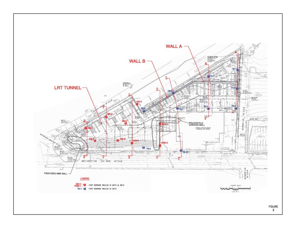
The old repair shop, which had experienced considerable damage due to differential settlement along its rear load-bearing wall, was to be incorporated into the new facility. The parking garage was to be constructed over the entire property outside the existing buildings with three levels of parking. The lowest parking level (Level 1) has a slightly sloping floor slab elevation of 1,210 feet, extending westward to within 10-feet distance of the LRT retaining wall. Level 2 (intermediate parking level) matched the existing service garage level at elevation 1,224 feet. The upper Level 3 parking coincided with the existing showroom level along Liberty Avenue at elevation 1,238 feet (Figures 2 and 3).
Level 1 and the eastern half of Level 2 were constructed at grade. The western half of Level 2 and the entire Level 3 consisted of overhead decks and were to be supported by structural slabs with isolated columns. The grade separation between Level 1 and Level 2 was to be achieved by a retaining wall. Both Level 2 and Level 3 wrapped around the existing building and extended southward into the area of the proposed new Infiniti showroom building. To maximize the garage capacity and land use, the western limit of garage extended over the existing LRT tunnel and next to the retaining wall forming the boat section of the tunnel where it is uncovered.
The new Infiniti showroom building is 58-feet wide and 83-feet long with 20 foot 48 foot additional area for service reception. The building is a one-story steel-frame structure with one level of underground parking. The new showroom building frame is supported by individual column foundations and the underground garage is supported by both load-bearing parameter walls and columns.
GeoMechanics Inc. was retained by the owner to perform the geotechnical investigation with the following three objectives in mind:
1) Develop the remedial method to restore the integrity of the existing repair shop.
2) Recommend foundation support systems for the parking garage and new Infiniti dealership showroom with associated geotechnical design parameters.
3) Develop special subgrade improvement/modifications method to minimize the impact of the construction on the LRT tunnel and retaining walls.
Subsurface conditions
Data collection
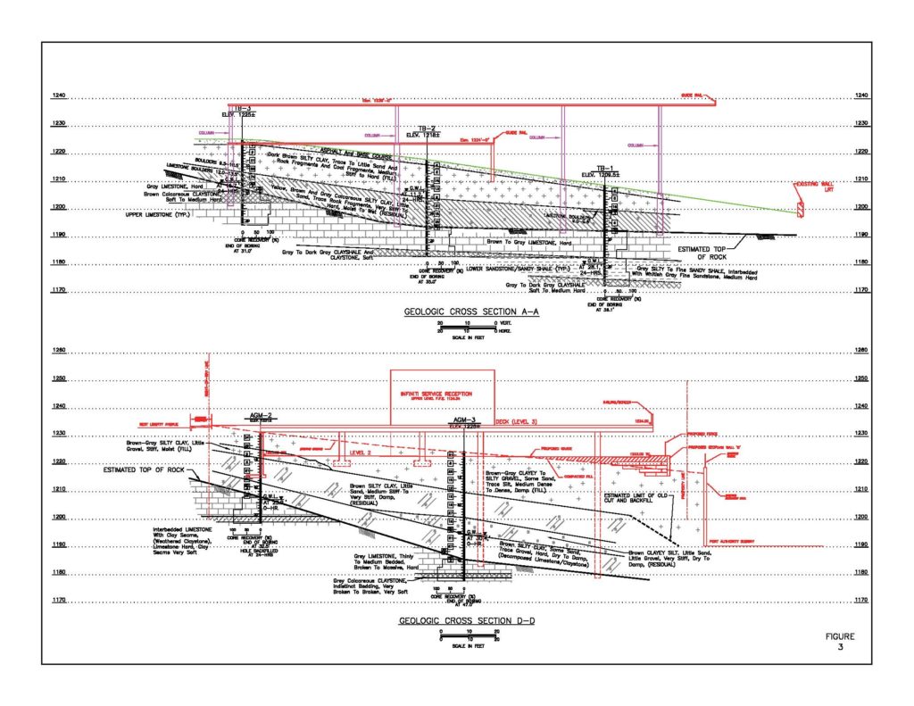
To achieve the above objectives, the subsurface geomaterials at the project site were delineated by conducting both a geotechnical exploration program and laboratory soil/rock testing. The subsurface exploration program was performed to determine the type, thickness and engineering characteristics of the soils; lithology and geomechanical properties of bedrock; and to ascertain the local groundwater conditions and also to delineate the top of the tunnel or footing of the existing parking lot retaining wall. The program consisted of drilling a total of 19 geotechnical borings spread across the project site, part of which is underlain by the existing Port Authority LRT tunnel. Three borings (GM-1 through GM-3) were located above the tunnel and the remaining 16 borings were outside the tunnel area. The boring locations are shown in Figure 2. The borings drilled outside the tunnel area were advanced through the soil zone by conducting standard penetration tests (ASTM D1586) and terminated after sampling several feet of bedrock using an NQ double-tube rigid-type core barrel; borings over the tunnel where terminated where refusal to split spoon sampler was encountered. These borings were drilled in three phases extending from year 2010 through year 2013 and were necessitated by the expansion of building structure along the south side of the existing building by acquiring the parking lot from the Borough of Dormont. A summary of the test boring records is presented in Table 1 and the relevant data including SPT N-values, percentage core recovery and rock quality designation (RQD), as well as stabilized groundwater level, are also shown on Generalized Geologic Cross-Sections Figures 3 and 4.

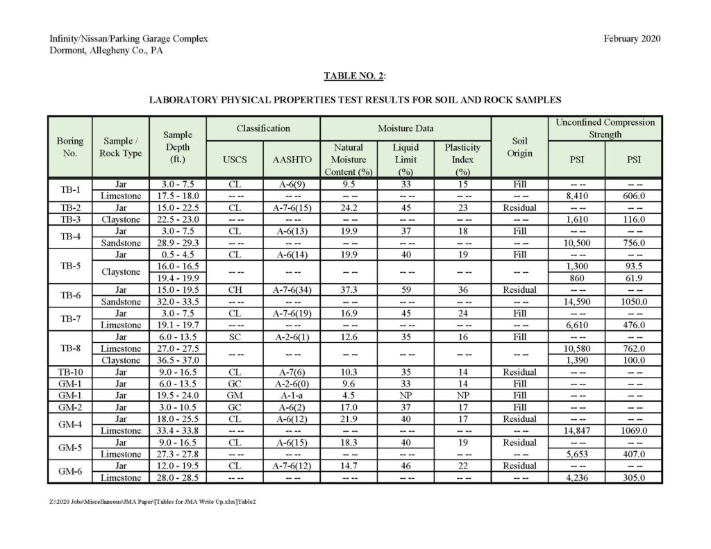
The laboratory testing program was limited to conducting index properties tests on representative soil samples and strength testing (uniaxial compression tests) on rock core samples. The results of soil tests are summarized in Table 2 and formed the basis of soil classification. The results of these tests were also used in conjunction with standard penetration test data (SPT N-values) to estimate shear strength and compressibility soil parameters needed for design. Uniaxial compression tests were conducted on 13 rock core samples obtained from the test borings. These tests were conducted on different rock types, namely limestone, claystone and sandstone. The data obtained from these tests was used to estimate bearing capacity and side-shear resistance of bedrock for foundation design.
Discussion of subsurface conditions
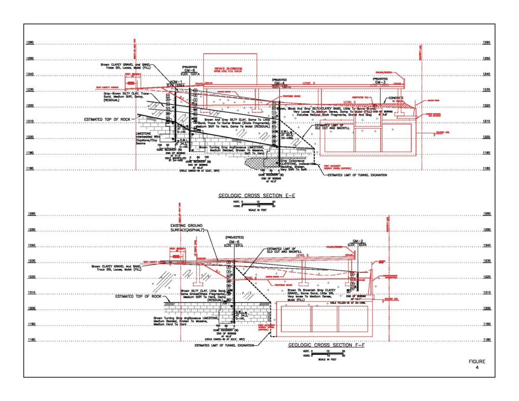
The data collected from the test borings and laboratory testing program has been used to construct generalized geologic cross sections across the project site, Figures 3 and 4. According to the geologic cross sections, the proposed project site was covered with a widely variable thickness of soil zone ranging from a minimum of 15 feet to a maximum of 40 feet. Apparently, a considerable amount of fill on top of residual soils had been placed in the past to develop the site grades at the time of the investigation.
At the northern part of the site, the fill had been placed to level the site for the showroom/service center building and gently sloping area below it that was used as a parking lot. The ground surface prior to the placement of fill at the northern part of the site sloped gently from a southeast to northwest direction. The thickness of fill varied from a minimum of 5 feet along West Liberty Avenue to a maximum of 23 feet near the LRT station wall. The fill material typically consisted of a medium stiff to very stiff silty clay matrix with variable amounts of sand and rock-size materials having occasional presence of concrete/brick fragments, slag, cinder and ash. There were also pockets of loose to medium dense granular material comprising of slag, brick/rock fragments, ash, etc.
The soil zone at the southern part of the project site also consisted of an upper layer of fill followed by residual soils; it increased varying from 25 to 40 feet. The fill was predominant at the west side of the site where the LRT tunnel is located. The original site topography was defined by a steeply northward sloping gully wall. During the construction of the tunnel, an up to 40-foot deep cut was made into the gully wall to reach the LRT grade. The limits of this cut are not known and were only estimated as portrayed on the idealized Geologic Cross Sections D-D, E-E and F-F (Figures 3 and 4). The cut removed all the soil cover and part of the underlying bedrock within the construction limits of the tunnel. After completion of the tunnel, the area was backfilled with structural fill and topped with common fill. As a result, the maximum thickness, up to 40 feet, was present along the sides of the tunnel.
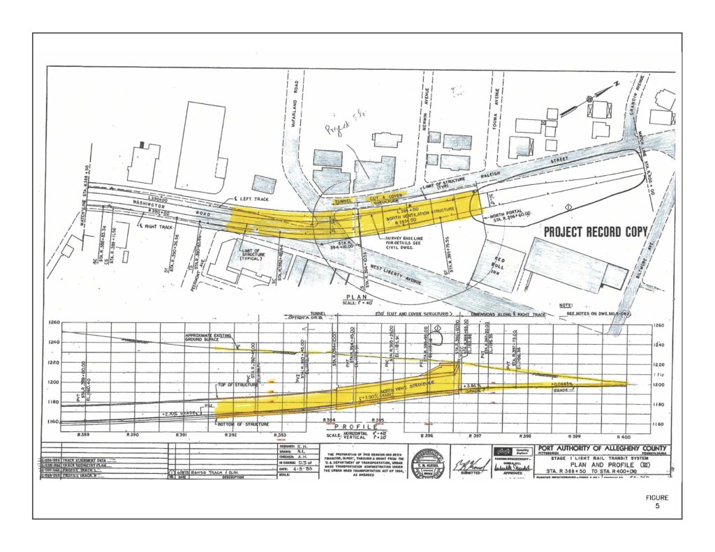
The thickness of fill above the tunnel varied from 25 feet near the corner of West Liberty Avenue and Raleigh Avenue and gradually decreased to zero at the north tunnel portal (Figure 5). The thickness of fill also decreased proceeding toward West Liberty Avenue where it was less than three feet in some areas. The structural fill consisting of free-draining granular material was limited to the area immediately around the tunnel. The upper fill layer was comprised of clayey gravel with sand as secondary constituent and had very-loose-to-medium dense relative density. The lower structural fill was described as silty gravel with some sand and typically had medium dense relative density; this provided an acceptable bearing medium.
Beyond the limits of the cut and below the surficial fill, residual soils formed most of the soil zone and were sampled in all borings with typical thicknesses of 5 to 12 feet. Their thickness was maximum, up to 21 to 24 feet, along West Liberty Avenue and gradually decreased proceeding toward the cut where it ends abruptly. The residual soils were essentially in-place badly weathered shale, claystone and limestone rocks. They were primarily fine-grained medium stiff to hard silty clay with pockets of medium-dense to dense rock fragments. The lower consistency was within the upper five feet. With increasing depth, the consistency of the soil increased as the intensity of weathering decreases and became hard as the bedrock was approached. Accordingly, the upper part of residual soils had low strength and high compressibility; whereas, the lower part had high strength and low compressibility, and provided good foundation bearing material. In general, the residual soils without improvement were considered poor foundation bearing material.
The “top of rock” below the soil cover was encountered at elevations varying from 1,204 to 1,195 feet. The bedrock primarily consists of interbedded limestone and calcareous claystone, silty to fine sandy shale and sandstone. The limestone was medium-bedded, massive and hard with broken soft seams, and sandstone was also blocky and medium hard. Therefore, these rocks were expected to provide high allowable bearing capacity. The claystone sampled across the project site was mostly broken and very soft to soft and was considered unsuitable bearing medium for supporting moderate to heavy structure loads. The bedrock, however, was too deep to be accessible for shallow foundations and could only be utilized if deep foundations were used. The most likely type of deep foundations was drilled-in, cast-in-place concrete caissons, which could be placed in high-strength limestone and sandstone rock units bedrock. However, because of the abundant presence of soft clay/claystone seams within the limestone bedrock and the soft shale interbeds within the sandstone, and the presence of softer claystone rock, six to eight feet below the bottom of caissons, the usable allowable bearing pressure had to be reduced considerably from 25 to 30 TSF to 10 to 12 TSF. The allowable bearing capacity of soft claystone is typically 3 TSF.
Perched groundwater was encountered either immediately above or below the bedrock in the test borings between 9-and-34-foot depth below the ground surface. The groundwater apparently migrates toward the LRT tunnel and retaining walls and drains out through the porous backfill placed along the tunnel and retaining walls. Therefore, groundwater remained below the bearing elevations of the shallow foundations and did not adversely impact their design and construction. For deep foundations, some seepage was encountered in the caisson holes and required dewatering.
Geotechnical design and construction issues
The primary geotechnical design issues at the project site and their discussion is presented below:
1) Remediation of settlement at existing service/repair shop
2) Foundation support system for garage and Infinity dealership showroom building
3) Interaction between the stresses imposed by the structure foundations and the existing LRT tunnel
4) Impact of stresses imposed by the parking garage foundations on the existing LRT retaining wall
5) Selection, design and construction of new earth retaining structures
Old service repair shop
The Cochran Nissan showroom and service building was a relatively old structure. The rear two-story part of the building was utilized for service and garage. The rear left corner extending up to the middle of the exterior load-bearing wall showed extensive differential settlement, tension cracks and outward rotation. Two test borings drilled along the rear wall indicated the presence of up to 10 feet of fill comprised of mostly fine-grained silty clay of primarily medium stiff consistency.
Several remedial methods including underpinning and hydraulically jacking the walls and in situ subgrade improvement using low-mobility compaction grouting were evaluated. Considering the building was in use, low-mobility compaction grouting was selected to stabilize the subgrade and raise the footings to close most of the cracks in the walls.
The subgrade improvement consisted of drilling an estimated 40 injection holes. The extent of the grouting was limited to 60 feet of the rear wall and 40 feet of the left wall proceeding from the rear left corner of the building. All grout holes were drilled along the outside of the building and at suitable angled to penetrate the soils below the footings. This was designed to help rotating the footings and the walls back toward their original alignment to some degree. The compaction grouting operation involved drilling or driving three-inch diameter steel pipe with a disposal tip to the desired depth below the fill layer where competent material was encountered. The pipe was drilled at an angle so that it could advance underneath the footing. A total of 21 primary holes located at a five-foot distance were drilled. Subsequently, each injection pipe was hooked on to the grout pump. The grout consisted of cement-sand of 2-to-3-inch slump and was pumped through the bottom of the pipe. After injection of the grout, the pipe was hydraulically lifted by two feet, and the process of grout injection was repeated. The grouting sequence required grout injection in every other boring located five feet apart. After completion of the initial grouting, the intermediate holes were grouted. Based on the grout take and the degree of wall movement, 14 secondary injection holes were drilled and grouted by splitting the distance between the primary holes. The grout was pumped under high pressure ranging from 60 to 30 PSI depending upon the grout intake. The highest pressure was used at the bottom of the holes and gradually decreased as the depth of overburden decreased. The grout intake was controlled by the following:
· The grouting was stopped once the refusal was met.
· The wall and footing were raised to the desired level.
· The ground around the injection hole started to heave.
· Predetermined grout intake had been pumped.
The movement of footing and wall was monitored by placing telltales on the wall and by observing its movement with a level.
All drilling and grouting was performed by GeoMechanics Inc. using its in-house equipment and personnel. The grout injection holes were drilled using CME-45 skid rig that was capable of drilling angle holes extending below the footings. Mixing and injection of grout was accomplished using the Powercreter Magnum pump manufactured by Allentown Equipment, a division of Putzmeister. The injection pressure typically ranged between 200 and 50 PSI. The depths of the injection holes varied between 13 and 17 feet. The grout take ranged between 0.15 to 2.10 cubic yards per hole resulting in a total of 30 cubic yards of grout.
Selection of foundation support systems
The existing buildings were supported by shallow foundations (continuous and spread footings). Therefore, the initial effort was to concentrate on using similar footings to support the new structure. The anticipated column loads of the addition varied from 25 to 119 kips, which are not excessively high, and foundation bearing medium for shallow foundations varied from relatively competent fill to residual soils to very competent bedrock. Therefore, it was reasoned that with proper subgrade improvement, shallow foundation could be used. The possible methods of ground improvement considered included conventional “soil exchange” method, rammed aggregate piers (RAP) and controlled modulus columns (CMCs). However, the site grading needed to extend the second level of parking garage to the property line along LRT would have resulted in applying additional loads on the tunnel wall. To avoid this, it was decided to use deep foundation (drilled concrete shafts) placed in bedrock below the foundation of the tunnel wall. Deep foundations for the columns located on top of the tunnel, however, could not be supported by deep foundation. It was also suggested to use soldier beam-concrete lagging wall along the tunnel wall to accommodate the additional fill needed to reach the second level of garage with floor slab at grade. Proceeding away from the LRT retaining wall, deep foundations were utilized only where the garage column loads were heavier.
Where bedrock, residual soils or compacted structural fill were present at shallower and readily accessible depths, shallow foundations were used. Foundation placed in soils, however, required “soil exchange” method for subgrade improvement.
The varying subsurface conditions across the new structure and the site constraints along the LRT necessitated the use of combined shallow and deep foundations with a construction joint separating the two sections, Area A and Area B, of the garage. Shallow foundations albeit with subgrade improvement using soil exchange method were limited to Area B; at Area A, drilled-in, cast-in-place concrete shafts socketed into claystone bedrock using an allowable bearing of 3 TSF were employed claystone bedrock was acceptable foundation bearing medium as the columns loads were not excessively high.
Interaction between proposed parking structure and LRT tunnel
The parking garage was intended to occupy the entire project area with Level 3 extending above the tunnel. The site constraints and the width of the tunnel (55 feet) would not allow spanning of the parking deck over the tunnel using deep foundations bearing in bedrock below the tunnel bottom. As a result, shallow foundations bearing in the soil mantle above the tunnel seemed to be the logical choice to support the structure. According to the loading information provided by the garage designer, the proposed maximum column and wall loads were 120 kips and 6 kips, respectively, which were not excessively high and could be supported using shallow foundations bearing in existing granular soils, which when properly compacted could provide 2 KSF net allowable bearing capacity to design economically sized footings. However, the impact of foundation stresses on the tunnel roof depended considerably on the depth of tunnel roof below the footings. To evaluate this impact, it was necessary to understand the existing tunnel configuration and profile. The section of the Mt. Lebanon LRT tunnel on the site from the intersection of West Liberty Avenue (SR19), McFarland Road and Raleigh Avenue approximate Station 393+50 to the North Portal Station 396+65, is described as follows:
· Station 393+50 to Station 394+10: This section of the tunnel is comprised of two separate excavated openings 18 feet in diameter separated by an unexcavated area of 15 feet. Total width of the affected excavation for the tunnel is 55 feet. Typical tunnel support includes drilled reinforcing dowels attached to steel I beams to support the rock excavation. The rock face and supports are then covered with multiple layers of wire-mesh-reinforced shotcrete to provide the lining of the tunnel. Average bottom and top elevation of the tunnel in this section is USGS elevation 1,170 feet to 1,173 and elevation 1,190 to 1,193 feet, respectively. The grade of the tunnel in this interval rises toward the north at 7.5%.
- Station 394+00 to Station 396+60 (North Portal): This section of the tunnel was built by the cut-and-cover construction method. The tunnel is comprised of a single reinforced concrete box structure with three cells approximately 15 feet square separated by a thin concrete wall. The outer two cells contain the tracks for the LRT. The interior cell houses electrical and ventilation equipment. Total width of the composite tunnel is approximately 55 feet. Bottom elevation of the tunnel at Station 394+10 is USGS elevation 1,173 feet and top elevation of the tunnel is elevation 1,195 feet, with upward grade of 7.5% proceeding toward the north. Bottom elevation of the tunnel at Station 396+60 is USGS elevation 1,193 feet and top elevation of the retaining wall at the north portal of the tunnel is elevation 1,220 feet. Fill material above the cut-and-cover sections varies from 40 feet at Station 394+00 and to 0 feet at Station 396+60.
The plan and centerline profile of the tunnel in the project area is shown on Figure 5, which was part of the Contract No. CA-260 for Stage I Light Rail Transit System, Port Authority of Allegheny County (1969 and 1984).
Prior to the performance of stress analysis, the following two adjustments in the foundation locations were considered:
1) The orientation of the column footing needed to be rotated so that they are parallel with the LRT tunnel to avoid interferences.
2) The footing located above “Area 2” needed to be lowered so that they are 2.5 feet above the top of the tunnel roof. The footings needed to be lowered to minimize the effects of lateral loads on the side wall of the center ventilation shaft. The three columns located adjacent to the east (inbound) wall of the tunnel were founded below the tunnel to minimize the lateral load applied to the side wall of the existing tunnel.
For the preliminary analysis, uniform loading was calculated based on the depth of the tunnel roof with relation to the proposed finished ground, preliminary building loads and live load surcharge. The preliminary analysis determined that several sections of the tunnel roof may not be “sufficient to support the additional load from the proposed structure.” Subsequently, ms consultants inc. was retained to perform a refined load effect study of the Mount Lebanon/Dormont LRT Tunnel. Their analysis utilized revised column locations and revised foundation loads supplied by the project structural engineer.
The refined load effect study of the LRT tunnel was performed at the following analysis points (as identified in the preliminary analysis):
· Area 2
· Area 4
· Area 5@S2
· Area 5@S3
· Area 6@S3
· Area 6@S4
For locations of areas, see Figures 6a and 6b.
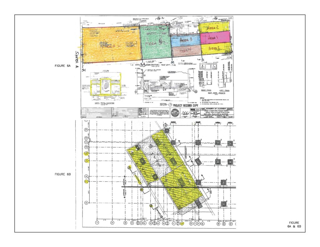
Note: In Area 1 or Area 3, the originally proposed column locations were altered to avoid applying load to these areas.
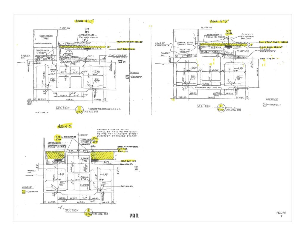
Area 2 and Area 4 of the LRT tunnel were analyzed comparing the existing loading condition to the proposed loading condition, and it was determined that the new loading conditions would exceed the existing loading conditions at some parts of the tunnel. To compensate for the increased loading, the soil exchange method was proposed. This involved removal of some of the existing soil and replacement with light-weight closed-cell expanded polyester (EPS) geofoam with 1.35 PCF density and compressive resistance of 7.3 PSI to 1 percent deformation of the geofoam so that the proposed total load above the LRT tunnel would be equal or less than the existing total load. The extent of this procedure along the length of the tunnel is shown in Figure 7. Due to the elevation of the proposed column footings with respect to the top of the LRT tunnel, partial-frame analyses were performed in these areas to determine the effects of the more concentrated load distribution from the proposed columns. The existing and proposed moments and shears were compared, and member’s capacities and performance ratios were determined for all members where increases in proposed moments and shears were anticipated.
Area 5@S2, Area 5@S3, Area 6@S3 and Area 6@S4 of the LRT tunnel were analyzed comparing the existing loading condition to the proposed loading condition. For these areas, the proposed total load above the LRT tunnel was less than the existing total load due to the lowering of the proposed finished grade that would remove some of the existing soils. Since the clearance between the LRT tunnel and the bottom of column footing elevations was greater than nine feet, the distribution of load from the footings was similar to uniform distributed loads. As the proposed uniform loads were lower than the existing uniform loads in these locations, partial-frame analysis was not warranted for these areas. These results indicated that by replacing existing soil with lightweight geofoam, the LRT runnel could safely accommodate the load effects associated with the proposed Infiniti building parking deck.
Interaction between new retaining walls and LRT retaining wall
Several retaining walls were needed to achieve the grade separation of the parking garage. All except one were located at a sufficient distance away from the LRT structure and were designed either as mechanically stabilized earth (MSE) walls or soldier-beam concrete lagging walls. The wall adjacent to the east retaining wall of the boat section of the LRT tunnel was needed to raise the ground surface to elevation 1,218 feet to create additional area for at-grade parking. Since this wall was designed to retain the new fill, the MSE wall was deemed to be the most cost effective. However, the soil fill would have imposed additional vertical and lateral stresses on the existing LRT tunnel walls and footings. Initially, a soldier beam-concrete lagging wall that would have eliminated the additional stresses on the LRT tunnel wall was considered but found to be too expensive. Consequently, an alternative solution using lightweight material for backfill in the retained section of the MSE wall was considered. Several lightweight materials that would have both reduced the stresses on the tunnel wall and provided the needed strength to support the garage floor were considered; these included foamed concrete, lightweight flowable material and EPS geofoam. Based on the unit density of the backfill material, site constraints, construction schedule and comparative costs, Insulfoam GF (geofoam) was deemed the most suitable backfill material in the reinforced zone behind the wall.
Proscope Landscape Supply, a specialty contractor for geogrid-reinforced walls, was retained to design and construct the two major MSE walls using both the conventional soils at the wall, which is away from the tunnel (Wall A), and geofoam for the reinforced zone for the wall adjacent to the Port Authority tunnel wall (Wall B). Engineered Earth Solutions Inc. and Insulation Foam were, in turn, retained by Proscope Landscape Supply to design and install the retaining structures. Typical cross sections for Walls A and B are shown in Figures 8 and 9.
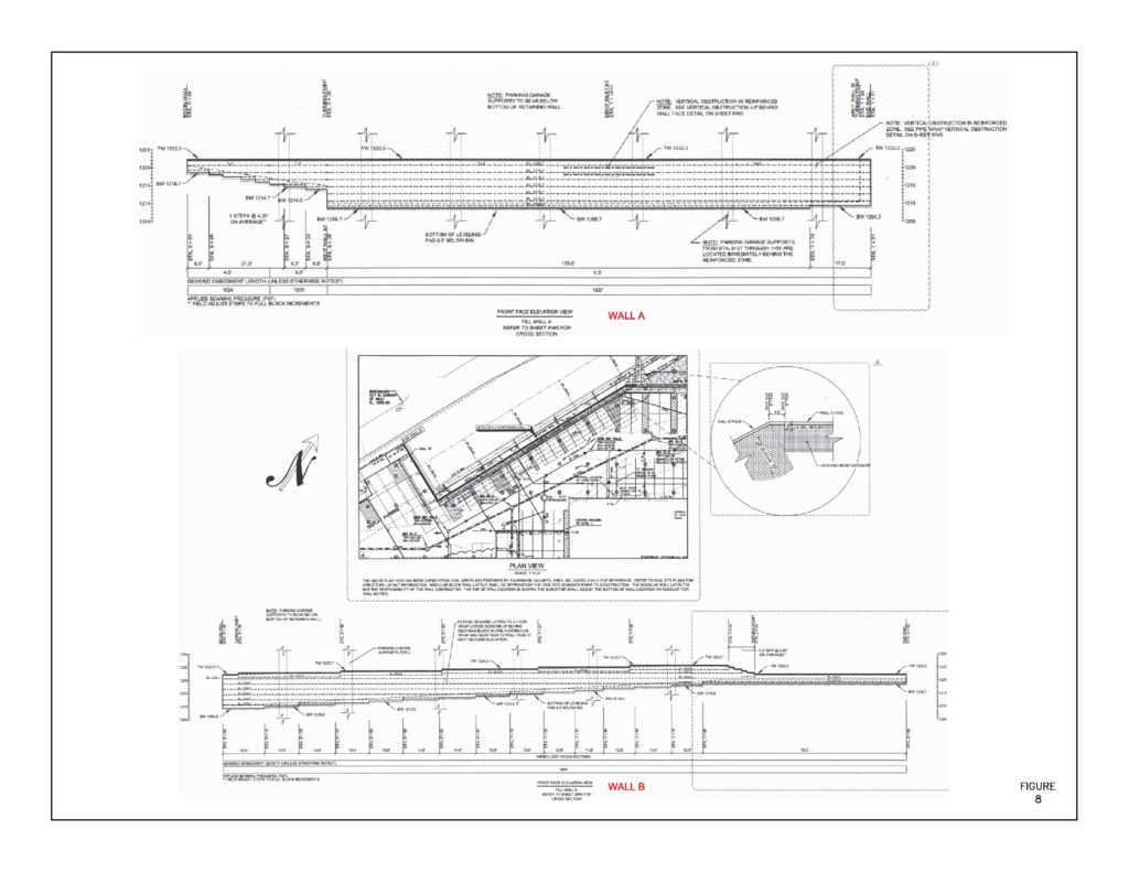
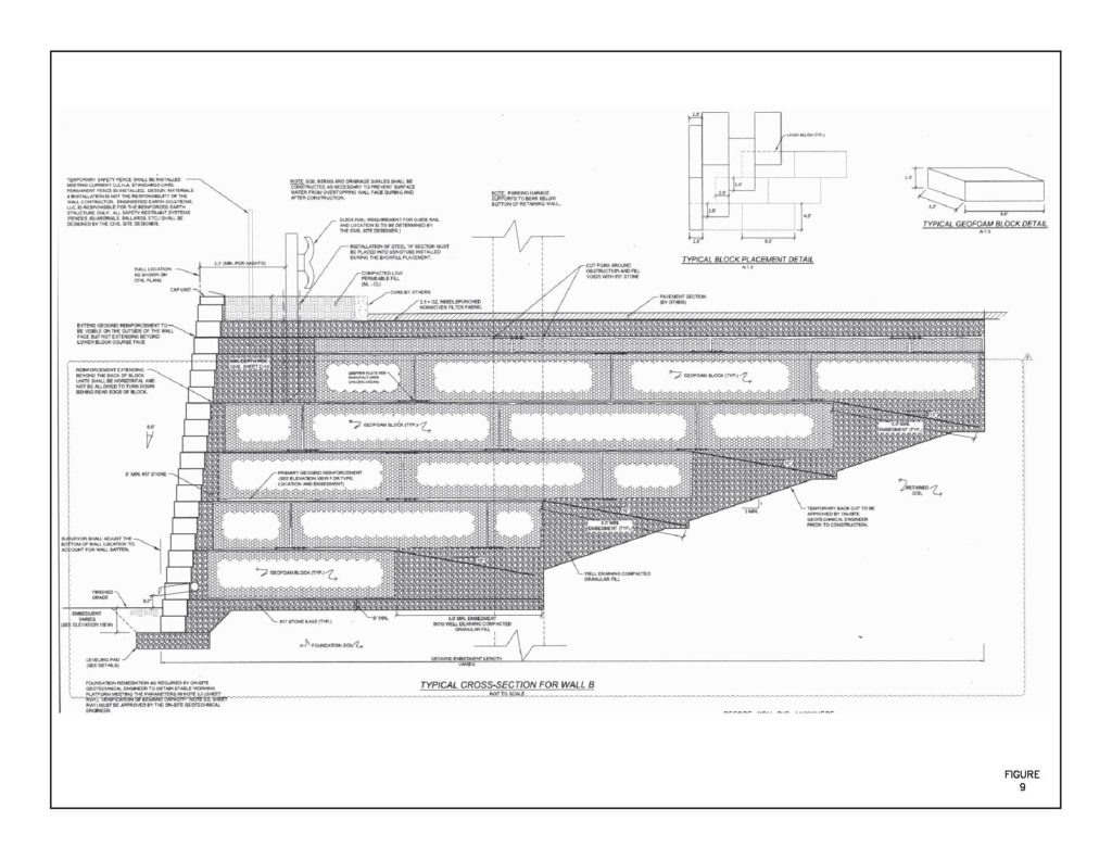
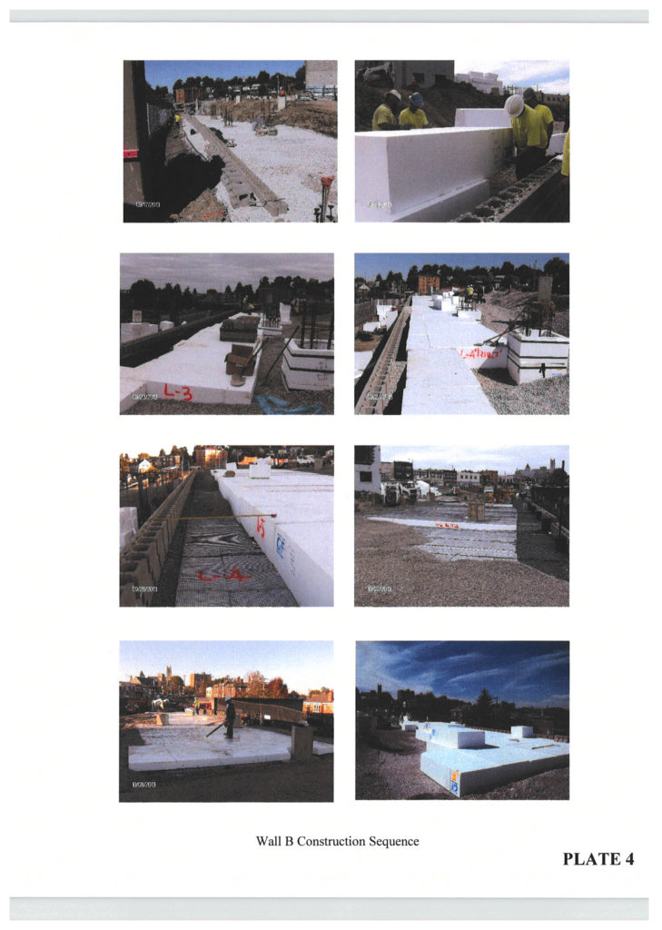
The length of MSE Wall B was 262 lineal feet with a maximum height of 13.67 feet at Station 0+06 to Station 0+83, resulting in 2,296 square feet. Within the highest section of MSE Wall B, seven layers of geofoam were constructed and five layers of Strata geogrid reinforcement was installed. A minimum of one foot of AASHTO No. 57 sized crushed limestone select fill was placed and compacted between backface of Keystone Compac III and geofoam lightweight backfill. In addition, a typical six feet of AASHTO No. 57 sized crushed limestone was also placed and compacted in 8-inch loose lifts behind the geofoam and before the retained earthen cut face. On top of the geofoam was placed and compacted a minimum one-foot layer of AASHTO No. 57 crushed limestone aggregate, which was covered with a nonwoven filter fabric topped by the pavement components.
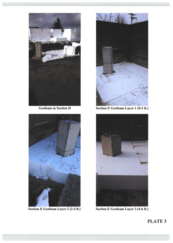
Insulfoam GF GFEPS22 meeting ASTM D6817 “Standard Specification for Rigid Cellular Polystyrene Geofoam” was used. A total of 400 flat blocks of 48-inch 96-inch size resulting in 790.91 cubic yards were used. Sixty-eight blocks were eight inches thick, 63 were 16 inches thick and the remaining 269 blocks were 24 inches thick. A typical detail for an MSE wall with geofoam backfill is shown in Figure 9. These geofoam blocks were installed in an interlocking pattern (i.e., masonry brick) to eliminate a structural joint and to provide a more stabilized “structural” fill. Layers of Tensar geotextile grid installed within granular backfill was utilized to improve lateral and bearing capacities of the parking area slab on grade. Wall B was completed in about 10 working days. For progress of wall installation, refer to Plates 3 and 4. The cost of approximately 2,296 square face feet of geofoam wall was approximately $128,000 or $56.80/square foot. This included the material cost of keystone units, geogrid and geofoam ($106,334) delivered to the site. The cost, however, did not include the cost of subgrade preparation that included some undercutting and backfilling to the limits of geofoam wall that was performed by the site-grading contractor.
Conclusions
Construction of a new Infiniti showroom, improvement and incorporation of the old Nissan showroom and service building into a new structure with three levels of parking garage adjacent to and above the LRT tunnel required several challenges and innovative solutions. The distressed part of the old Nissan service building needed compaction grouting to close the building cracks and stabilize the subgrade. Removal of existing heavier soils on top of the tunnel roof and replacement with lighter weight geofoam proved to be the successful option in reducing the loads on top of the tunnel to accommodate safely the additional stresses imposed by the column footings of the garage. Geofoam also came to the rescue by minimizing the lateral stresses on the tunnel walls and allowing the use of less-expensive MSE wall to raise the floor slab grade adjacent to the wall instead of employing a more expansive beam-and-lagging wall. Use of geofoam also helped with the construction schedule as it took only 15 working days to install the geofoam above the tunnel and for the MSE retaining wall.
References
“Cochran Infiniti building parking deck over light rail transit system: LRT tunnel load effect study.” (2003). ms consultants inc., Nov. 23.
“Port Authority of Allegheny County, Stage 1 light rail transit system, Plan and profile (III).” (1993). Parsons Brinkerhoff, Gibbs and Hills, March 29.