 TEXTILES.ORG

By Bryan C. Gee, Eric Klein and William T. Maier
The Maryland Transportation Authority (MDTA) is implementing a multiyear, multiphase project to add express toll lanes (ETLs) to Interstate 95. The ETLs are providing significant congestion relief in one of the most heavily trafficked corridors in the United States. The major modification to I-95 consists of adding two ETLs in each direction. The eight general purpose lanes (GPLs) will be maintained. The ETLs are located between the northbound and southbound GPLs and separated from the GPLs by a concrete barrier. The ETLs were designed for a 25-year life and 9.5 million 18-kip (80-kN) equivalent single axle loads (ESALs). The areas where the very soft soils were encountered were northbound ETLs just north of the I-95 bridge over White Marsh Run and south of the Maryland 43 bridge over I-95.
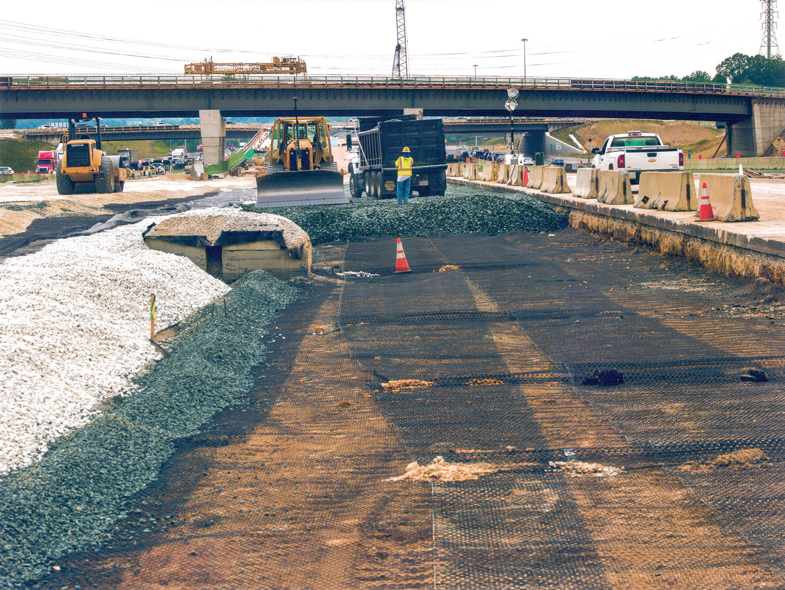
Some areas with very low California Bearing Ratio (CBR) values were encountered during the design phase. The contractor was given the choice of using a lime/fly-ash mixture or to undercut and replace with a separation fabric and stone (Figure 1). Where soft soils had been encountered previously, they were thin enough that the contractor simply removed the soft soils and replaced them with a separation fabric and stone.
Site conditions
The soils in these areas were weak, saturated clays and silts with very low shear strength. CBR values were well below 1%, and the poor soils extended to depths of at least 6 feet (1.8 m). Using a calibrated drop hammer penetrometer, the CBR values were found to range from 0.1% to 0.5%. These poor soils were first encountered in March 2014, but they were thin enough that they were simply undercut. As the project advanced the poor soils got deeper, and test pits determined that the undercut would be significant. The roadway was to open in fall 2014. To undercut and replace or to mobilize the lime/fly-ash mixing equipment would have delayed the opening of the toll road.
The logistics of addressing the problem were equally challenging. Because the construction was occurring between the existing northbound GPLs and northbound ETL exit ramps of a major interstate, any material that would be required to enter or leave the site would do so through limited access points. Depth of excavation was also an issue, as the northbound exit ramps, to the west of the northbound ETLs, were supported on mechanically stabilized earth (MSE) walls about 25-feet (7.6-m) high. There were active GPLs immediately to the east of the northbound ETL. Even though the active traffic lanes were separated from the work zone by a concrete barrier, if the depth of undercutting was too deep, it could undermine the MSE and the active travel lanes, therefore, requiring a support of excavation (SOE). Design and construction of this would have delayed the opening of the highway and increased the cost. Further, space to operate equipment was limited, and any significant excavation would have had to consider the impact on the existing roadway just a few feet away. The soft subgrade was encountered only a few months prior to the scheduled opening of the toll lanes and a delay would have been costly.
Solution development
The contractor approached MDTA to determine a solution. The initial proposed option was to remove and dispose of 6 to 8 feet (1.8 to 2.4 m) of unsuitable material and replace it with suitable fill. While this approach would have resulted in an acceptable surface for construction, its impact on the project would have been extremely problematic due to the logistical and scheduling challenges noted previously. After evaluating this option, the contractor and MDTA concluded that the impact on the project schedule would be so severe that a different approach was needed.
The contractor then approached RK&K, the designer of record, and Tensar International Corp. to see if a solution could be developed that would keep the project on track. Together, the team evaluated the site conditions and developed an option that used a mechanically stabilized aggregate layer (MSL) to create a stable surface above the unsuitable material while requiring greatly reduced soil excavation and disposal.
The design was developed based on the Giroud-Han method for unpaved roads. This was suitable for the contractor’s haul road. It should be noted that while Giroud-Han served as a basis for the design, the final application was not an unpaved road subject to channelized traffic, for which the method is intended. However, Giroud-Han is the most rigorous and widely accepted method for designing gravel-surfaced roads over soft subgrades, so there is a large body of experience with conditions that are like those encountered in this case. Therefore, Giroud-Han can be effectively used to estimate thickness requirements as an initial step in the design.
Extensive field experience has shown that a Giroud-Han design based on a typical scenario (20-kip [89-kN] axle load, 100-psi [689-kPa] tire pressure, 1,200 passes, 1.5 inches [38 mm] max rut depth) consistently results in an improved subgrade surface with a CBR of 6% or greater. Based on this experience, a preliminary cross section can be developed. Since field conditions and constructibility issues not considered in the Giroud-Han method can affect performance, field testing is often used for design verification, depending on how critical subgrade strength is for the final design.
The highway pavement design used SpectraPave software. This application uses the empirically based 1993 American Association of State Highway and Transportation Officials (AASHTO) Guide for Design of Pavement Structures and enhanced layer coefficients to account for the benefits of the geogrid, and complies with AASHTO R-50, Standard Practice for Geosynthetic Reinforcement of the Aggregate Base Course of Flexible Pavement Structures. The coefficients used in this application are based on laboratory and field testing of these specific geogrids and should not be used with other geogrids (Applied Research Associates Inc. and Ryan R. Berg Associates 2013).
Once a preliminary design for the haul road was developed, two test strips were built: one using two 12-inch (305-mm) layers graded aggregate base (GAB) with two layers of multiaxial geogrid, and the other using one 24-inch (610-mm) layer of No. 2 stones and one layer of multiaxial geogrid. The No. 2 stone was choked with GAB to improve the rideability. The test strips were trafficked with a fully loaded tandem dump truck (gross vehicle weight 50,000 to 60,000 pounds [23,000 kg to 27,000 kg]) to observe rutting behavior.
The ruts observed in the first test strip were approximately 3.5 inches (89 mm) deep after fewer than 10 passes. The second test strip developed very shallow ruts (0.5 inch [13 mm] or less). This experience with the haul road was then incorporated into the final pavement design.
Once the initial estimate of required thickness for the final pavement was established, the team considered other site conditions that might affect the success of the design and adjusted accordingly. Two primary concerns were addressed: variability in the strength of subgrade soils across the project and the potential effects of groundwater and drainage. Constructibility of the pavement drainage system and how the drains tied into the already-constructed storm drain system were also considered.
To address the variability in soil conditions, the primary concern was to ensure that the MSL would maintain maximum stiffness so that the surface would remain stable. Stiffness in the layer is established by the confinement and interlock of the particles of granular fill. Prior research has demonstrated that the compacted granular fill above a geogrid has both fully confined and partially confined zones, so as thicker granular layers are used, confinement can be enhanced using additional layers of geogrid. In general, layers of multiaxial geogrid that are spaced at approximately 12 inches (305 mm) within the MSL are adequate to maintain full confinement. The test strips indicated that only one layer of geogrid with the No. 2 stone provided adequate support; therefore, in this case, it was decided that the design would use one layer of geogrid in the 24-inch (610-mm) thick MSL. As this might not be adequate to provide support for the highway design ESALs, a second layer was located at the top of the MSL/haul road and the pavement section. The multiaxial geogrid selected had high flexural stiffness to provide the most stable surface possible for placing the initial layer of fill over the extremely soft soils below.
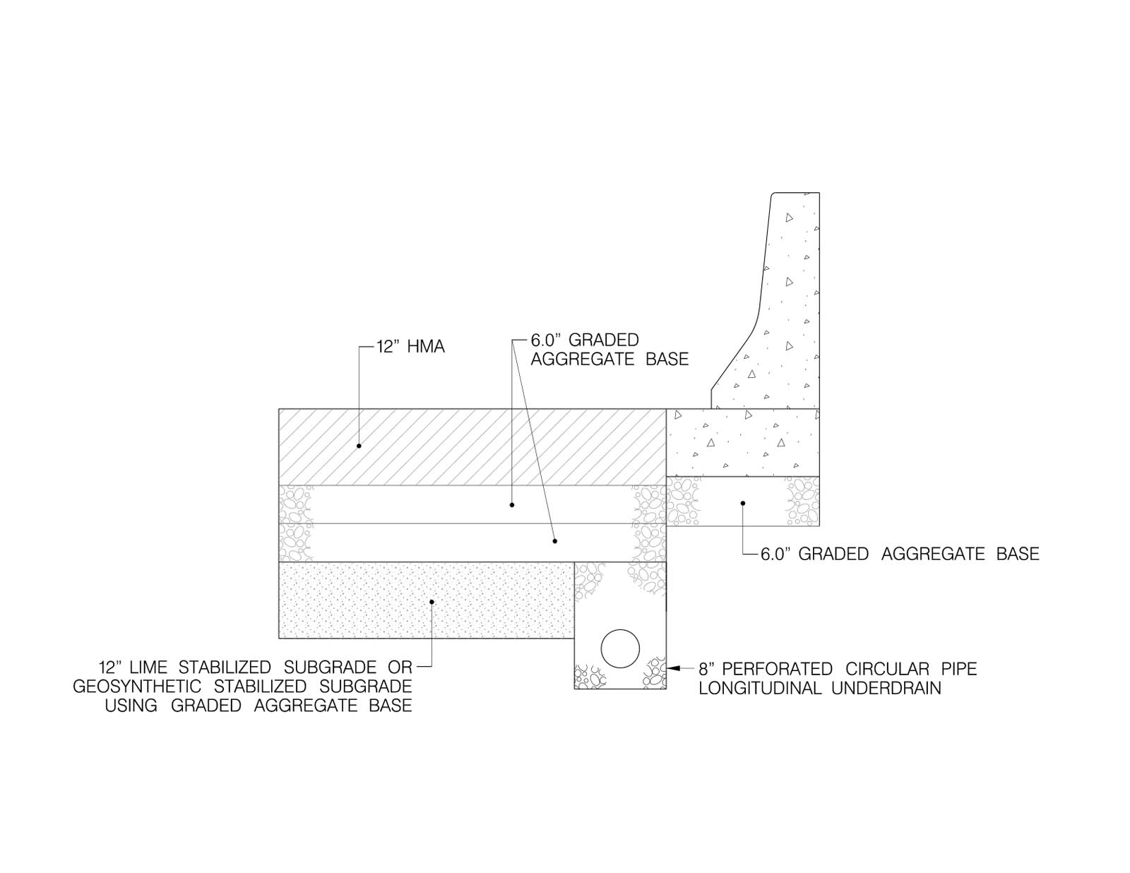
To address the potential detrimental effects of groundwater and drainage, it was decided to construct the first (lower) 12 inches (305 mm) of lift using an open-graded aggregate in order to provide a capillary break and prevent water that might enter the fill from either above or below from becoming trapped and potentially causing frost heave or weakening of the MSL. The second (upper) lift was constructed using a dense-graded aggregate base to provide a smoother and more stable surface that was suitable for construction. A nonwoven geotextile was placed above the first lift and below the second layer of multiaxial geogrid in order to maintain separation of the aggregate layers above from any fine-grained soil that might migrate into the capillary break layer. To direct groundwater from entering the drainage system, the MDTA standard pavement drain was modified to accommodate the new pavement section and lateral finger drains were added under the pavement. In areas where a third lift was used, the multiaxial geogrid was placed above the second lift, and the layer was completed with dense-graded aggregate base. Figures 2a and 2b show cross sections of the design.

The geotextiles specified were 6 ounces per square yard (203 g/m2) nonwoven (Class SD) and 8 ounces per square yard (271 g/m2) nonwoven (Class SE). The specified geogrids were integrally formed multiaxial geogrids with nominal aperture dimensions of either 1.6 inches (41 mm) or 2.24 inches (57 mm) that have been calibrated to the Giroud-Han method based on full-scale traffic testing.
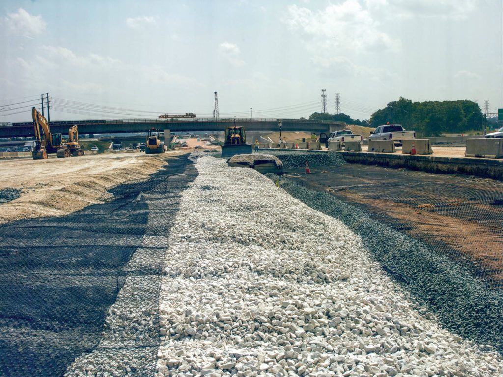
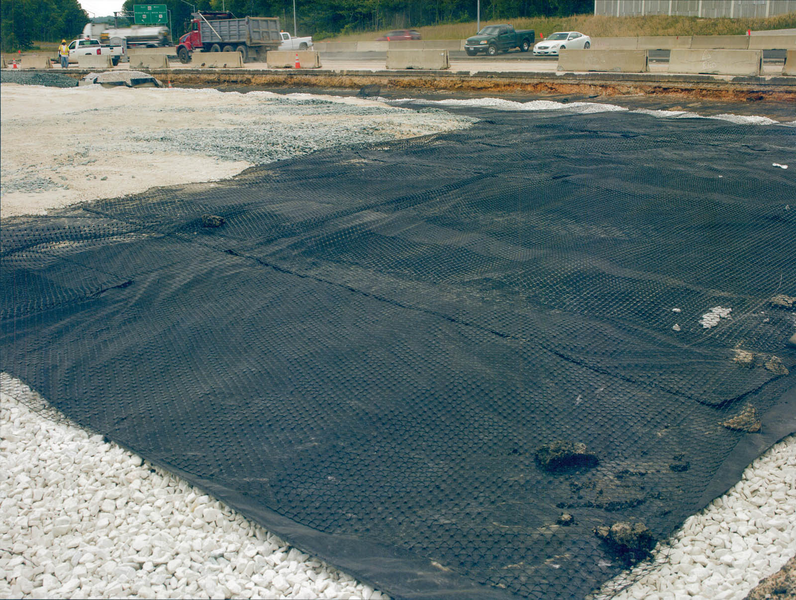
Once performance of the design was verified using test strips, the contractor worked with MDTA to put an appropriate change order in place, and the solution was implemented. Figures 1, 3 and 4 present photographs of the construction at the site.
Results
The original design included 12 inches (305 mm) of asphalt, 12 inches of GAB in soft areas and 12 inches of sand with a separation geotextile between the sand and the subgrade. The proposed treatment replaced the sand and separation fabric with two layers of geogrid and 24 inches (610 mm) of No. 2 stone. This required only an additional 12 inches of excavation. The MSL solution successfully addressed the issues related to unsuitable soils on the project and allowed construction to proceed on the toll lanes. The contractor was able to maintain the project schedule while addressing the site conditions, and the cost was significantly lower than would have been the case with the conventional solution of excavation, disposal and replacement.
Acknowledgments
The authors gratefully acknowledge the cooperation of MDTA, Tutor Perini Corp. and RK&K in developing and implementing the solution for this project, and look forward to continued success on future phases of the job.
References
Applied Research Associates Inc. and Ryan R. Berg and Associates. (2013). “Independent review and validation of Tensar’s modified 1993 AASHTO pavement design procedure and verification of SpectraPave4-Pro™ software.”
Giroud, J. P. (2009). “An assessment of the use of geogrids in unpaved roads and unpaved areas.” Presentation at the Jubilee Symposium on Polymer Geogrid Reinforcement–Identifying the Direction of Future Research, https://www.tensar.co.uk/jubilee-symposium/index.html, London, England.
Giroud, J. P. (2009). Calibration of the Giroud & Han method. Personal communication with Joe Cavanaugh, Tensar International Corp.
Giroud, J. P., and Han, J. (2004a). “Design method for geosynthetic-reinforced unpaved roads: Part I–Development of design method.” Jour. of Geotechnical and Geoenvironmental Engineering, 130(8), 775–786.
Giroud, J. P., and Han, J. (2004b). “Design method for geosynthetic-reinforced unpaved roads: Part II–Calibration and applications.” Jour. of Geotechnical and Geoenvironmental Engineering, 130(8), 787–797.
Giroud, J. P., and Han, J. (2011). “The Giroud-Han design method for geosynthetic-reinforced unpaved roads.” Geosynthetics, 30(2), 44–51.
Giroud, J. P., and Noiray, L. (1981). “Geotextile-reinforced unpaved road design,” Jour. of Geotechnical Engineering, 107(9), 1233–1253.
Bryan C. Gee, P.E., is director of education and training at Tensar International Corporation.
Eric Klein, P.E., D.GE, F.ASCE, is senior manager, geotechnical at RK&K/URS.
William T. Maier is northeast regioPROJECT HIGHLIGHTS I-95 lane widening OWNER Maryland Transportation Authority (MDTA) LOCATION Baltimore, Md. GENERAL CONTRACTOR Tutor Perini Corp. DESIGN ENGINEER RK&K/URS GEOSYNTHETIC PRODUCT Geogrid GEOSYNTHETIC MANUFACTURER Tensarnal manager at Tensar Roadway Systems.
All photographs and illustrations courtesy of the authors.