 TEXTILES.ORG

By Paul C. O’Malley, José L. Urrutia and Don DiGuilio
The two projects (confidential client) are industrial sites consisting of coal ash and by-product sludge located in the southeastern United States. The projects included 70 and 67 acres (28 and 27 ha) in closure areas, and the waste source consisted of industrial sludge with a California Bearing Ratio (CBR) of less than 1% in the top 10 feet (3 m) of waste elevation. The objective was to transition the sites into final closure while satisfying all environmental regulations and technical requirements in a cost-effective manner.
The closure of the sites was regulated through state and federal air-quality rules. Specifically, all gas coming from the sites needed to be collected and flared off. In addition, all leachate needed to be managed effectively to prevent groundwater contamination. The goal of the projects was to fully dewater with a stable and final impermeable cover that provided a long design life and minimal maintenance requirements. Figure 1 shows the completed 70-acre (28-ha) installation.

Additionally, the community sentiment toward these projects was strained due to historical and current odor problems. Improving community relations was a high priority for the solution selected and implemented.
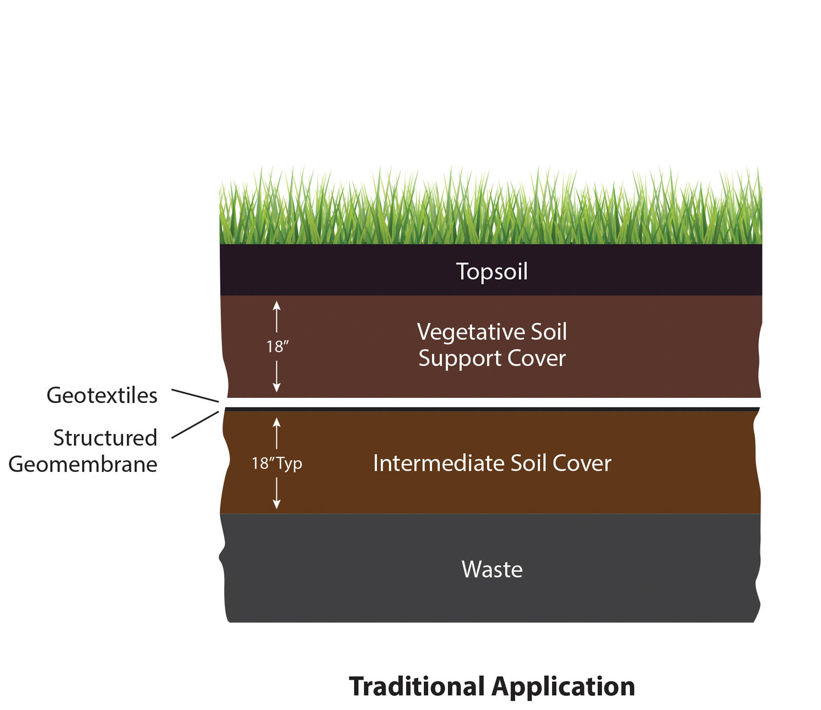
The traditional approach for remediating sites such as these would typically entail:
- Dewatering
- Adding fill as necessary to achieve desired grade
- Grading
- Installing an impermeable layer such as clay or a flexible membrane liner (FML)
- Adding a protective soil layer on top of the impermeable layer/liner
- Adding a vegetative cover layer on top of the soil layer to control erosion
An example of a cross section of a traditional final cover system is shown in Figure 2.
This traditional approach presented various challenges for the site conditions for these closures, resulting in investigating alternative methods that could reduce or eliminate some of the challenges. The most compelling challenge was the abundance of water in the waste pile. To dewater the sites to the point where consolidation could be achieved, and subsequent fill and grade activities could commence, would likely take one to two years. This process would also risk being protracted through exposure of the waste sites to continued precipitation. The projects are in a region that receives almost 50 inches (127 cm) of average annual precipitation.
During this time, the ongoing conflict with the local community over the odor emissions continued. In addition, the process of adding the necessary soil fill to achieve desired grade could require thousands of truck trips, equipment activity and associated construction disturbance for a few years. These activities would likely further strain relations with the local community.
In an effort to qualify solutions, the project team identified and prioritized the following objectives for the closures:
- Eliminate odor as quickly as possible
- Decrease overall construction schedule
- Minimize life-cycle cost (construction and maintenance)
With the primary objectives identified and prioritized, the project team chose an alternative solution that satisfied all criteria: a tufted geosynthetic final cover system (TG-FCS).
Overview of the TG-FCS
The TG-FCS is comprised of three primary components: a structured geomembrane, an engineered synthetic turf (tufted geosynthetic) and a specified infill for the tufted geosynthetic. A graphic representation of the system is shown in Figure 3.

The TG-FCS is comprised of individual components that perform the following functions:
- Structured geomembrane: This can be made from either linear low-density polyethylene (LLDPE) or high-density polyethylene (HDPE), allowing for local regulatory requirements. It provides an impermeable layer that prevents water infiltration into the waste area, thereby offering environmental containment.
2. Engineered synthetic turf: This is turf comprised of two layers of high UV-resistant geotextile, and provides a substrate into which the polyethylene (PE) turf fibers are tufted. The turf layer serves multiple functions:
a. Protection layer: This layer shields the structured geomembrane from UV radiation exposure.
b. Wind uplift protection: The turf roughness combined with the porous woven geotextile backing prevents wind from lifting either the turf or the geomembrane. This has been validated through independent wind-tunnel testing.
c. Infill containment: The PE turf fibers help to hold the specified infill in place, similar to how beach grass holds sand in place on sand dunes.
d. Aesthetics: The PE turf fibers, once infilled, provide a positive aesthetic benefit. The installed and infilled turf appears to be healthy, natural turf.
3. Specified infill: The selection of infill is determined by the application stresses anticipated for the designated area of the cover system. Regardless of the specific component type, the infill provides a cushion layer for the system, protecting the turf backing and geomembrane layer underneath from impact stresses and UV radiation exposure. The infill allows the installed system to be trafficked by rubber-tired and rubber-tracked equipment as well as wildlife. Additionally, it serves as a redundant ballast layer for the system. The following types of infill are currently available options:
a. ASTM C33 sand: Often referred to as “concrete sand” or “washed sand,” ASTM C33 sand is typically used on flat surfaces and slopes with relatively mild hydraulic sheet flow. The C33 specification provides an optimum particle size distribution so as to promote maximum interlocking of the particles, which when combined with the PE tufted fibers, yields less than 2% total cumulative particle movement.
b. Cementitious infill mix: Based upon a thin-set Portland cement technology, the cementitious infill is used in areas of high hydraulic velocity and shear stress typically associated with concentrated hydraulic flow, such as those found in downchutes or high-flow channels.
c. Emulsion binder: A polymeric binding agent is used in conjunction with the ASTM C33 sand to provide a hardened but highly permeable layer in which the sand ingredients are chemically locked into place. This binder will last a minimum of five years from initial application and can be recharged through the re-application of emulsion at a concentration rate of 10%–20% of the original rate to obtain at least five additional years of protection. The emulsion binder provides infill protection for transition zones between hydraulic and nonhydraulic areas, or for clients who wish to eliminate any possibility of sand infill movement, no matter how slight.
Project solution selection
The project team assessed the TG-FCS against the identified priorities of odor elimination, construction schedule and lifetime cycle costs.
Odor elimination
The TG-FCS provided specific benefits with respect to the odor elimination objective. The geomembrane could be deployed rapidly, containing the odor and preventing it from going off-site. With the odor contained, relations with the local community improved dramatically. This benefit to the client and project team cannot be overstated.
The TG-FCS eliminates the typical soil burden associated with traditional cover systems, as well as the corresponding heavy equipment needed to move, place and grade this soil. This system can be installed using only light ground-pressure vehicles. This allowed for far more rapid deployment of the geomembrane layer than would have otherwise been possible. Additionally, this eliminated the need for dewatering the sites prior to installing the system. Furthermore, the installation of the geomembrane layer prevented further recharge of precipitation into the waste area, reducing the amount of water that would ultimately be removed in comparison with the traditional approach.
Construction schedule
By choosing the TG-FCS versus the traditional method, the project team estimated the reduction in project schedules to be between 50% and 75%. The most significant contribution to the reduction of the schedules was the ability to install the impermeable layer without dewatering.
Once the structured geomembrane was in place, the installation contractor was able to install the engineered synthetic turf layer, followed by the specified infill component. All these activities were completed without having the sites dewatered first.
Additionally, by removing the soil burden and associated equipment, the construction schedules were not as affected by adverse weather conditions with the TG-FCS as they would have been with the traditional method. With the TG-FCS method, there is minimal wait for the work platform to dry out because the equipment is all low pressure. Also, once the geomembrane layer is down, there is no additional soil work, unlike with the traditional method. Finally, the weather challenges of managing a borrow pit are also eliminated.
Essentially, the project team discovered that with the TG-FCS option, if it started raining, work would need to stop; but once it stopped raining, work could commence again without waiting for the site and respective borrow pits to dry out, as is typically the case.
Life-cycle cost
In assessing the life-cycle cost of the TG-FCS versus the more traditional approach, the project team broke the comparison down into construction and maintenance categories.
With reasonably conservative assumptions around both methods, it was determined the TG-FCS method would be highly competitive with the traditional method, without factoring in the community dynamics or weather-related limitations that pertained only to the traditional solution.
Maintenance costs were simpler to evaluate. Once the TG-FCS was completed, the maintenance burden would be almost nonexistent. The system eliminated maintenance costs associated with traditional vegetative covers, including vegetative establishment, erosion repairs and vegetative maintenance (i.e., mowing).
The project team estimated an 80%–90% cost reduction of post-closure maintenance activities offered by the TG-FCS in comparison with the traditional method.
Project construction
Construction of phase I took nine months. Phase II also took nine months. The time it took to install the TG-FCS was less than the time estimated to dewater the sites for the traditional cover system.
The upper 10 feet (3 m) of the waste profile had a CBR of less than 1%, which complicated the installation process even for the TG-FCS. First, to get maximum capture of gas coming from the waste, a geocomposite drainage layer was installed with 100% coverage. The geocomposite drainage layer was tied into an active gas collection system for proper gas disposal.
The installation contractor utilized a slip sheet of sacrificial geomembrane for the field technicians to stand and operate on in deploying and seaming the geocomposite layer. This simplified the installation while providing an increase in worker safety and quality of the work. Installing the geocomposite was the most challenging part of the installation. Once the geocomposite was in place, it provided a more stable platform for the technicians to deploy and install the geomembrane layer. Standard geomembrane installation practices were utilized for this step of the process, including overlap and seaming, and construction quality assurance (CQA) procedures. Since odor elimination was the first priority, the team installed 100% of the geomembrane before proceeding with the engineered synthetic turf layer. Once the geomembrane was in place, the gas was captured, and the corresponding odor was eliminated. The installation process for the turf involved unrolling the turf and deploying the panels into place, securing adjacent panels together using a prayer seam.
The final component of the TG-FCS was the specified infill. Low ground pressure vehicles were utilized in deploying and placing the infill.
The profile of the site is fairly flat. This is due in part to the high water content and low strength characteristics of the waste. Precipitation drainage is managed through a network of bench drains that empty into a perimeter channel. Runoff from the TG-FCS has low turbidity due to the lack of soil in the drainage cross section as well as the filtering capabilities of the C33 sand infill. A common scale for measuring turbidity of water is the nephelometric turbidity unit (NTU) scale. Typical NTU ratings for runoff from the TG-FCS system are 11 NTUs. As a reference point, drinking water standards are usually 1–5 NTUs.
Post-installation activities
The decision to install the TG-FCS prior to dewatering accelerated the project schedules and helped to mitigate the odor problem very quickly. However, the water still needed to be removed from the waste. Fortunately, the TG-FCS allows for dewatering activities after installation. With the TG-FCS in place, precipitation is prevented from contributing to the water content in the waste, and existing water can be removed through a network of drainage pipes and pumped from the perimeter of the installation.
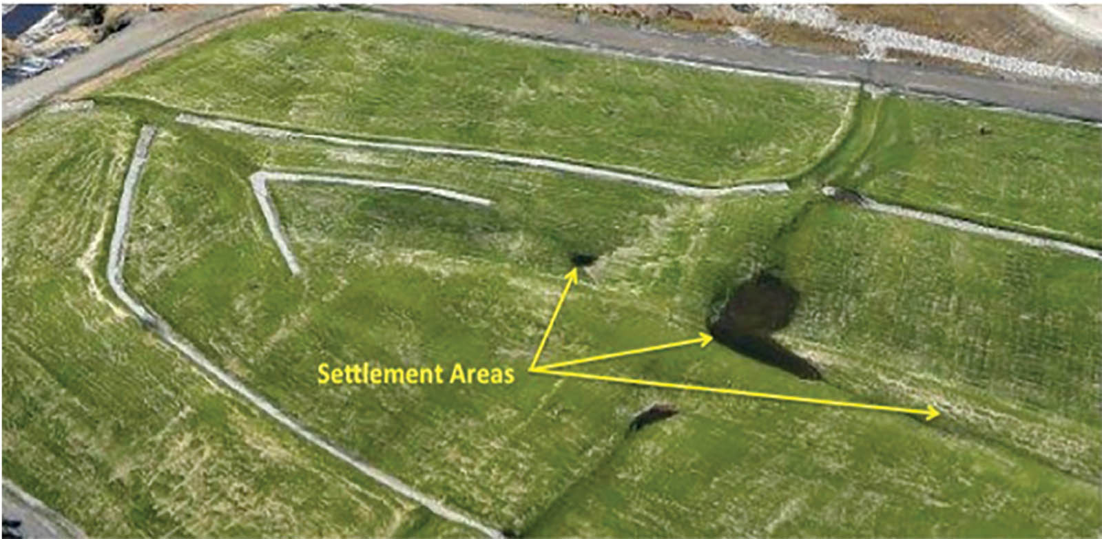
As the dewatering process is continued, settlement of the final cover surface can be observed. Due to the very high water content, the settlement expected and ultimately realized exceeded the category of differential settlement. The TG-FCS can accommodate aggressive settlement due to the high elongation values of its geomembrane component (i.e., 300% for LLDPE).
Once dewatering is finalized, the client can simply fill in any areas of aggressive settlement with lightweight fill and then install a mini-cap over the filled area, tying the geomembrane into the existing liner using an extrusion weld and then covering it with the engineered synthetic turf, which can also be fusion-welded to the existing turf via a hot-air gun. Once the geomembrane and turf are in place, the patch can be infilled and will blend in effectively with the surrounding area. An aerial view of the installation approximately two years after completion of the cover system, including the settlement area, can be seen in Figure 4.
Adoption by additional owners
The results of the TG-FCS and subsequent performance for the closures exceeded the client’s expectations, resulting in the selection of this method for additional closures in the U.S. by owners facing similar challenges at manufacturing facilities having waste with similar physical characteristics and at coal power generation utilities’ pond closures.
Conclusion
The ongoing development of innovative technology, such as the TG-FCS, provides the opportunity to approach traditional applications in new ways. In this example, the elimination of the soil burden associated with a traditional final cover system provided the following direct benefits: acceleration of project schedule; elimination of tens of thousands of hours of truck and equipment activity and resulting carbon emissions; near-zero maintenance burden of the final installation; and elimination of water quality threats due to the inherent low turbidity of the system’s runoff water. However, it was the implementation of a design and construction approach that was as innovative as the tufted geosynthetic that provided the most compelling benefits to the projects’ stakeholders. By focusing on odor elimination and choosing to close before dewatering, this project team differentiated itself in a meaningful and compelling way.
Paul C. O’Malley formerly served as vice president of sales with Watershed Geosynthetics LLC.
José L. Urrutia, P.E., is vice president of engineering with Watershed Geosynthetics LLC.
Don DiGiuilio is eastern region marketing manager with AGRU America Inc.
All photographs and illustrations courtesy of the authors.