Introduction
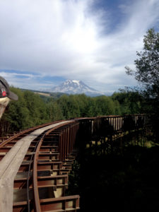
In 2015, a private hydroelectric company in Washington state was looking to install a geosynthetic liner as part of a 16-km (10-mi) elevated wood and metal structure for conveying water—a flume. The project was located near Mount Rainier (Photo 1) about 50 miles southeast of Seattle in southwestern Washington’s Pierce County.
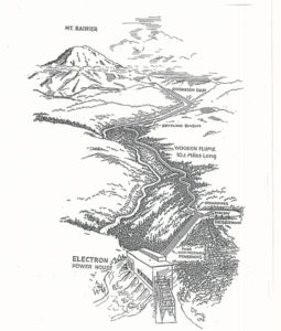
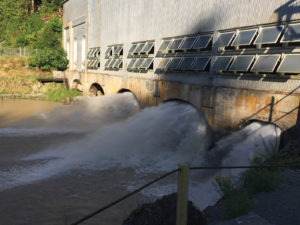
The owner operates a private hydroelectric facility that was originally built in the early 1900s. The facility includes an intake structure, the wood-constructed flume, a sediment basin and storage pond, steel penstocks, and a powerhouse (Photos 2 and 3). The process requires conveying water that is diverted from the Puyallup River at an intake diversion into the meandering wooden flume structure downstream to the hydroelectric generating plant.
The flume
The flume is supported by approximately 6,200 bents, of which about 1,200 are made from wood. The Puyallup River is fed from glacial melting, which can contain high sediment loads and flow capacity during the summer months.
In many areas of the flume, the wooden floors and walls were badly decayed and leaking significant quantities of water. The inside dimension of the wood flume structure is approximately 2.4m (8ft) wide × 2.6m (8.5ft) high. The hydroelectric plant has an operating capacity of 26 megawatts (MW). However, as a result of the structural decay of the flume, there was significant water leakage resulting in the plant operating only at 8MW.
Project scope
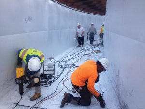
The project scope included two crews concurrently installing the geomembrane liner (Photo 4) in opposite upstream and downstream directions of the flume. The materials included 140,000m² (1,506,000ft²) of 2.5mm (100-mil) and 2.0mm (80-mil) white high-density polyethylene (HDPE) geomembrane and steel anchor bar (Photo 5). Custom material widths were produced from the installer’s plant in Vancouver, B.C.
The project also required the installation of 165,000m² (1,775,400ft²) of high-strength geotextile under the geomembrane to help structurally reinforce the deteriorating wood flume. There was concern that some of the walls of the weak wood structure would fail as the wood dried out further and became more brittle.
A high-strength geotextile with an ultimate wide-width tensile strength of 105 kN/m (600 lb/in.) in both machine direction (MD) and cross-machine direction (CMD) was chosen for the project during the design process.
Project challenges
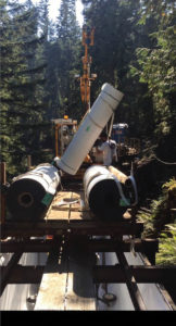
The flume project faced many challenges as a result of difficult site access and tight space constraints. Because there was no roadway or vehicle access other than the three staging areas, all project-related materials had to be transported using a special railcar and track located above the flume (Photo 6).
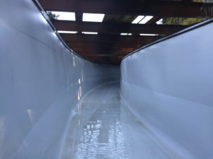
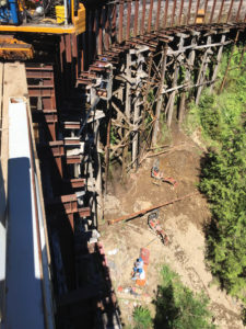
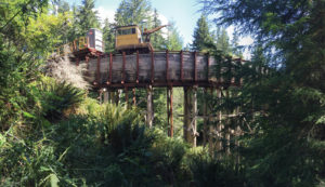
The workers had to deploy, weld, and mechanically attach the geomembrane in the confined space inside the flume. The tight inside dimensions of the structure required specially designed deployment carts to hold the geosynthetic rolls during installation (Photo 7). The flume was also elevated in some areas as much as 12.3m (40ft) above ground requiring special safety precautions (Photo 8).
Conclusion
The flume project was completed in the fall of 2015 on time and on budget. The re-lining of the structure was estimated to extend the life of the flume by 10 years. It also tripled the operating capacity of the hydroelectric plant.
This was truly a unique project showing how conventional geosynthetic materials, combined with some installation ingenuity, can be used in structural applications to protect and safely convey water.
Brian Fraser is vice president at Layfield Environmental Containment.
 TEXTILES.ORG


