 TEXTILES.ORG

By George R. Koerner
As you can see by Figure 1, we are experiencing a new age of geosynthetics. Over the past 15 years, we have seen a propensity of polymeric materials left exposed to rather than covered from the environment. This is in large part due to the strides geosynthetic manufacturers and polymer formulators have made in creating long-term durable materials.
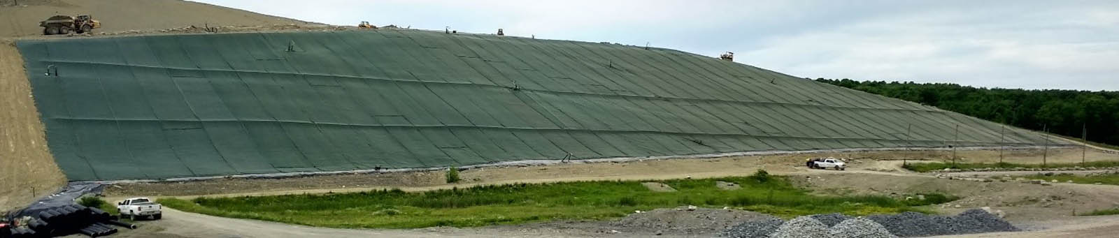
Open literature is full of cautionary tales of wind uplift on geomembranes. When a geosynthetic is caught in high winds, there is a possibility that it can be damaged (wrinkled, torn, stretched, etc.), depending on the wind velocity, the altitude above sea level and the facility location; however, the benefits of leaving a geosynthetic exposed, specifically not needing cover soil, can sometimes outweigh the risk.
One thing that has not been standardized is a test method to characterize how a geosynthetic performs in the wind. Material wind damage assessments of specific materials are now available through two configurations (flag and awning) wind tunnel tests. These tests will allow us to make practical recommendations on how to create more wind-resistant materials and help us minimize the magnitude of damage caused by the wind on exposed geosynthetics.
The “wind whip” behavior of geosynthetics is a phenomenon defined by measurable negative property changes in a coupon after exposure to sustained wind speeds over time. We can now simulate this environmental phenomenon in a controlled laboratory setting using a commercially available wind tunnel. The properties for evaluation of exposed specimens can be compared to the unexposed “as-received” material properties, yielding a percent retained value. The target properties include tensile performance, normalized thickness and mass per unit area. In addition, qualitative observations (wrinkles, fraying, cracking, flaking, exposed scrim, etc.) of the material can be contrasted before and after exposure in the wind tunnel with a controlled speed and duration of laminar flow.
Wind whip prevention is an important concern for environmentally exposed geosynthetics. In addition to developing design strategies to limit the degradation of geosynthetics in high winds and understanding the different factors affecting geosynthetic performance (geometry, formulation and structure), quantifying and studying the wind-whip phenomenon is important to better understand the durability of geosynthetic materials. This standard will serve as a vital indicator of fatigue performance for long-term wind exposure, thus aiding an engineer in the geosynthetic selection process.
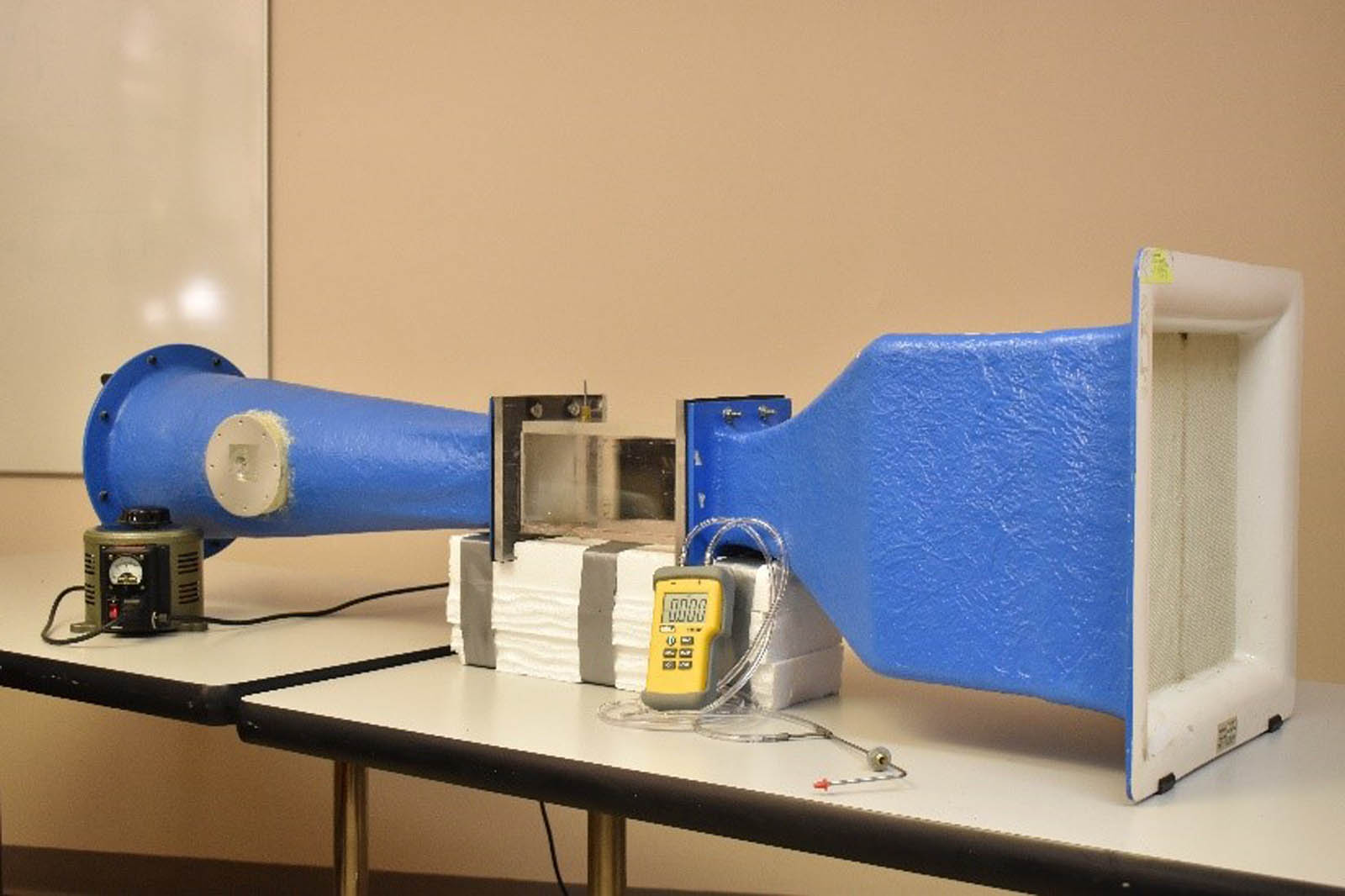
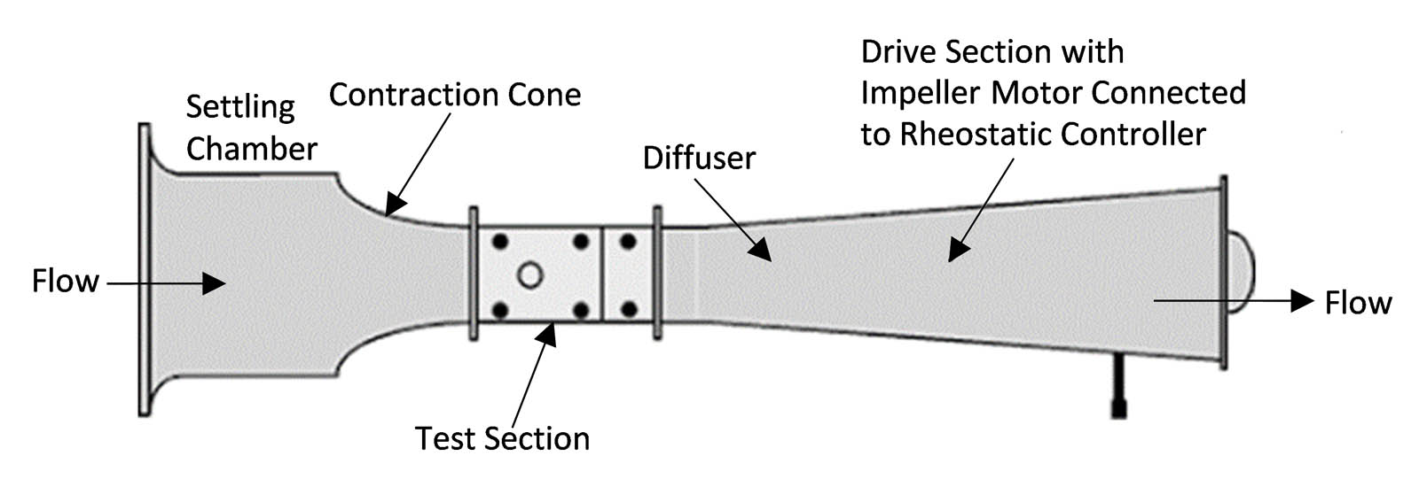
The requirements of the wind tunnel used in this experiment are as follows and can be seen in Figures 2 and 3: robust construction, ability to produce a laminar (nonturbulent) flow profile at a specified velocity, and ability to sufficiently dampen vibrations from both the motor and fluttering test specimen. For this method, a subsonic wind tunnel will be utilized, which is able to produce wind speeds between 9 and 150 mph (15 and 240 km/h), which is far below the speed of sound (761.2 mph [1,225 km/h]). The rationale for this selection is that Category 4 hurricane and F2 tornado wind speeds are approximately 100 mph (160 km/h). There is no reason to surpass these extreme velocities when testing geosynthetics.
Before performing any tests with the benchtop wind tunnel, it is extremely important to verify the performance of the entire tunnel system, as well as the precision and accuracy of the digital manometer; therefore, a three-part process is to be used: 1) verification of a calibration equation, which converts motor voltage to wind tunnel air velocity; 2) velocity-drop and pressure-drop verification tests using a standardized flow-restrictive orifice plate; and 3) testing of a known internal reference material (IRM). All of these are described in detail in GRI-GS24 “Detecting the Wind Whip Resistance of Geosynthetics.”
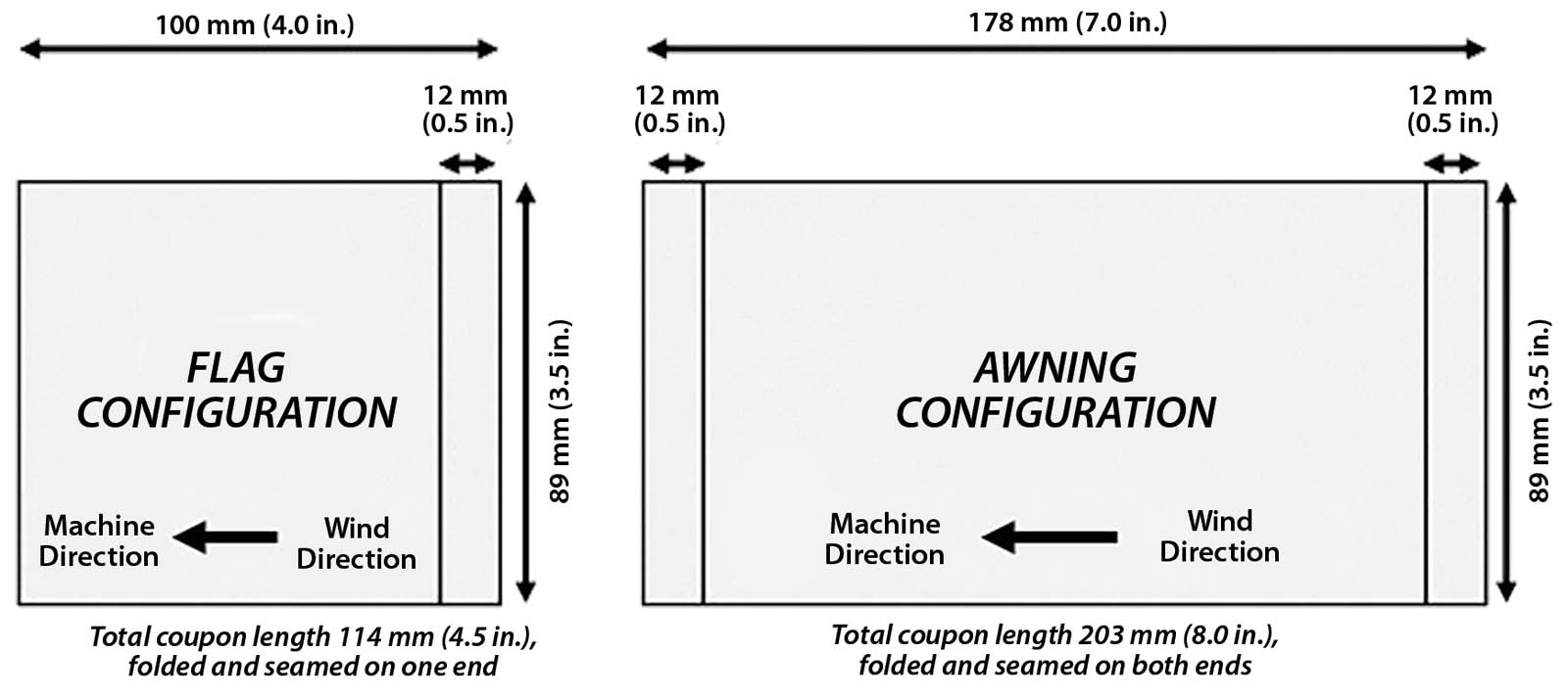
The wind tunnel can be set up in either a flag (Figures 4a and 5a) or an awning (Figures 4b and 5b) configuration.
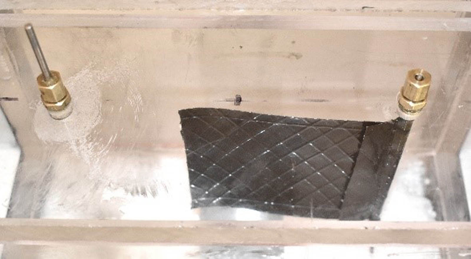
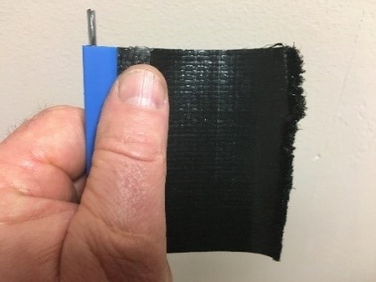
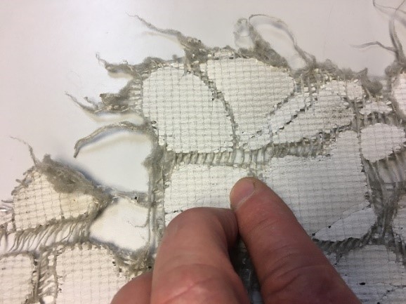
The wind tunnel is programmed to achieve 100 mph (160 km/h) for 1, 2, 4, 8, 16, 24 and 48 hours unless otherwise specified. The operational fluctuation should not be greater than ±5 mph (±8 km/h) over the duration of the exposure. The coupon is removed from the apparatus after the appropriate number of hours of wind exposure time for material evaluation. It is prudent to make observations and photograph the coupon before and after the periodic exposure times. Examples of wind-related geosynthetic damage are shown in Figures 6a, 6b and 6c.
Test methods to be utilized for a quantitative evaluation process for both unexposed and exposed coupons include ASTM D5035 Strip Tensile, ASTM D5199 Thickness and ASTM D5261 Mass Per Unit Area. The percent retained values for these properties can be calculated for each exposure time and contrasted over time.
In summary, there now exists a new tool to evaluate index geosynthetics’ wind resistance. It allows exploration of the new paradigm of geosynthetics in exposed applications on a very basic level. It does not purport to simulate wind whip experienced by full-scale geosynthetic panels. It is likely that there may be some significant differences in the dynamics of full-scale experiments, such as larger inertial forces and potentially much higher drag forces disproportional in scale to the index test being conducted; however, this method is a first step in conformance testing to a specification or establishment of saturated process control (SPC) database for materials used in such applications.