 TEXTILES.ORG

George R. Koerner
This article describes a large-scale test method intended to determine the leakage through imperfections in a geomembrane (GM) under a given head. It can be used as a performance test to simulate field conditions where the GM is physically breached. The test method places a GM test specimen of 2 feet (0.6 m) in diameter on a subgrade within a high-pressure test vessel. The GM can be underlain by a geosynthetic clay liner (GCL), thus comprising a composite liner system. Upon adequate sealing of the GM around the perimeter and closing of the upper portion of the vessel, hydrostatic plus normal pressure can be applied to the specimen by a control panel system attached to a pressure vessel cell. Note that the normal pressure is applied by an additional rubber bladder over the top of the assembled cross section. The leakage through any imperfection in the GM can be monitored at differential pressures by a flow measurement system attached to both the influent and effluent lines, above and below the GM respectively.
This test method is used to evaluate the rate at which liquids leak through holes, slits or cracks in a GM by itself or as a component of a composite liner system. In this regard, the GM is underlain by a GCL, thus it becomes a GM/GCL composite liner. The relatively large pressure vessel used for this experiment can accommodate a number of variables: e.g., flaw size and shape, GM type and thickness, the influence of a geotextile (GT) in the cross section, the permeability of the soil subgrade and overburden soils, the liquid head, and the liquid characteristics.
Imperfections in GMs can be characterized into those resulting from either physical factors (Kays 1977) or chemical or biological factors (Haxo 1982). Physical failure mechanisms include punctures that may result from equipment pressure or soil (subgrade or overburden). These mechanisms may also include tears, creep, freeze-thaw cracking, wet-dry cracking, differential settling, thermal stress, differential hydrostatic pressure, abrasion and seam failures. Chemical failures are caused by deterioration that results from factors such as ultraviolet light, oxidation, hydrolysis, extraction or solvent attack. Causes of biological degradation include factors such as microbial attack, burrowing animal attack or damage resulting from animals trying to escape from inside a containment facility.
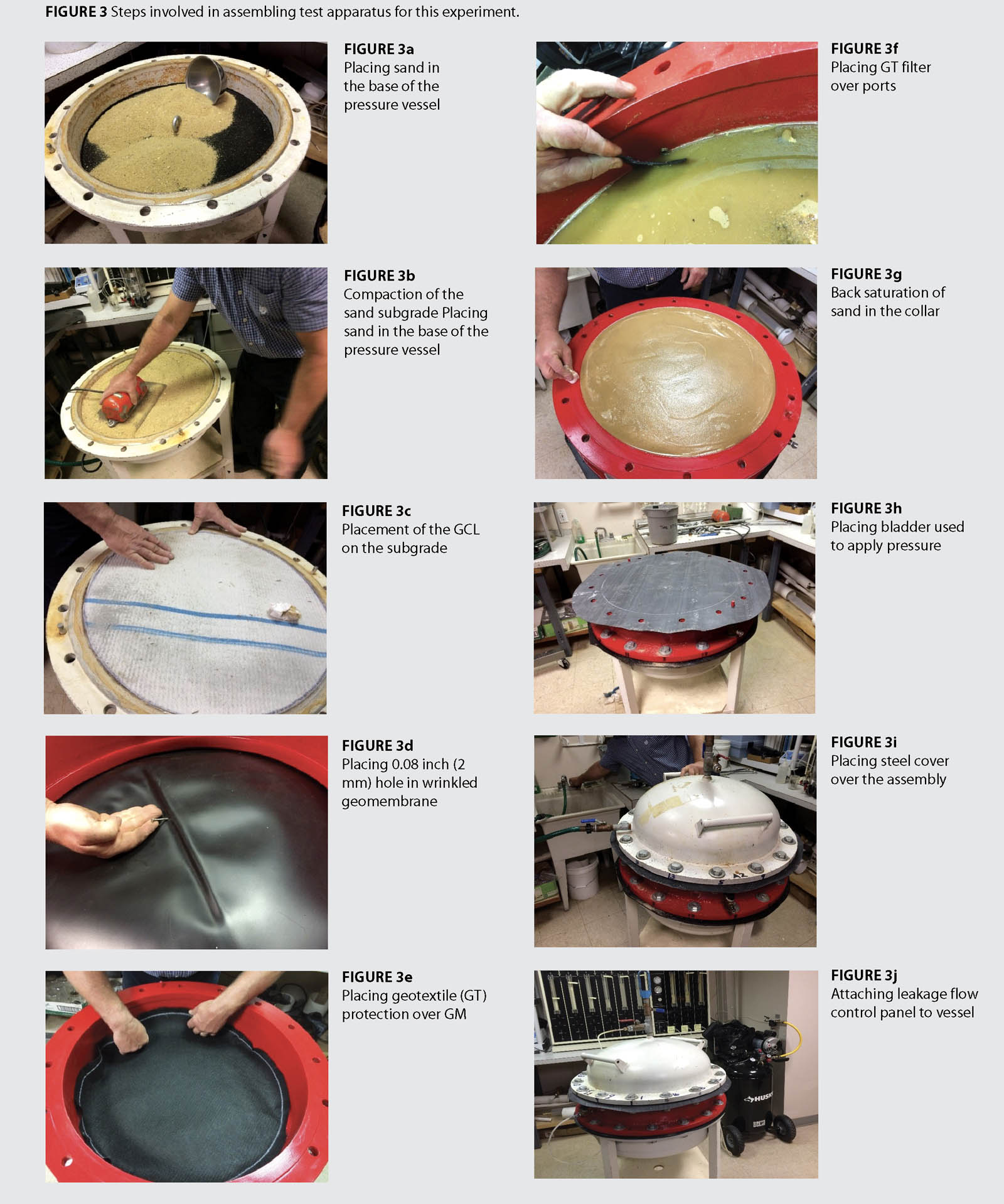
At the present time, there exists a considerable amount of theoretical knowledge on leakage rates through such flaws in liner systems. Therefore, it is important that leakage rates be quantified and the principles governing leakage rates be understood so that better predictions of in situ performance can be made. This investigation will illustrate the leakage through a composite GM/GCL liner system. The GCL is in intimate contact with the underside of the GM except for the section of GM fold, which can be seen in Figure 3d of the setup.
To experience leakage through a liner system at a greater rate than diffusion, one needs a physical perforation in the GM, i.e., a “hole.” To compound this preventable defect, a wrinkle with a crack may exist where the GM is not in intimate contact with the GCL. Holes and wrinkles may be modeled as described by Rowe (1998).
This article focuses on holes and wrinkles that are either circular or have dimensions such that they can be reasonably approximated as circular. In the case where there is a crack in a wrinkle, the flow will be controlled by the capacity for flow through the crack (Giroud and Bonaparte 1989), particularly in the zone where there is no intimate contact between GM and GCL (Rowe 1998). Results in this study were obtained for a round hole size of 0.08 inch (2 mm) and were compared with baseline estimates from Forcheimer (1930), Rowe (1998) and Giroud and Bonaparte (1989).
Test apparatus and equipment
The test apparatus used for this investigation is shown schematically in Figure 1. It consists of a pressure vessel rated up to 100 psi (690 kPa), which can accept a GM test specimen of approximately 2 feet (0.6 m) in diameter that is subsequently bolted between flanges. Suitable pressure pumps, valves, regulators and gauges are used for the purposes of control and operation.

There is a lower containment vessel that contains the subgrade soil. If a geotextile protection layer is to be used, it should be located directly on top of the soil or beneath a GCL in the case of a composite liner. In addition, there is an upper assembly consisting of a domed steel cover with pressure gauge, air bleed valve, water control valve and water intake. It should be clearly stated that the vessel has three main parts: from the bottom up, the base which contains the subgrade soil and composite liner system, the central flange filled with soil and water, and finally the upper domed lid with a rubber bladder between the central flange and lid for applying normal pressure.
Attached to the pressure vessel is a permeability control panel, shown in Figure 2, which controls and monitors the normal pressure on the system as well as the flow through the liner system. The system is capable of maintaining constant hydraulic pressures to within ±5% and includes means to measure the hydraulic pressures to within a prescribed tolerance. In addition, the head loss across the test specimen can be held constant to within ±5% and can be measured with the same accuracy or better. Pressures are measured using electronic pressure transducers connected to a digital readout, and flow is measured with the burette panel.
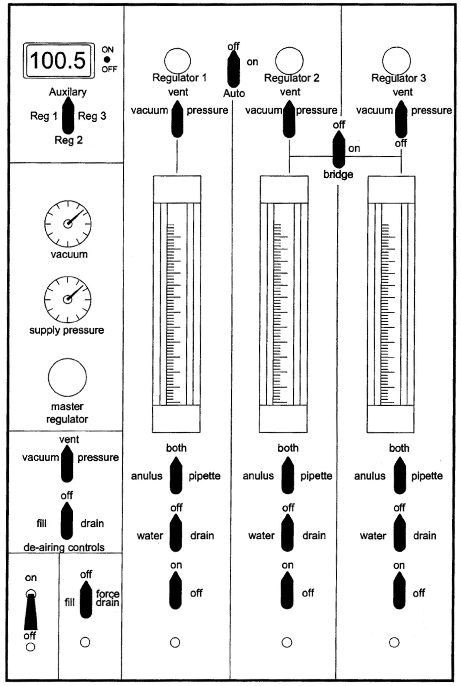
Water is the liquid used to both permeate and pressurize the test specimen. The flux through the system will be substantially influenced by the permeating fluid. Deionized water is being used in standardized testing and also for these tests. However, any other liquid, e.g., leachate, may be used going forward.
Test procedure
The pressure vessel, materials and control panel are configured as shown in the series of photographs in Figures 3a–3j. Figure captions describe the various stages in the setup. It is important to mention that the soil under GM is back saturated by introducing water into the space under the GM until it is full, assuring that no air pockets exist in the flange or lid of the apparatus. The pressure on the system is gradually built up until the targeted value is reached. In this test, the targeted value was 7 kPa for saturation. Subsequent to this, the normal pressure is built up incrementally throughout the experiment.
It should also be noted that the following termination criteria was used for each reading of the test: three flow values over 8 hours where inflow=outflow; no up or down trends in results; and three values of 0.2% on average. With this in mind, 30 average results were collected at five normal pressures and six hydraulic heads.
The flux (q) was calculated, as follows:
q= Q/A t
where:
q = flux, (m3/m2-sec)
Q = quantity of flow, taken as the average of inflow and outflow, m3
A = cross-sectional area of apparatus, m2
t = interval of time, s, over which the flow occurs
One calculates the hydraulic conductivity of the system knowing the thickness of the composite liner system, which in this case is 0.35 inch (9 mm) (i.e., GM=0.04 inch [1 mm] and GCL=0.31 inch [8 mm]).
Results
Presented is a test that took four months to complete due to very long saturation-equilibrium times (1.5 months), in which we could only run one setup. The experiment we chose to run was with the 0.08-inch (2-mm) round hole in the GM with a 1-inch (25-mm) wrinkle that was underlain by a GCL. The two geosynthetics forming a composite liner system were a 0.04-inch (1-mm) thick linear low-density polyethylene (LLDPE) GM and an 0.31-inch (8-mm) thick GCL. The setup had a wrinkle in the GM, and the setup was saturated. The hole was located at the 180° bend of the wrinkle. The two variables during the test were hydraulic head and normal pressure. The hydraulic head was varied by creating a pressure differential across the composite liner system. The pressure head differential was modulated in the following steps: 0, 3, 14, 35, 70 and 98 kPa. This corresponds to 0, 0.3, 1.4, 3.5, 7.0 and 10 meters of hydraulic head across the liner system. The normal pressure of the apparatus was systematically varied. It was increased per the following schedule: 0, 7, 69, 138, 276 and 552 kPa. It should be clearly stated that it was incrementally increased through the entire normal pressure sequence at each hydraulic head to obtain the five laboratory curves of Figure 4. Therefore, no bentonite was lost beneath the defect in advance of collecting a data set over a normal pressure range for each gradient.
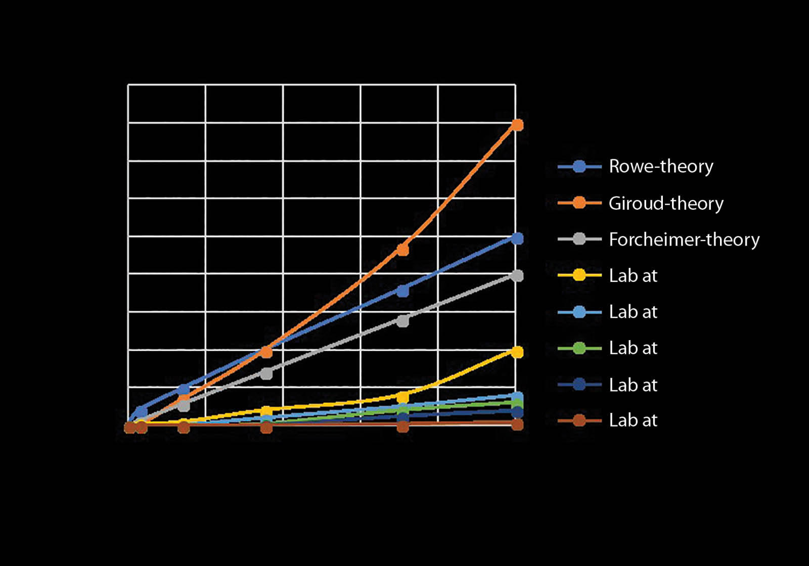
In Figure 4, the five laboratory-generated leakage curves behave well with the lower normal pressure, producing the highest leakage and progressively lower leakage at higher normal pressures. Additionally, three theoretical leakage models were used for 0.08-inch (2-mm) holes; they were Rowe (1998), Giroud and Bonaparte (1989) and Forcheimer (1930). All three have significantly higher flow rates than the laboratory curves; however, this could very well be due to the GCL being beneath the GM in the lab tests. Such a GM/GCL composite liner was not considered in these three theoretical papers, only the GM by itself.
Summary and conclusions
This article describes a large-scale laboratory device used to measure leakage through a GM or GM/GCL barrier system in an accurate simulation of the field. The targeted hydrostatic pressure applied to the test specimen should simulate the equivalent of the design pressure, which will be applied to the test specimen to determine if the design value can be sustained. A wide variety of subgrade conditions are capable of being assessed. For example, different soil conditions, different subgrade placement conditions, effect of sharp objects, effect of a geotextile protection layer, wrinkles, folds, waves, etc., are all possible options. Obviously, each of these field situations can have punctures, holes, tears or cracks in the GM. Used in this preliminary study is a GM/GCL composite liner with a 0.08-inch (2-mm) hole in the underside of a wrinkled LLDPE GM. The following was observed:
- Experimental leakage is lower with decreasing hydraulic head.
- Swelling bentonite from the GCL may be filling the hole, limiting leakage.
- Leakage is less with increasing normal pressure.
- Suspended solid particles from the overburden sand may be migrating into GM defects causing a reduction in leakage rates through any such defects.
All three theoretical solutions for calculating leakage through GMs overpredict the actual leakage rates obtained in our experiments, although none evaluated flow through a GM/GCL composite liner.
Thus, the leakage models provide an overestimate of the leakage rates through GM defects with no GCL underliner. The lab verification provides a lower bound estimate for the case where the liner is overlain by significant overburden and is part of a composite liner system.
Acknowledgments
The financial assistance of the member organizations of the Geosynthetic Institute and its related institutes for research, information, education, accreditation and certification is sincerely appreciated. Their identification and contact member information is available on the institute’s website, www
.geosynthetic-institute.org.
References
Forcheimer, P. (1930). Hydraulik, 3rd ed., BG Teubner Verlag, Leipzig, Germany.
Giroud, J. P., and Bonaparte, R. (1989). “Leakage through liners constructed with geomembranes—part I. GM liners.” Journal Geotextiles and Geomembranes, 8(1), 19–37.
GRI Test Method GMXX. Standard test method for determining leakage thru imperfections in liner systems using a large-scale simulation device (under review), Folsom, Pa.
Haxo, Jr., H. E. (1991). Compatibility of FMLs and MSW leachates, EPA/600/2-91/040, Risk Reduction Lab, Cincinnati, Ohio.
Kays, W. B. (1986). Construction of linings for reservoirs, tanks and pollution control facilities, 2nd ed., John Wiley and Sons, New York.
Rowe R. K. (1998). “Geosynthetics and the minimization of contaminant migration through barrier systems beneath solid waste.” Proc., 6th Int. Conf. on Geosynthetics, IFAI, Atlanta, Ga., 27–180.
Terzaghi, K., and Peck, R. B. (1987). Soil mechanics in engineering practice, 2nd ed., McGraw Hill, New York.