 TEXTILES.ORG

By Laura Carbone, Ole Syllwasschy and Lilma Schimmel
In the past, the Soviet-German stock company Wismut carried out an intensive uranium mining operation resulting in a large amount of polluted tailings containing daughter nuclides of uranium (Koß 1997) that were released into industrial sediment ponds (named IAA). The tailings “Pond 4” was built in 1957 and worked as a settling basin for residues of uranium ore treatment from January 1958 to December 1960. Due to its morphology, the pond acted also as a rainwater retention basin, and in 2006, the regional Authority of Water Management declared Pond 4 as a contaminated site to be remediated.
Generally, the management of tailings ponds consists of three main steps: solid-liquid separation, sludge dewatering and disposal (Zinck 2005).
For Pond 4, the remediation concept consisted of an impermeable capping, which mainly aimed at 1) isolating the residues and therefore reducing the exposure of uranium radiation, and 2) preventing new leakage formation by limiting the infiltration of water into the pond.
In Pond 4, despite the very soft subgrade, the construction of the cover system has been made possible thanks to the introduction of geosynthetics into the system combined with the use of vertical drains in some areas of the pond (Figure 1). In this article, the remediation of Pond 4 in Freital, Germany, through an impermeable capping is presented. Particular attention is given to the use of geosynthetics in the system. Thus, a detailed description of the use and design of the geosynthetics for the Pond 4 capping system is presented. The stability analysis, the selection of the materials and the installation phases are described.
Capping system of impoundments: Main generalities
Impermeable capping systems mainly aim at:
- isolating the residues and therefore reducing the exposure of the contaminated materials
- preventing new leakage formation by limiting the infiltration of water into the pond
An impermeable cover system for pond closure is composed of a sealing layer, a drainage layer and topsoil. The layers and their thicknesses may vary according to the regulations in force in every country and to the end use of the site after the remediation work.
For the technical design of a capping system, an intensive investigation of in situ soils is required. The following data are requested:
- geotechnical parameters of tailings/fill material
- stratification of the subsoil
- tailings pond size
- free water level
- live load of construction machinery
The main challenge involved with the capping/closure of lagoons and impoundments is the weak nature of the material being covered and the variability of the mechanical characteristics with location and depth. Soil strength parameters are used to perform stability analysis in order to evaluate the load that can be submitted to the subgrade or to calculate the strength of the geosynthetic for reinforcement to be used to increase the bearing capacity of the subgrade.
Geosynthetic reinforcement design
Currently, there is no generally accepted method available to design the geosynthetic reinforcement according to the membrane-like loading effects. Edil and Aydilek (2001) described a design procedure and Espinoza et al. (2012) presented a case history and a more sophisticated design method. These designs are based on bearing capacity analyses in combination with membrane contribution of the reinforcement. Additionally, Bishop’s method can be used for the stability analysis in order to assess the behavior of the soft tailings during the filling progress at the edge of the geosynthetic.
Sometimes analysis based on wedge or slice methods (e.g., Janbu) may be advantageous compared to circle methods (e.g., Bishop, Krey) because of the better considerations of the contribution of the geotextile reinforcement. Within the circle design methods, the reinforcement is considered as a moment that is strongly influenced by the choice of the midpoint as well as by the length of the lever arm. This can lead to inadequate consideration of the horizontal forces of the geotextile (Zinck et al. 2007).
Regarding the stability of the system, typical values of undrained shear strength of the tailings—ranging approximately between 0.07 and 0.73 psi (0.5 and 5.0 kPa) can be used and the factor of safety has to be checked for each stage of filling. The stratification of the cover layers and their soil parameters must be checked carefully in each stage of filling. Especially the first soil layers up to 2.0–3.3 feet (0.6–1.0 m) may be critical. At this stage the shear resistance of the weak sludge as well as the counterpressure activated by surcharge is negligible. Therefore, ground failure is likely to occur. To overcome this problem, the use of light machinery with very small live load and the installation of thin soil layers, up to a maximum of 12 inches (30 cm), should be used.
Another aspect that has been considered in the design when geotextiles are used in the system (both woven and nonwoven) is their long-term filtration behavior with respect to clogging effects. Filter stability analyses have been carried out and, in general, geocomposites or woven materials having apparent opening sizes O90 in the range from 0.08 to 0.2 mm showed good dewatering and settlement effects. Both effects increase stability during and after the construction period (Syllwasschy and Wilke 2014).
Settlement estimation
Settlement due to consolidation may be significant and it should be assessed and consistent with the allowable deformation of the sealing system.
Soil investigation should contain consolidation tests to specify settlement during and after the construction period. If there are no data available, a settlement assumption must be done based on experience in comparison with similar soils. It may be useful to install measuring points on the surface of the sludge to allow control of settlement during the filling process and verify against the estimated values, thereby adjusting the gradient if necessary.
Geosynthetic selection and installation methods
Typically, woven fabric, geogrids or composite materials like woven/geogrid or geogrid/nonwoven can be selected for the capping system. The main function of woven fabrics and geogrids is to transfer into the anchor trench tensile stresses resulting from soil and traffic load across a larger area. In addition, a nonwoven can also work as a separator and filter to keep sludge in place below the geotextile.
Depending on the chemical characteristics of the tailings, different raw materials should be selected. Normally polypropylene (PP), polyester (PET, PES) and polyvinyl alcohol (PVA) can be used in a normal pH range from 2 to 9.5. In areas with pH 10 to 13 where long-term stability must be considered in the design, only PP and PVA may be used.
The installation of the geosynthetics depends on the size of the pond and on the tailings characteristics. It can be done by unrolling and overlapping them or by sewing a large panel pulled by external edges into the pond.

Cover system: Pond 4
The cover consists of the succession of mineral soils and geosynthetics designed according to the storage and evaporation principle with a total thickness of about 6.6 feet (2 m).
The final cover contains the following layers (from the bottom to the top) (Figure 2):
- tailings
- nonwoven
- two layers of geogrids (installed perpendicularly to each other—T-shape)
- vertical drains
- mineral drainage and bearing layer
- mineral sealing layer ensuring hydraulic conductivity k ≤ 1∙10-9 m/s
- soil cover
Vertical drains have been included in the system to make possible the installation of the mineral layer on a very soft subgrade (i.e., saturated tailings); a nonwoven geotextile was used as a separation and filtration layer; and two crosswise geogrids were introduced into the system as a reinforcement element.

Depending on the position, the stored tailings differ in their physical behavior. According to the tailings characteristics, three main different areas can be identified (Figures 3a and 3b). While the tailings in the outer edge and middle region can be considered as partially dewatered and partially consolidated, the tailings located in the central area under the free water level is mainly very fine-grained material that can be considered in a saturated and unconsolidated state.
First, the removal of the surficial water was carried out. Afterward, the vertical drains were installed to enhance the consolidation process and expel pore water followed by the placement of the drainage mineral layer that will serve both as a working platform and as a surcharge load to enhance consolidation. The installation of this layer is possible thanks to the nonwoven layer acting as separation and the two layers of geogrids to enhance the load-bearing capacity and improve load distribution. The schematization of the remediation concept for Pond 4 is shown in Figure 4.

The expelled contaminated water was then collected and treated. On top of the drainage layer, a properly compacted mineral sealing layer was installed followed by the cover soil layer.
In the outer edge regions, outside the water profile, the subsoil in the bank zone can be considered as dried. In this area, favorable conditions with regard to load-bearing capacity can be assumed. Therefore, the trenches to anchor the geogrid were built on this area. First, the nonwoven fabric (E 250 K4) was rolled out as a filter and separation layer. Subsequently, the first geogrid layer (Base 40) was placed rotated 90° to the nonwoven direction. The overlap between the different geogrid panels was at least 20 inches (50 cm). The next step was the installation of the second geogrid layer (Base 40) for load distribution rotated 90° to the first geogrid position and parallel to the lowest nonwoven. This method enables forces from machineries to be transferred in the longitudinal and transversal directions in a trench area so that the overlap between the panels will not be overstressed.
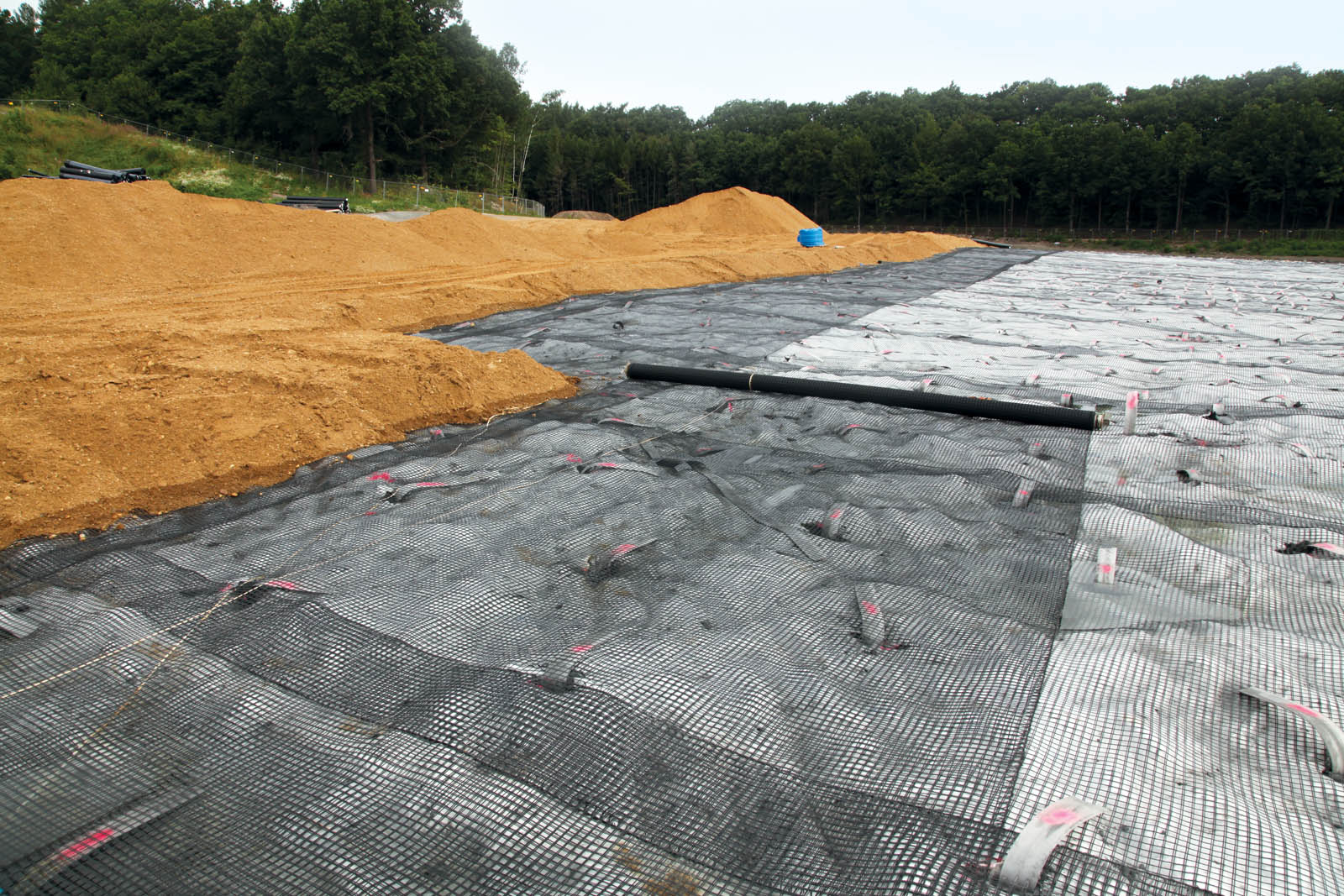
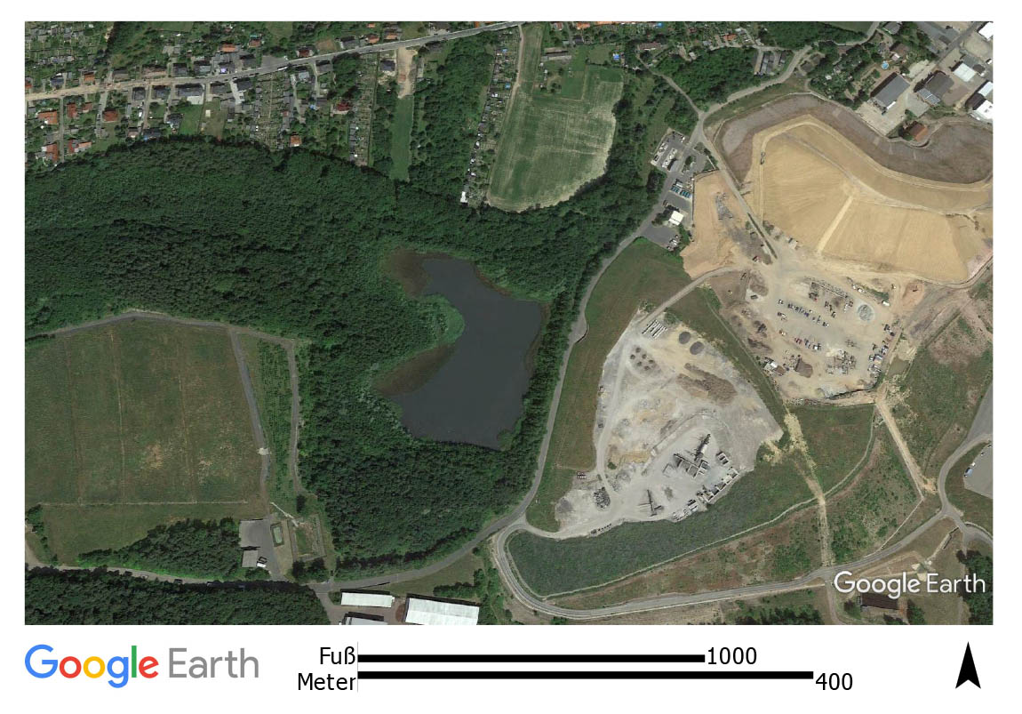
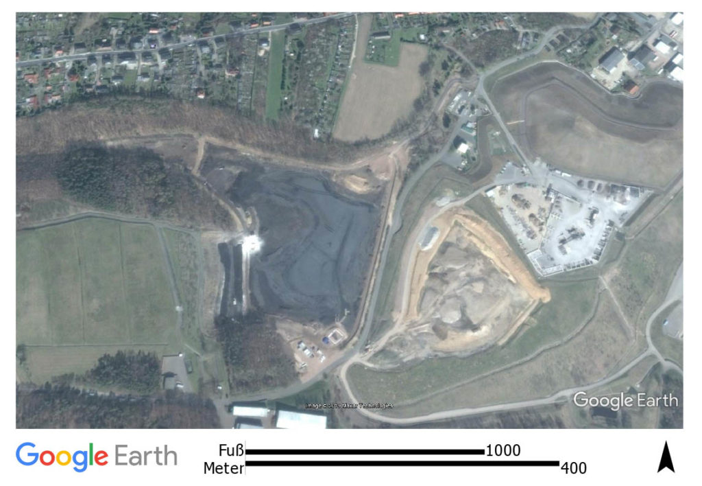
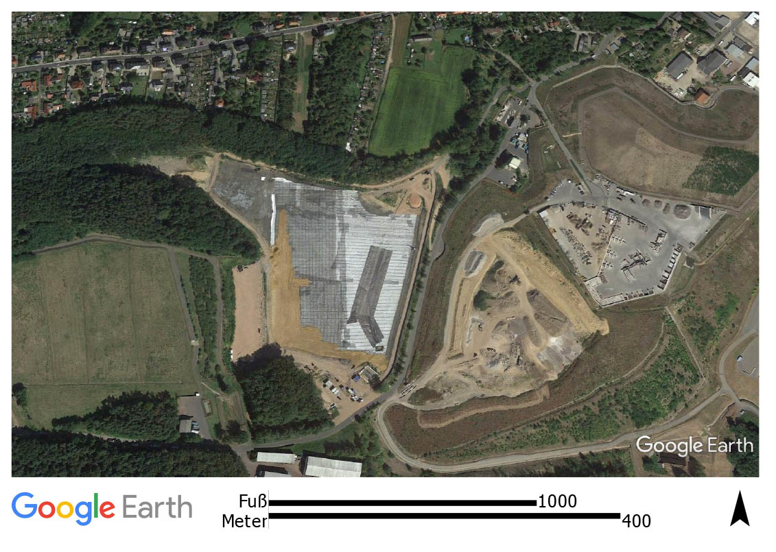
Figures 5a and 5b illustrate an aerial view of the site before and during the installation of the geosynthetics.
The installation was carried out by laying thin layers of soil with a thickness of approximately 12 inches (30 cm) and acting as load-distributing working surface; for this purpose, light machinery is recommended (Figure 6).
For the middle cover area, the same installation procedure as for the outer cover area was used, but vertical drains in the triangular grid of 4.9 feet (1.5 m) were also applied. The vertical drains were installed through the first geogrid and the nonwoven geotextile, and then the second layer of geogrid was installed on top.

The central area of the pond is characterized by fine-graded sludge with low bearing capacity that cannot be considered as a working area. In fact, because of the extremely soft sludge, great deformations could occur due to the placement of mineral layers. In this case, an additional reinforcement layer was required. For this purpose, a woven geotextile (Sefitec PP 80), which has a longitudinal and transversal tensile strength of 59,000 pounds-force per foot (80 kN/m), on top of the other geosynthetic layers was used as additional support to the bearing capacity. Here, the woven geotextile was installed as a single large panel sewed in situ and then pulled over the defined area to the outer region where it was then fixed.
The tensile strength of the geosynthetic reinforcement was determined by carrying out the stability analysis of the system. The design considers the verification of the bearing capacity of the combined system (soft subgrade and geosynthetics). This analysis enables the determination of the design tensile strength of the bearing layers while the actual tensile strength of the reinforcement (i.e., geogrids or woven geotextile) will be determined by applying reduction factors that take into account creep, installation damage, joints and connections, environmental chemical impacts, and dynamic effects, if present. The service life of the geosynthetics was set to 25 years since their use is supposed to be limited to the construction period. The most unfavorable conditions regarding loading will occur during construction of the cover while equipment is present and is applying forces to the system. The traffic loads were set to p = 1.2 pounds per square inch (8 kN/m²) and the soil thickness varied from 1 foot (0.3 m) in the first lift to 6.6 feet (2 m) in the final design phase. The design was performed according to Eurocode 7 for the temporary load case.
Since the tailings varied significantly according to the region of the pond, a very low undrained shear strength equal to cu = 0.44 pound per square inch (3 kN/m2) was chosen to characterize the tailings behavior in the whole pond.
Once the stability check is carried out, the dimensioning of the anchor trench was performed by verifying the analysis against the pullout and/or sliding of the geosynthetic reinforcement. In fact, the load of the cover soil is taken from the reinforcement, which in turn transfers it to the anchor trench that was accordingly designed to withstand the acting forces.
Conclusion
Pond 4 is a tailings pond in Freital, Germany, built in 1957 as a settling basin for residues of the uranium ore treatment of the Wismut company. In 2015 the remediation work, consisting of an impermeable cover system to close the impoundment and for subsequent landscaping, started. The construction of the cover system on top of the weak and heterogeneous tailings of Pond 4 has been made possible by the use of geosynthetics that provided the most economic and feasible solution. The selected geosynthetics separated and reinforced the weak subgrade, creating a safe and workable surface for the installation of the cover system. The conceptual design, the selection of the materials and the installation phases are fully described and can be used as reference for alternative solutions in similar projects.
References
Edil, T. B., and Aydilek, A. H. (2001). “Geotechnics of capping very soft wastes.” Proc., 13th Int. Conf. on Soil Mechanics and Geotechnical Engineering, Istanbul, Turkey, Vol. 3, 1,903–1,906.
Espinoza, R. D., Steier, W. M., and Steiner, M. (2012). “Construction of cover soil over soft sludge lagoons.” Proc., GeoAmericas 2012, Lima, Peru.
Koß, V. (1997). Eine Einführung für Studium und Praxis. Springer. 211–216.
Syllwasschy, O., Detert, O., Brokemper D., and Alexiew, D. (2007). “Special process techniques with project specified geosynthetics for sludge lagoon covers.” Proc., IS Kyushu 07, 5th Int. Conf. on Earth Reinforcement, Fukuoka, Japan.
Syllwasschy, O., and Wilke, M. (2014). “Sludge treatment and tailings pond cappings by the use of geosynthetics.” Proc., 7th Int. Congress on Environmental Geotechnics (7 ICEG), Melbourne, Australia.
Wismut GmbH website: www.wismut.de/en.
Zinck, J. (2005). “Review of disposal, reprocessing and reuse options for acidic drainage treatment sludge.” Canmet Mining and Mineral Sciences Laboratories, Natural Resources Canada, MEND Report 3.42.3.
Laura Carbone, Eng., Ph.D., is senior engineer with HUESKER in Gescher, Germany.
Ole Syllwasschy, Eng., is expert engineer with HUESKER in Gescher, Germany.
Lilma Schimmel, MSCE, P.E., is engineering department head with HUESKER in Charlotte, N.C.