 TEXTILES.ORG

New applications of geosynthetics are being found that form from overlaps of existing functions, such as protection, separation, filtration and drainage. One new geosynthetic product, the geosynthetic mattress ballast layer (GBL), was first implemented for an ore-processing waste facility protection application in 2015.
The GBL is a geotextile containment system that provides a tubular component interconnected with a geosynthetic mattress configuration that can be filled with waste product (HUESKER 2016). For the case study discussed in this article, contractors filled the GBL with industrial mineral waste, which is pumped to the facility in the form of slurry. However, in other applications the filling material could range from sand to concrete.
A further optimization is the addition of a nonwoven geotextile stitched to the exposed side-slope layers to counter ultraviolet (UV) degradation of the underlying woven geotextile. The case study project includes this optimization, as the ballast layers on the side slope take longer to be covered by the waste body.
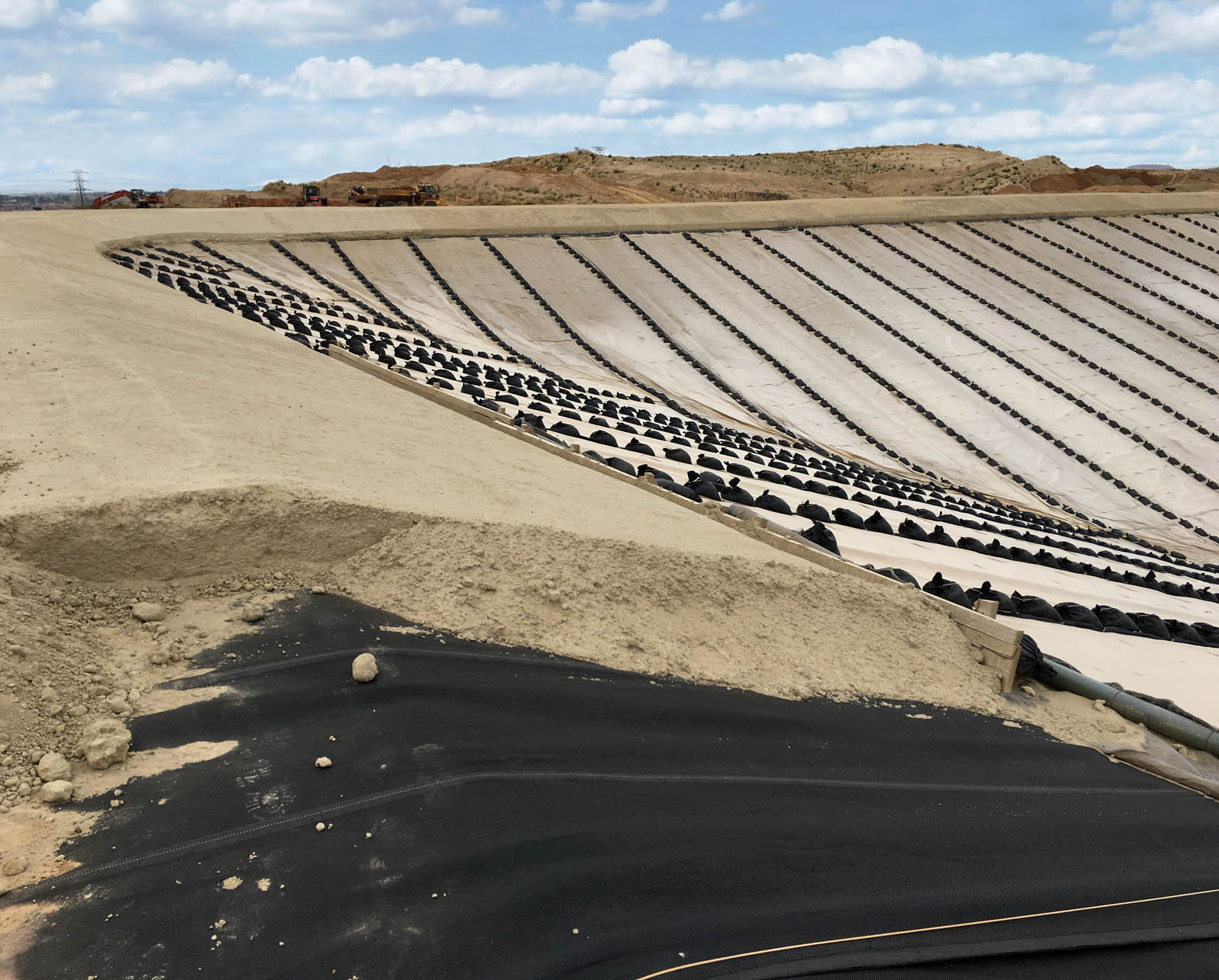
The main advantage of GBL is that the site waste product for which the waste containment facility is being constructed is also used to create the ballast layer itself (as part of a geosynthetic/waste composite structure), which has large sustainability benefits for ore-processing operations (Figure 1). It is also worth highlighting that site owners can consider carbon offsetting as part of their operations.
Previous research
Cilliers (2015) first introduced the GBL at the Landfill Conference and Exhibition in Tulbagh, Western Cape, South Africa. The idea behind the ballast layer was to create a protective layer above the primary geomembrane of a waste facility without using conventional methods of placing a typical ballast layer with heavy construction equipment. Nosko and Touze-Foltz (2000) found that placing the ballast layer in this way was the largest contributing factor to leakage due to damage of the primary liner.
The GBL needs to fulfill all the features of a conventional ballast layer, including protecting the primary geomembrane from mechanical and UV damage, applying a confining stress to ensure intimate contact between the primary geomembrane and the underlying clay layers, and ensuring that no folds, due to thermal expansion, are entombed in the primary liner during installation.
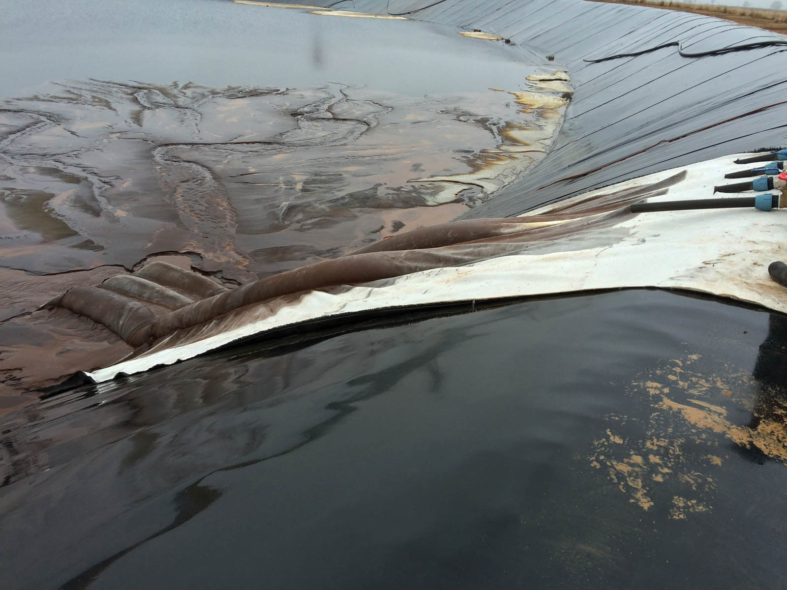
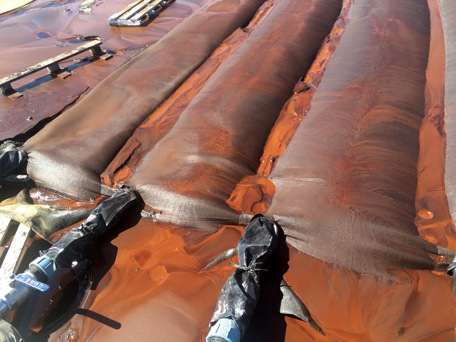
The GBL manufacturer for this case study has a long history of producing dewatering tubes made from woven geotextiles. The company also has an existing geotextile formwork product range that acts as a surface sealing system while protecting against erosion, mechanical damage and buoyancy, traditionally provided by concrete (HUESKER 2017). The manufacturer and the consulting engineers worked together to create a GBL prototype based on the dewatering tubes and the geotextile formwork product range (Figures 2 and 3). The GBL concept was then discussed and offered as an alternative to a confidential client in the early stages of constructing an industrial waste facility. The facility was planned to have a Class A liner system with a conventional cement-stabilized sand ballast layer.
The results were sufficiently promising for the client to request adaptation of the design using the GBL as the complete ballast layer for the new facility. The development of the prototype also resulted in essential information, such as expected shrinkage during filling, which was later used to size the overlaps on the ballast layer panel layout.
Sustainability
The term “sustainability” can be defined as “development that meets the needs of the present without compromising the ability of future generations to meet their own needs” (World Commission on Environment and Development 1987). Carbon dioxide (CO2) emissions are one of the main indicators of sustainability.
Several countries are setting sustainable low-carbon construction targets through governments or funding bodies (e.g., Asian Development Bank). The construction industry’s drive for sustainable practices focuses on reducing CO2, because CO2 curtailment contributes to national targets for lessening overall greenhouse gas emissions (Koerner 2016). Carbon footprinting techniques are used to establish the embodied carbon (EC) for a solution over set life cycle boundaries. A key component of any such assessment is the EC of the materials chosen for construction.
Appropriate geosynthetic solutions can improve the sustainability credentials of a construction project, such as the U.K.’s Waste & Resources Action Programme (WRAP), compared to traditional construction options. Following recent research in Europe (Raja et al. 2015), the accuracy and repeatability of assessing the EC of geosynthetics is improving. The GBL manufacturer undertook detailed analysis of its CO2 emissions through its Environmental Product Declaration (EPD) certificates developed for Germany’s Institut Bauen und Umwelt (2014, 2016a, 2016b), which provide life cycle analyses (LCA), including carbon usage, assuming a cradle-to-gate model. The EC can now be accurately calculated for certain geosynthetic products and solutions.
The GBL solution was compared against the conventional ballast layer (CBL) option. The CBL is comprised of an 11.8-inch (300-mm) thick (compacted) cement-stabilized sand layer. The sand is sourced and screened on-site to reach a uniform grading size. The purpose of this article is to compare EC for the two options and is based on a calculation carried out for a site in South Africa assuming a 2.47-acre (1-ha) area and is based on a cradle-to-end-of-construction comparison (EC values for the activities of production, transport to the site and construction). Other common activities for both the geosynthetic and traditional ballast solutions are omitted, as they cancel each other out with respect to comparison, and leaving them out simplifies the analysis. The activities accounted for in this case study are not exhaustive, and a more rigorous study may include country-specific values for South Africa and a more detailed breakdown of construction activities on-site.
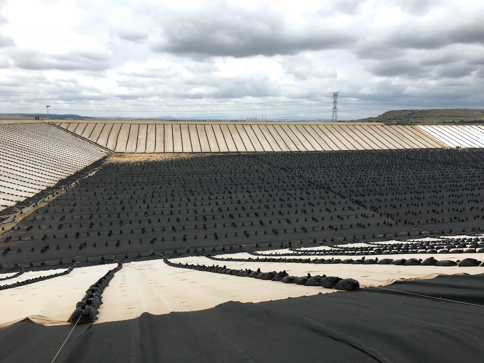
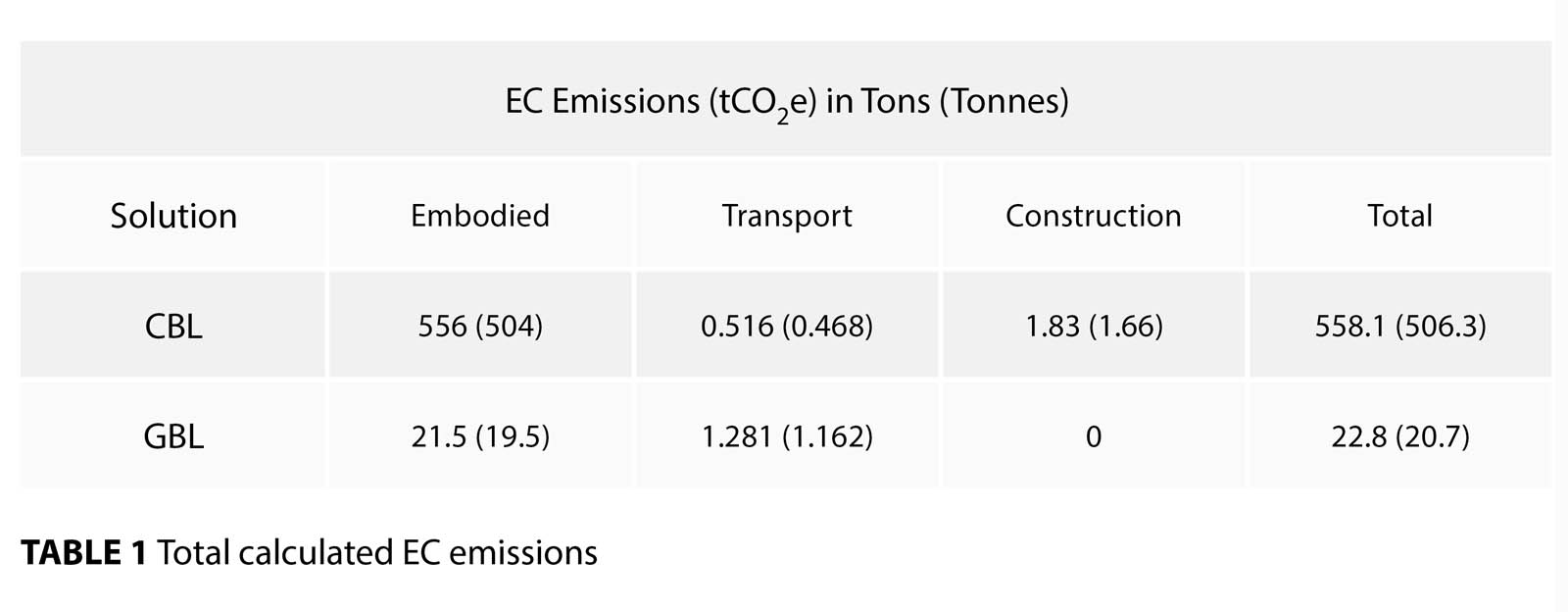 Table 1 provides a summary of the input parameters to allow EC comparison of the two ballast techniques (i.e., CBL and GBL). The value chosen for the geosynthetic EC was 3.0 kgCO2e/kg, which is based on an averaged value from the combined EPD certificates of the manufacturer, taking into consideration the amount of raw material used in the GBL (i.e., ~ 2.13 ounces/square foot [650 g/m2] for the three-layer material). This approach is conservative because the majority of the GBL used is a lighter-weight two-layer material, which does not include the sacrificial nonwoven upper geotextile layer (Figure 4). Therefore, the overall EC value of the GBL is likely to be lower for many future projects. It is worth highlighting that the study by Raja et al. (2015) stresses the significance of geosynthetic weight for sustainability, as the EC of the raw polymer accounts for approximately 80% of the final EC for a geosynthetic product at the gate (i.e., cradle-to-gate). Therefore, to achieve the optimum sustainability from a geosynthetic-based construction method, the geosynthetics must be used appropriately in design, and the polymer must be used efficiently, to produce a material that can achieve the design criteria (Koerner 2016). The calculation of the EC for transport (Equation 1) considers the distance traveled and the emissions of the transport mode.
C = (β (2D/α))/1000Q (1)
C = Total CO2 emissions per ton or tonne
D = Distance of transport in miles or kilometers
α = Fuel consumption in miles per gallon (U.S. or U.K.) of the semitruck or rigid heavy goods vehicle (HGV)
Q= Quantity of material in tons or tonnes
β = CO2 emissions per gallon or liter of fuel
In this case study, the construction plant emissions account for the main carbon-producing aspects of construction. For the GBL, the construction emissions are considered to be zero because any emissions produced due to the movement and positioning of the rolls of GBL with construction plant are vastly offset by the direct pumping of waste from the processing plant into the geosynthetic material to form the GBL.
Table 1 shows that the majority of EC emissions are produced during the production of the material used to form the ballast layer. For the CBL, if the sand had been sourced off-site, the EC emissions for transport likely would have also been high due to the bulk volume of the sand. The use of the waste product to fill the geosynthetic for this case study has a huge sustainability advantage. Further research on the advantages of carbon off-setting, related to the use of waste to form the ballast layer, would also be highly interesting.
Practical aspects
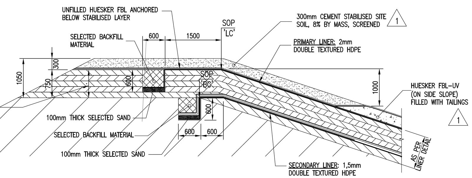
Due to the nature of the GBL in its current form, it needs to be manufactured to size. Therefore, the parties need to agree on a panel layout. This panel layout becomes the official plan from which the material list is generated. The material list is formed for two sections: basin and side slope. Each panel has a corresponding number and length. The panels are also placed in a specific sequence such that the delivery schedule of the panels can be matched to the construction schedule, if required. It is also important to note for side-slope panels that additional length was added before and after the required length of side slope to cater to anchorage and toe support (Figure 5).
As the manufacturer produces the panels to size, it is important to ensure strict adherence to the design of the facility during the earthworks stage and to ensure that the deviations are kept within small tolerances. The consequences of large deviations are that the panels will not cover the full footprint of the liner at installation and that additional panels will need to be supplied.
Knowing the method of installation before manufacturing also assists in packaging the bags such that deployment is carried out efficiently and correctly on-site; this outcome is enabled further by printing suitable labels on the GBL panels. This helps specifically for the side slopes where the nonwoven geotextile needs to face upward, and a certain length needs to be placed at the top of the crest for anchorage.
The GBL is planned to be filled with mineral waste slurry once the total installation is complete. It may take approximately five months from when the first ballast layer is installed to when the first ballast layer is filled with slurry. Therefore, the ballast bags need to be suitably held down against wind uplift during this period. With any application of geosynthetics, veneer stability should always be assessed to ensure there is negligible risk of slippage.
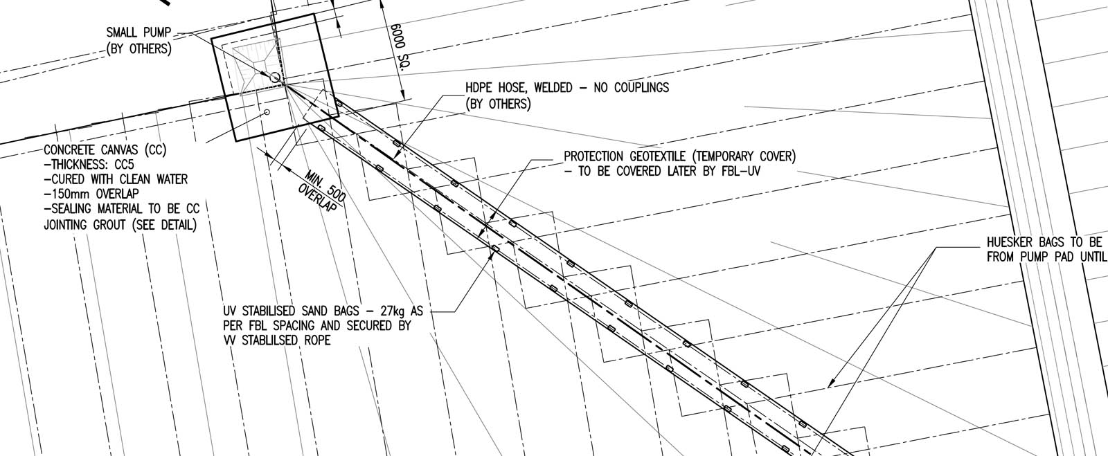
To fill the ballast bags, a sump is required at the low point of the basin. During the filling of the bags, continuous liquids are being generated from the de-watering process, which will drain to these low points. The liquid will begin to pool and will eventually need to be pumped out to another waste facility. Therefore, these low points need to be in place before the pumping of slurry into the ballast layer begins. Figure 6 illustrates in detail the pumping of a low point.
Conclusions
In the Cilliers (2015) paper, the author presents the costs of various ballast layer alternatives. When looking at the costs of storage savings per cubic foot or per cubic meter, the cost of the GBL compared favorably to the alternatives.
The comparison of GBL with CBL in this case study highlights that the GBL exhibits a very large savings (> 2,300%) in EC emissions versus the CBL. The use of waste product on-site to form the ballast layer within the geosynthetic largely accounts for this savings. Other advantages include the reduction in void space of the waste cell; i.e., the CBL would have taken up 11.8 inches (30 cm) of space, which is now filled with the same waste product that will be placed in the cell when construction is complete. For this project, the total storage capacity was increased by 3–4%, or 5,297,200 cubic feet (150,000 m3). The site owner/operator can also potentially offset carbon and gain carbon credits due to reusing waste in construction. This requires further research into South African guidelines on carbon credits and offsetting.
This case study shows the importance of considering several factors when selecting the optimum ballast layer, including, but not restricted to, project sustainability improvement, greater use of waste products, increased void space for waste depositing and overall project cost savings. The suitability of using GBL compared to CBL should be assessed on a project-by-project basis.
Charl Cilliers is a civil engineer and technical director with Jones & Wagener in Johannesburg, Gauteng, South Africa.
Melchior Briers is the market manager for mining at HUESKER Inc., based in Charlotte, N.C.
References
Cilliers, C. (2015). “The use of geosynthetics in the installation of ballast layers.” Proc., 2015 Landfill Conf. and Exhibition, Tulbagh, Western Cape, South Africa.
Department for Environment, Food and Rural Affairs. (2013). “Guidelines to DEFRA’s GHG conversion factors for company reporting.” London, U.K.
European Union Regulation (EU) No 305/2011. (2011). “Harmonised conditions for the marketing of construction products.” European Parliament, Brussels, Belgium.
Giroud, J. P., Pelte, T., and Bathurst, R. J. (1995). “Uplift of geomembranes by wind,” Geosynthetics International, 2(6), 897–952.
Hammond, G. P., and Jones, C. I. (2011). “Inventory of (embodied) carbon and energy (ICE),” Version 2.0. Department of Mechanical Engineering, University of Bath, U.K.
HUESKER. (2016). “Geosynthetic ingenuity in mining.” HUESKER Synthetic GmbH, Gescher, Germany.
HUESKER. (2017). “Incomat geosynthetic concrete mattress system for hydraulic engineering.” HUESKER Synthetic GmbH, Gescher, Germany.
Institut Bauen und Umwelt (Institute of Construction and the Environment). (2014). Environmental Product Declaration Number EPD-HUE-20140085-IAB1-EN. HUESKER Synthetic GmbH, Gescher, Germany.Institut Bauen und Umwelt (Institute of Construction and the Environment). (2016a). Environmental Product Declaration Number EPD-HUE-20160015-IAC1-DE. HUESKER Synthetic GmbH, Gescher, Germany.
Institut Bauen und Umwelt (Institute of Construction and the Environment). (2016b). Environmental Product Declaration Number EPD-HUE-20160014-IAC1-DE. HUESKER Synthetic GmbH, Gescher, Germany.
Koerner, R. M. (2016). “Geotextiles: From design to applications.” Woodhead Publishing, Sawston, Cambridge, U.K.
Koerner, G. R., and Narejo, D. (2005). “Direct shear database of geosynthetic-to-geosynthetic and geosynthetic-to-soil interfaces.” GRI Report 30. Geosynthetic Institute, Folsom, Pa.
Nosko, V., and Touze-Foltz, N. (2000). “Geomembrane liner failure: Modelling of its influence on contaminant transfer.” Proc., 2nd European Geosynthetics Conf., Pàtron Editore, Bologna, Italy, 557–560.
Raja, J., Dixon, N., Fowmes, G., Frost, M., and Assinder, P. (2015). “Sustainable construction solutions using geosynthetics: Obtaining reliable embodied carbon values.” Geosynthetics International, 22(5), 393–401.
U.K. Department for Transport. (2012). “Fuel consumption by HGV vehicle type in Great Britain, 1993 to 2010.” Table RFS0141, “Domestic road freight activity (RFS01).” https://www.gov.uk/government/statistical-data-sets/rfs01-goodslifted-and-distance-hauled.
World Commission on Environment and Development. (1987). Our common future. Oxford University Press, Oxford, U.K.
WRAP Project MRF116. (2010). “Sustainable geosystems in civil engineering applications.” Waste and Resources Action Programme, Banbury, U.K.
Hi Charl,
This is an interesting concept and I am glad I came across this article. Any chance you can send me the following paper?
Cilliers, C. (2015). “The use of geosynthetics in the installation of ballast layers.” Proc., 2015 Landfill Conf. and Exhibition, Tulbagh, Western Cape, South Africa.
Thank you,
Prabeen