 TEXTILES.ORG


Deep patch is a repair technique that has been widely used on low-volume roads in the Pacific Northwest as a cost-effective mitigation technique to address settlement and shallow landsliding of side-cast embankment fill slopes and natural slopes consisting of weak soils overlying stronger soils (Cuelho et al. 2012). A deep patch consists of a subexcavation typically in the range of 3-to-6-feet (1–2-m) deep backfilled with granular material and multiple layers of geosynthetic reinforcement that are vertically spaced from 6 to 12 inches (15–30 cm).
This article summarizes performance from three sites where a deep patch was used as mitigation over landslides that were larger and moving faster than traditional deep-patch applications.
The costs and environmental impacts associated with mitigation of large landslides are often outside the scope and budget of highway projects, especially on low-volume roads. Deep patches can be used to slow the development and propagation of roadway displacements over relatively fast-moving landslides.
State of practice for deep-patch design and construction
Most deep patches in the Pacific Northwest have been constructed to address settlement and shallow slumping of side-cast embankment fill slopes and natural slopes consisting of weak soils overlying stronger soils. In recent years, research has documented the benefits of multiple layers of closely spaced geosynthetic reinforcement, referred to as geosynthetic reinforced soil (GRS), when vertical spacing is less than or equal to 12 inches (30 cm) (Leshchinsky and Vulova 2001, Wu and Helwany 2001, Wu and Pham 2013).
Design procedures and key considerations are summarized in Collins 2015. Constructibility is a key component of the deep-patch design process; the layout of the deep patch is determined based on public and construction traffic considerations.
The state of practice for deep patches utilizes the GRS concept to create a composite structure. A deep patch typically has three or more layers of geosynthetic reinforcement at vertical spacings between 6 and 12 inches (15–30 cm). The authors have found that 6-inch (15-cm) vertical spacing is most cost-effective because it requires the least amount of excavation and backfill. Woven geotextiles, biaxial geogrids and uniaxial geogrids have all been used successfully.

Going-to-the-Sun Road, Glacier National Park, Glacier County, Montana
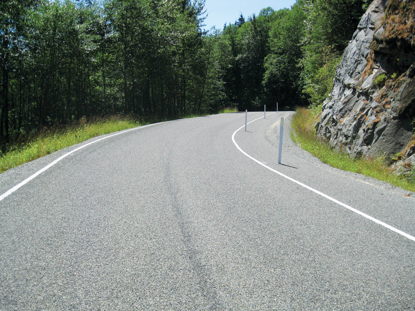
Going-to-the-Sun Road (GTSR) traverses along the northern edge of St. Mary Lake on the east side of Glacier National Park, Montana. During a repaving project in 1991, horizontal drains were installed at four locations as mitigation to landslides. During site visits in 2010 and 2011, pavement damage was observed at two of the four sites, indicating continued landslide movement. One of the landslide sites (referred to as Slide No. 1) appeared to be more active and had multiple pavement patches that had been placed since the 1991 project. Vertical scarps were as much as 1-foot (0.3-m) high on the shoulder of the road adjacent to the patches at Slide No. 1.
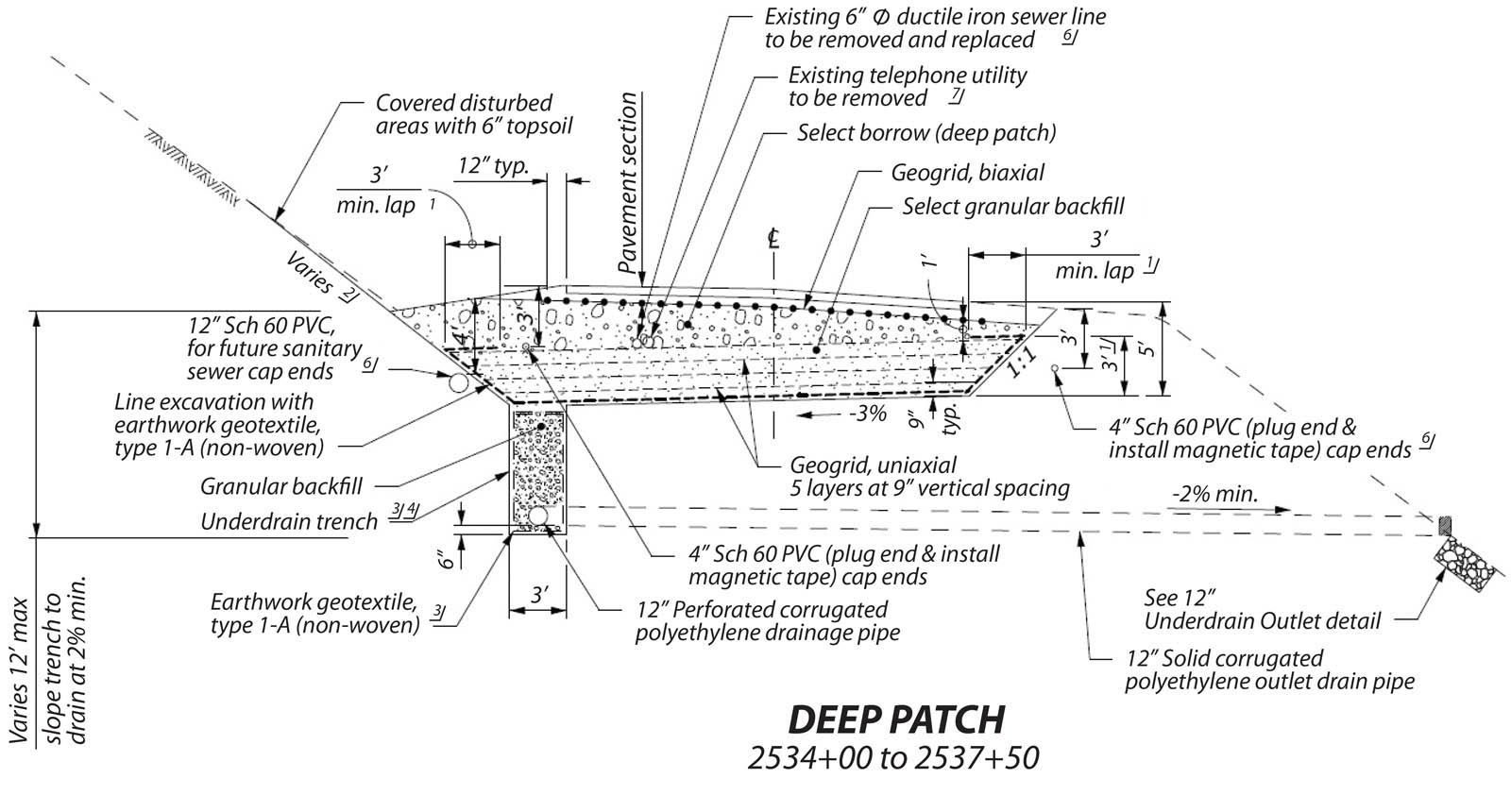
Deep patches and underdrains were recommended to mitigate the landsliding at the two sites (Collins 2012). The deep-patch reinforcement consisted of five layers of uniaxial geogrid placed at 9-inch (23-cm) vertical spacing (Figure 2). The underdrain extends as much as 12 feet (4 m) below the ditch line. The existing horizontal drains were jetted during construction.
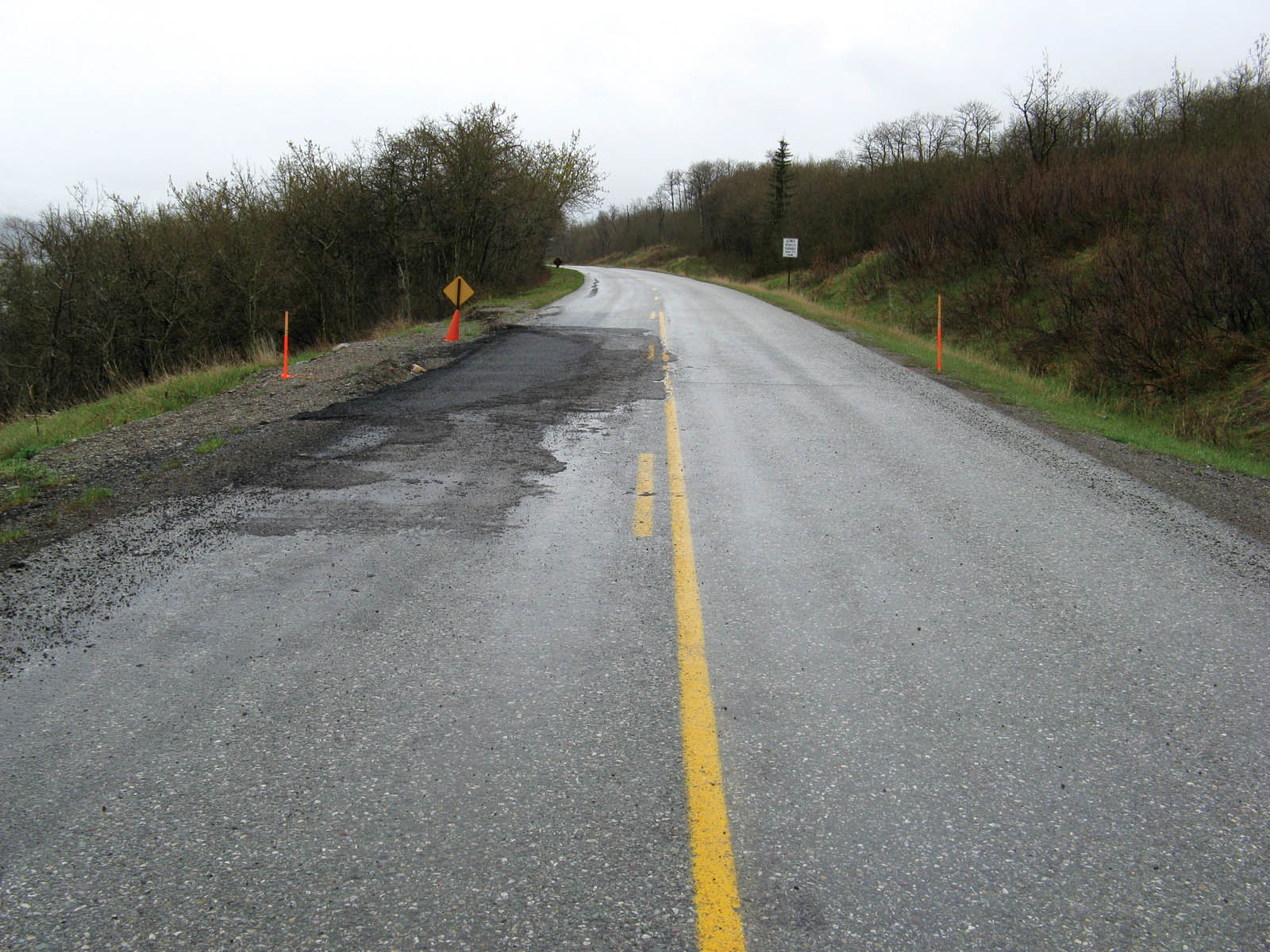
Figure 3a shows the road before construction. The GTSR deep patch was constructed in April 2014. Since construction, no additional pavement distress has been observed (Figure 3b).
Middle Fork Snoqualmie River Road, Mt. Baker-Snoqualmie National Forest, King County, Washington
Middle Fork Snoqualmie River Road (MFSRR) is east of North Bend, Washington, about 30 miles (48 km) east of Seattle. MFSRR provides recreational access to thousands of acres of wilderness areas in the Cascade Range. The Western Federal Lands Highway Division (WFLHD) of the Federal Highway Administration was the lead agency for reconstruction of the existing gravel road into a paved road. The 10-mile (16-km) long section of road had a history of instability at several locations. The average annual precipitation exceeds 100 inches (254 cm) in the valley, and roadway damage consisting of bank erosion, landsliding, debris flows and roadway overtopping has historically occurred along the road following heavy precipitation events.
Deep patch was recommended at 12 locations that were either exhibiting signs of instability or interpreted to be at a high risk for instability due to creeping slopes observed at those locations (Collins 2013).
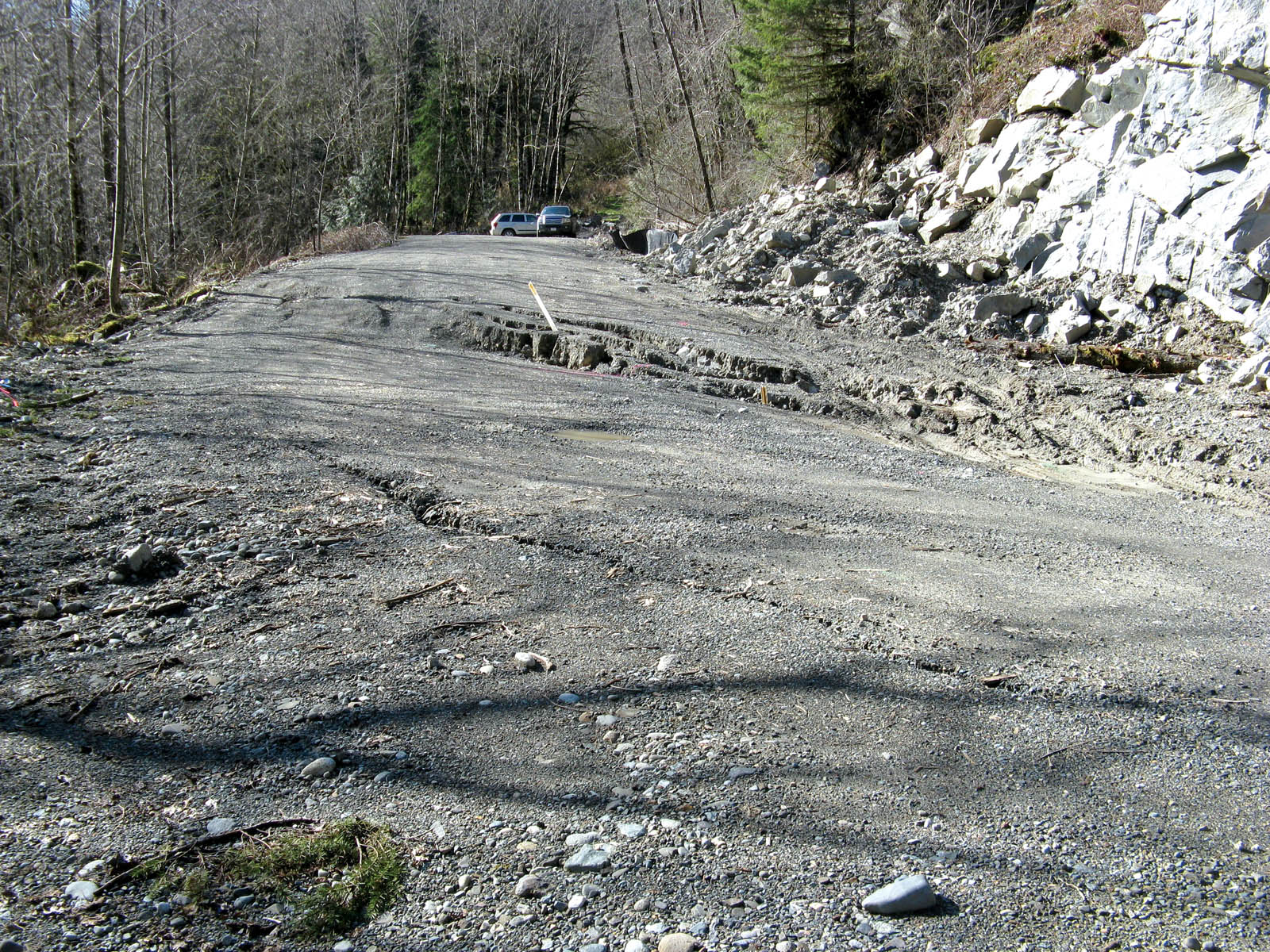
Two adjacent landslides, collectively referred to as the Milepost 10 Landslides, have a documented history of movement dating back to the early 1990s. These landslides were affecting about 2,300 feet (700 m) of the roadway, and movements in slope inclinometer casing were recorded at depths between 45 and 50 feet (14–15 m) below the ground surface. The landslide movements were attributed to heavy precipitation and runoff events, which also corresponded with river erosion at the toe of the landslides. The existing gravel surfacing was rather forgiving, but following high-precipitation events, a 1-to-2-foot (0.3–0.6-m) vertical drop would cross the roadway at one of the head scarp locations. Mitigation of these relatively large landslides was outside the scope of the WFLHD project due to the associated high costs and environmental impacts. Deep patch was used through this section to slow the development and propagation of cracking associated with future landslide movements. A chip seal was used for surfacing as a more flexible alternative to the asphalt concrete pavement used elsewhere on the project.
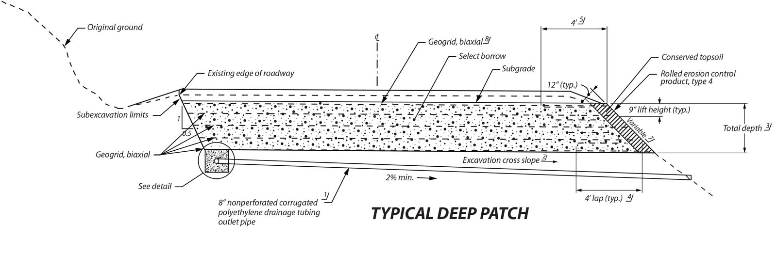
The typical deep-patch detail used on MFSRR illustrated both 3-foot (1-m) deep patches with five layers of biaxial geogrid at 9-inch (23-cm) vertical spacing and 4.5-foot (1.4-m) deep patch with seven layers of biaxial geogrid at 9-inch (23-cm) vertical spacing (Figure 4). The deep patch at the Milepost 10 Landslides was 4.5-feet (1.4-m) deep.
A U.S. Geological Survey gauging station near the Milepost 10 Landslides was used to develop a correlation between the occurrence of damaged sites in the project corridor with heavy precipitation events (Collins 2016). Damage was observed at the Milepost 10 Landslides in March 2015 following heavy precipitation events over the 2014–2015 winter (Figure 5a). The deep patch at the Milepost 10 Landslides was completed in May 2015, but not paved. During the winter of 2015–2016, multiple heavy precipitation events occurred, resulting in damage at other sites along the project, but no displacement was observed in the roadway at the Milepost 10 Landslides. The chip seal was placed in June 2017 (Figure 5b).
Agness Road MP 13, Rogue River-Siskiyou National Forest, Curry County, Oregon
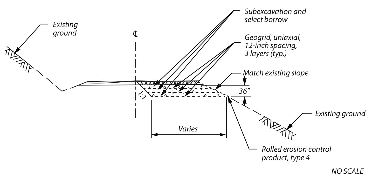
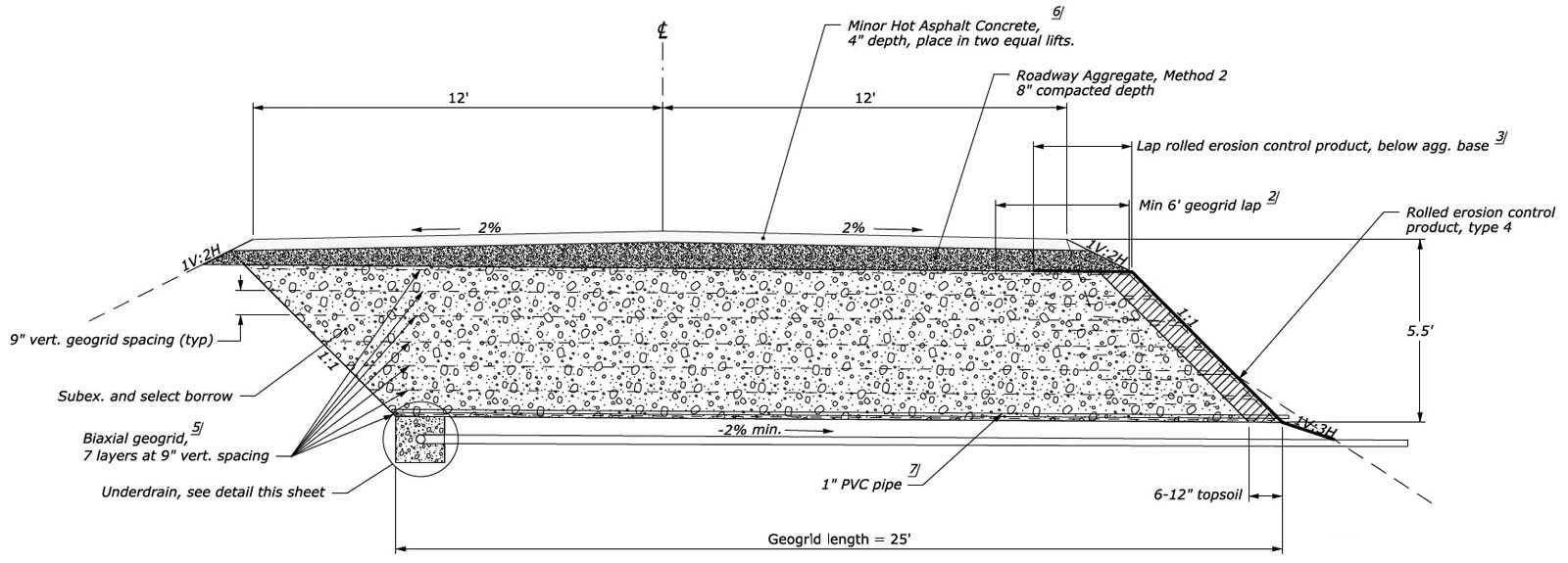
Agness Road (locally known as Jerry Flat Road) is a narrow two-lane forest highway through mountainous terrain that goes from Gold Beach to Agness, Oregon, in the southwestern corner of the state. In 2011 cracking and pavement distortion was observed at milepost 13.2. In September 2011 a half-width deep patch was constructed. The deep patch was 3-feet (1-m) deep, with three layers of geogrid at 12-inch (30-cm) vertical spacing (Figure 6). In 2012 the shoulder (outside the limits of the deep patch) dropped about 2 feet (0.6 m). The shoulder was rebuilt with a rock fill that same year. By 2013 the site had begun to move again, and distress was observed in the pavement. Another project was initiated to construct a more robust deep patch at the site. The new deep patch was 187-feet (57-m) long and 5.5-feet (1.7-m) deep with seven layers of biaxial geogrid with 9-inch (23-cm) vertical spacing and extended the full road width (Figure 7). An underdrain system was installed that extended 1 foot (0.3 m) below the deep patch. A pipe in the middle of the landslide was removed, and the ditch water was directed to another pipe outside the limits of the landslide.
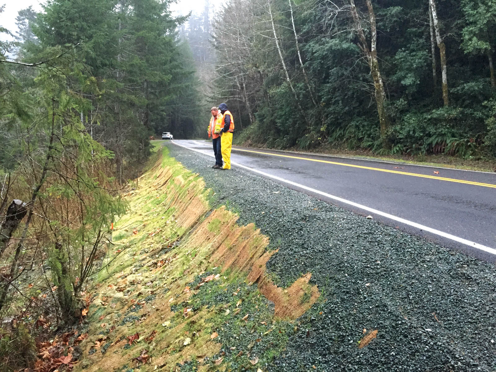
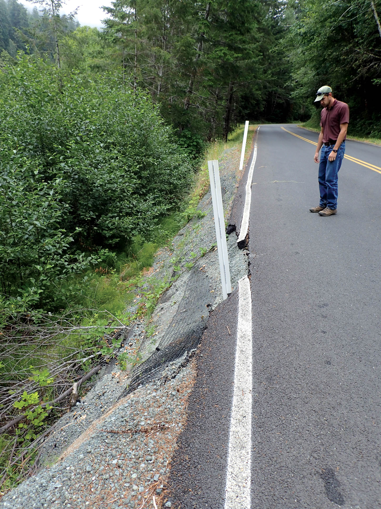
By September 2014 the roadway had displaced nearly 6 inches (15 cm) along the centerline, with the most significant displacement at the back end of the previously installed deep patch (Figure 8a on p. 20). The deep patch was constructed in October 2014 (Figure 8b on p. 20).
Since this site had an active history, it was identified as promising for gaining useful data on deep-patch performance through instrumentation. The instrumentation installed at the site included a horizontal shape-sensing instrument (Measurand ShapeArray) placed along the bottom of the deep patch, and linear variable differential transformers (LVDT) at 26 locations on the bottom and third layer (from the bottom) of the geogrid.
Using data loggers, the site has been monitored daily since construction. The ShapeArray plot indicates that the bottom of the deep patch has dropped approximately 42 inches (107 cm) over the 1,000-day monitoring period between October 13, 2014, and July 6, 2017. Each line in the ShapeArray plot is a measurement of the profile at a different point in time. The deformation is occurring in the outside 7 feet (2 m) of the cross section. The LVDT connected to the geogrid reinforcement measured strains on the order of 1% or less over the monitoring period.

Site observations have periodically been made during trips to download data from the data loggers. Continued landslide movement below the road was observed through a vertical drop that grew along the toe of the road embankment/deep patch. No deformation was observed in the road until August 2015 when hairline cracking was observed outside of the fog line. At that time, the ShapeArray indicated the bottom of the deep patch had dropped about 12 inches (30 cm) at the outside edge.
In January 2016 the cracking had not grown, but the road developed an approximately 0.5-inch (1.3-cm) dip where the cracking first appeared. At that time, the ShapeArray indicated the bottom of the deep patch had dropped about 15 inches (38 cm) at the outside edge.
In September 2016 the cracks had grown to about 1-inch (2.5-cm) wide and the dip was about 1-inch (1.3-cm) deep. The cracking was outside the fog line, and the dip was largely evenly distributed in the outside lane. At that time, the ShapeArray indicated the bottom of the deep patch had dropped about 28 inches (71 cm) at the outside edge.
In January 2017 the dip and cracks had both grown to about 2 inches (5 cm) total. At that time, the ShapeArray indicated the bottom of the deep patch had dropped about 30 inches (76 cm) at the outside edge.
In July 2017 the asphalt concrete pavement had fallen off outside the crack and the dip was still a total of about 2 inches (5 cm) (Figure 9 on p. 22). The ShapeArray indicated that total deformation was about 42 inches (107 cm) at the outside edge of the deep patch. We visually estimated that the ground in front of the deep patch had dropped more than 6 feet (1.8 m) in the time since the first fix in September 2011 and the July 2017 site visit.
Precipitation data from local weather stations were used to make a comparison between precipitation and movement of the landslide detected by the ShapeArray. Data was collected from three nearby weather stations (NOAA Climate Data 2017). Approximately 285 inches (724 cm) of precipitation fell in the area over the monitoring period. Most of the precipitation in the area usually occurs over the winter months from October through April.
Movement at the outside edge of the deep patch (25-foot [8-m] location) was plotted over time. Comparing the precipitation records and the outside-edge movement detected by ShapeArray, a strong correlation is seen between precipitation and landslide movement detected by the ShapeArray at the bottom of the deep patch.
Conclusions
Most deep patches in the Pacific Northwest have been constructed to address settlement and shallow slumping of side-cast embankment fill slopes and natural slopes consisting of weak soils overlying stronger soils. This article summarizes performance at three sites where a deep patch was used as mitigation over landslides that were larger and moving faster than traditional deep-patch applications.
The Going-to-the-Sun Road deep patch was installed at a site where more than 1 foot (0.3 m) of vertical deformation was observed during a site visit prior to construction. The deep patch consists of five layers of uniaxial geogrid at 9-inch (23-cm) vertical spacing.
Deep patch was used at 12 sites along the Middle Fork Snoqualmie River Road project. The road at the Milepost 10 Landslides site had historically dropped up to 2 feet (0.6 m) following heavy precipitation events. The deep patch at that location consists of seven layers of uniaxial geogrid at 9-inch (23-cm) vertical spacing and was covered with a chip seal surfacing to provide a flexible and more maintainable pavement section. No displacement was observed in the roadway at the Milepost 10 Landslides the winter after installation despite indications that heavy precipitation events that winter exceeded the threshold that would have historically resulted in displacement.
Deep patch was used on Agness Road at a site that had a history of landslide damage. The deep patch is 5.5-feet (1.7-m) deep with seven layers of biaxial geogrid at 9-inch (23-cm) vertical spacing. Instrumentation installed in the bottom of the deep patch indicates that the landslide dropped about 42 inches (107 cm) along the deep-patch bottom; however, a dip in the roadway above that location is less than 2 inches (5 cm).
These case histories all used deep patches with five to seven layers of geogrid at 9-inch (23-cm) vertical spacing. The deep patches were all successful at slowing the development and propagation of roadway damage caused by continued landslide movement. The Agness Road case history demonstrates that even when the deep patch is effective at reducing displacement of the roadway surface, some displacement should still be anticipated on the surface in applications to fast-moving landslides. This should be considered when deciding whether a deep patch is an appropriate application.
Acknowledgments
Instrumentation of the Agness Road deep patch was funded by the Coordinated Technology Implementation Program (CTIP). CTIP is a technology deployment and sharing program between the Federal Highway Administration Office of Federal Lands Highway and federal land management agencies with the purpose of identifying, studying, documenting and transferring new technology to the transportation community (Coordinated Technology Implementation Program 2017).
References
Collins, B. M. (2015). “Design considerations for deep patch embankment repair with geosynthetics.” Transp. Res. Rec.: Jour. of the Transp. Res. Board, No. 2473, 224–232. http://dx.doi.org/10.3141/2473-26.
Collins, B. M. (2012). “Final geotechnical report: Going to the Sun Road, Phase XII and XIII.” MT PRA GLAC 10(39) and MT PRA GLAC 10(40), Glacier National Park, Glacier County Montana. WFLHD Geotechnical Report, No. 06-12, Oct. 16.
Collins, B. M. (2013). “Final geotechnical report: Middle Fork Snoqualmie River Road.” WA PFH 29-1(1), Mt. Baker-Snoqualmie National Forest, King County, Washington. WFLHD Geotechnical Report, No. 10-12, Jan.
Collins, B. M. (2016). “Geotechnical site visit observations and recommendations.” WFLHD Geotechnical Memorandum, No. 10-16, March 7.
Coordinated Technology Implementation Program. (2017). http://www.ctiponline.org. (July 12, 2017).
Cuelho, E., Perkins, S., and Akin, M. (2012). “Deep patch repair phase I: Analysis and design.” Publication FHWA-WFL/TD-12-003. U.S. Department of Transportation.
Leshchinsky, D., and Vulova, C. (2001). “Numerical investigation of the effects of geosynthetic spacing on failure mechanisms in MSE block wall.” Geosynthetics Int., 8(4), 343–365.
NOAA Climate Data Online. (2017). https://www.ncdc.noaa.gov/cdo-web/search?datasetid=GHCND (July 25, 2017).
Wu, J. T. H, and Helwany, S. M. B. (2001). “Examining the effects of reinforcement in U.S. Forest Service deep-patch landslide repair technique.” Transp. Res. Rec.: Jour. of the Transp. Res. Board, No. 1772, 203–210. https://doi.org/10.3141/1772-25
Wu, J. T. H., and Pham, T. Q. (2013). “Load carrying capacity and required reinforcement strength of closely spaced soil-geosynthetic composites.” Jour. of Geotech. and Geoenviron. Engineering, 139(9), 1468–1476.
Brian M. Collins, P.E., is a senior geotechnical engineer with the Federal Highway Administration’s Western Federal Lands Highway Division in Vancouver, Washington.
Eli Cuelho, P.E., is a senior engineer at TRI/Environmental Inc. in Austin, Texas.
OWNER: National Park Service
CONTRACTOR: HK Contractors Inc., Idaho Falls, Idaho
GEOGRID SPECIFICATIONS
Uniaxial geogrid: Ultimate tensile strength > 4,800 pounds/foot (70 kN/m)
Nominal long-term tensile strength > 2,400 pounds/foot (35 kN/m)
OWNER: King County and Mt. Baker-Snoqualmie National Forest
CONTRACTOR: Active Construction Inc., Tacoma, Washington
GEOGRID SPECIFICATIONS
Biaxial geogrid:
Ultimate tensile strength > 1,850 pounds/foot (27 kN/m)
Tensile strength @ 2% > 550 pounds/foot (8 kN/m)
Tensile strength @ 5% > 1,100 pounds/foot (16 kN/m)
OWNER: Rogue River-Siskiyou National Forest
CONTRACTOR: Tidewater Contractors Inc., Brookings, Oregon
GEOGRID SPECIFICATIONS
Biaxial geogrid:
Ultimate tensile strength > 2,700 pounds/foot (39 kN/m)
Tensile strength @ 2% > 900 pounds/foot (13 kN/m)
Tensile strength @ 5% > 1,300 pounds/foot (19 kN/m)
Interested to know more about the products and process of Highway deep-patch geogrid applications to be introduced in our express highway roads throughout India