 TEXTILES.ORG


Part 1 of this series in the October/November 2017 issue of Geosynthetics demonstrated how the size, shape, pressure, and stresses and strains experienced by geomembrane bubbles surrounded by a confining fluid could be analytically estimated. Two different field case histories exhibiting the extremes of bubble sizes in ponds lined with 60-mil (1.5-mm) high-density polyethylene (HDPE) geomembranes were shown to corroborate the bubble sizes and pond depths estimated by the suggested analytical approach. Starting with an observed diameter of a bubble at the water surface and an assumed state of stress-strain in the geomembrane, Part 1 presented equations to estimate the depth of water surrounding the bubble that would exert hydrostatic pressures on the outside of the bubble to balance the calculated internal pressure needed to develop the assumed stress-strain state in the bubble. The method also predicts the bell-shaped profile of the entire bubble shape. This article, Part 2 of this series, discusses the often-used engineering approach of providing a gas-venting layer below the geomembrane to solve the bubble issue.
Underdrain design for gas venting
The term underdrain is used in many inconsistent ways in the literature. In this article, underdrain denotes a transmissive layer below a geomembrane. Because this article focuses on the technical aspects of relieving gas pressures below a geomembrane, the term is used for any drainage layer below a pond geomembrane regardless of whether it is a primary or secondary drainage layer in a single- or double-lined pond. It is left to the designer to understand the mechanics of the design and then adopt design-specific nomenclature for the project.
If it is desired to remove excess gas pressure from below the geomembrane by means of an underdrain, then the underdrain must be transmissive to gas. While this statement sounds obvious, what it implies is that the underdrain must be unsaturated, because gas will not flow through water from a practical point of view. Even for significant bubbles of concern, the internal pressures in the bubble may be as low as 0.07 psi (0.5 kPa), which corresponds to 2 inches (5 cm) of water depth. Nuisance bubbles, which may be quite large and voluminous but not yet creating any significant tension in the geomembrane, may have substantially less pressure. Thus, even a tiny amount of water head in the underdrain might be enough to prevent deflation and movement of unwanted bubbles. Only 5.5 inches (14 cm) of excess water head in the underdrain could block gas flow and allow gas pressure to build up to the point that it could start to compromise the integrity of the geomembrane. Saturation of underdrains can occur for several reasons, including elevated groundwater, infiltration of stormwater through the perimeter dikes and localized saturation due to leakage from above through defects in the geomembrane. If the pond design is dependent on deflation of gas bubbles via an underdrain, it is essential that a robust liquid underdrain system is provided that will maintain subsurface liquid levels below the level of the gas underdrain system. A lack of appreciation for the extremely low liquid heads, including those caused by leakage that could block a gas underdrain venting layer, is probably the chief cause of the unexplained malfunction of those types of systems.
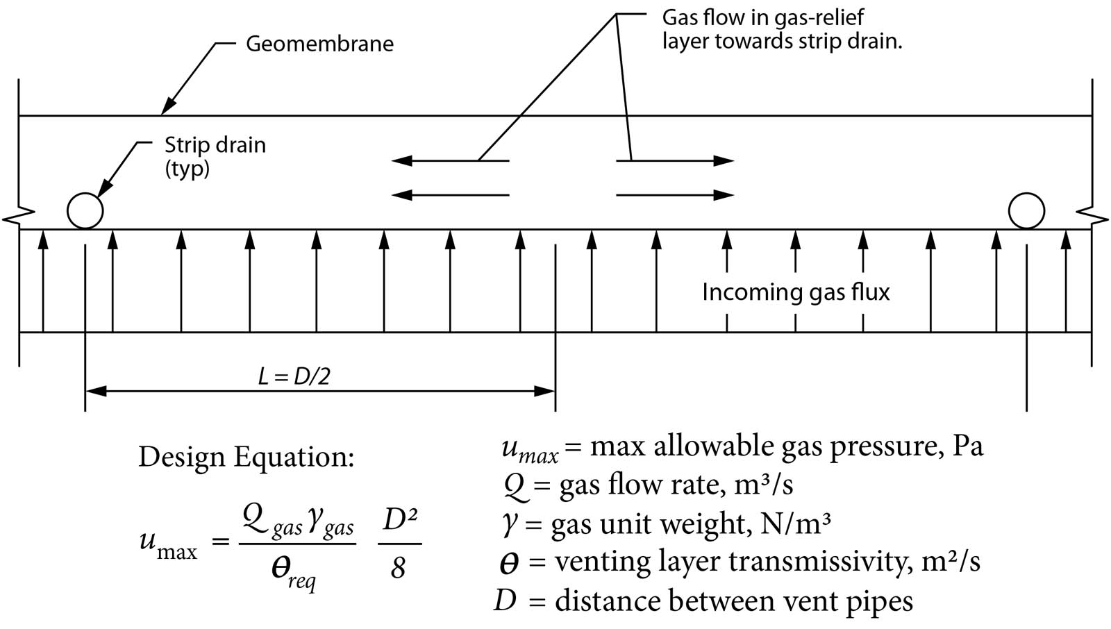
The approach for quantitatively designing the required transmissivity of a gas underdrain layer, including the spacing of piping and vents, is provided by Thiel (1998). While Thiel’s approach was developed to address gas relief below landfill covers, the methodology for gas relief below a pond liner would be identical. What is clear from that reference is that the unknown variable of greatest significance, as related to our topic, is the amount of gas flux that must be managed.
If the influx of gas to the underdrain is relatively consistent and can be estimated, then a project-specific maximum allowable pressure could be assigned to the problem, the required transmissivity of the underdrain layer could be calculated, and the required size and spacing of vents around the perimeter of the pond slope crest could be determined, according to the concept shown in Figure 2 derived from Thiel (1998). While Thiel (1998) provides a starting point for the gas influx at the base of final landfill covers, no such literature-based estimates are available for pond subgrades, and a site-specific determination would need to be made.
One potential design parameter could be the maximum rate of decrease in barometric pressure. For example, it may not be common, though not necessarily rare, that the atmospheric pressure could drop by 0.89 inches of mercury (3 kPa or 30 mb) over a period of one day. If the air that existed below the liner system was at the initially higher pressure, and the most immediate venting mechanism to equilibrate with the atmosphere was through the underliner venting layer, then the transmissivity of the venting layer that would be required to control the maximum differential pressure between the underliner and the atmosphere in the center of the pond could be calculated. While the details of this calculation exercise are beyond the scope of this paper, the tools are available to do it.
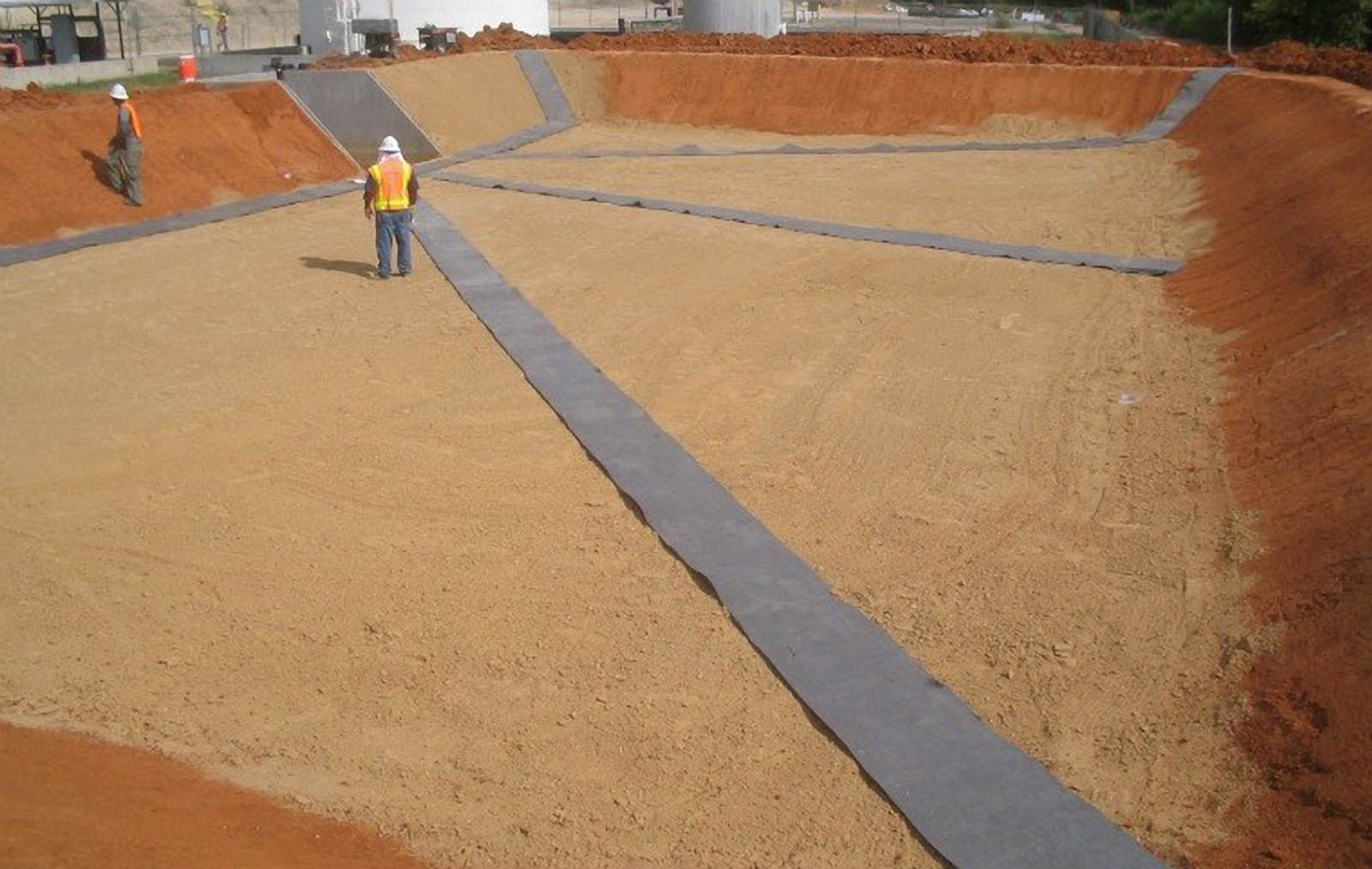
Since gas flux estimates below pond liners are very difficult to establish, design practitioners have developed “rule of thumb” practices. An example of such a practice that the author has seen more than once is that of providing under-drain strips, typically fabricated by cutting 2-foot (0.6-m) wide pieces from a geocomposite roll, on a spacing of 50 feet (15 m) below the geomembrane, connected to vents at the same spacing around the crest of the pond perimeter. An example of underdrain strip construction is shown in Figure 3. An early example of a similar design is described by Giroud and Bonaparte (1984). This rule of thumb may prove satisfactory in some cases.
If only a onetime gas deflation is necessary (e.g., initial air trapped under the geomembrane during deployment, as is occurring in the project shown in Figure 1 on pp. 36–37), and no new gas generation is anticipated, or gas generation is extremely slow (e.g., slow degradation of cellulose matter in subgrade), or gas generation is intermittent and of low magnitude (e.g., due to modest barometric or seasonal groundwater fluctuations), then a relatively low transmissivity material may be acceptable for the gas underdrain layer, provided there is no water present in the underdrain.
Thiel (1998) evaluated various materials for venting landfill gas below final covers. Laboratory testing of drained samples having moisture at field capacity indicated that standard nonwoven-needlepunched (NWNP) geotextiles with a mass/area of 16 oz/yd2 (540 g/m2) would have a gas transmissivity of approximately 3.9E-04 cfm/ft (6E-07 m2/s), which was about 30% lower than for a dry geotextile. Bouazza (2004) found similar low values of gas transmissivity for a standard NWNP geotextile with a mass/area of 15 oz/yd2 (513 g/m2) having a gas transmissivity of approximately 1.9E-04 cfm/ft (3E-07 m2/s) when dry, and approximately 40% lower when wet. These values would typically be too low for applications below a landfill cover, but could potentially function as a slow relief for onetime gas bubbles below a pond geomembrane. Thiel (1998) also tested a special coarse-fiber (15 denier) NWNP geotextile with a mass/area of 20 oz/yd2 (680 g/m2), which is not generally available but was manufactured specifically for the project, that had a higher wet gas transmissivity of approximately 1.3E-03 cfm/ft (2E-06 m2/s). The laboratory testing results were even less favorable for a fine sand material. Even though the sand material exhibited a saturated hydraulic conductivity of more than 6.5E-03 cfm/ft (1E-05 m2/s), and even though it would normally be approved by the state of New York (2016) landfill regulations for a “gas venting layer” below a final landfill cover, the amount of capillary-held water in a moist-drained condition resulted in a gas transmissivity of only about 1.3E-04 cfm/ft (2E-07 m2/s) for a 1-foot (0.3-m) thick layer. Thiel (1998) concluded that granular materials containing significant fine sands are not appropriate for gas transmissivity because of their tendency to have plugged pore spaces due to capillary water. For relief of a consistent influx of gas, robust transmissive underdrain materials—such as medium- to coarse-grained sands, gravels or geocomposites—are required in this capacity.
For very low gas-transmissivity materials, such as a NWNP geotextile, the local transmissivity could easily be overcome by leakage through a defect in the geomembrane, causing the geotextile material to be saturated and/or clogged by the sludge-laden water. Gas trapped in this area would not be able to vent through the saturated or clogged low-transmissivity material and may allow a slight bubble to form under the geomembrane. A slight bubble might serve to increase the orifice flow through the geomembrane defect because it would raise the geomembrane away from the subgrade. More leakage might elevate the liner even higher, causing saturation and/or clogging of the underdrain, creating a larger radius and attracting more gas to increase the size of the bubble, and thus this situation could potentially feed on itself. In most ponds of significance, leakage detection and management is important, and for this reason Thiel and Giroud (2011) suggest that all important exposed-geomembrane ponds be designed with a double-liner system containing a high-transmissivity leakage collection layer between the liners. Again, it is mandatory that the design ensure that the gas underdrain is maintained in an unsaturated state and is protected from potential saturation due to rising groundwater, stormwater intrusion or flooding due to leakage from above.
Lateral movement of gas bubbles
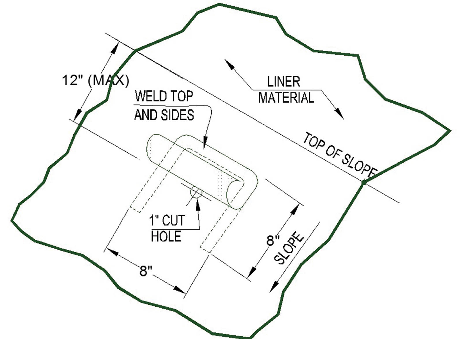
If the bubble pressure is not allowed to vent via an underdrain, then the bubbles must be forced to move laterally to the perimeter slopes. The required forces, and means to achieve this, will be the subject of Part 3 of this series. The gas would need to be vented up the perimeter slopes through vent holes through the geomembrane at the crest of the slope. A typical design detail of a simple flap vent is shown in Figure 4. It is important that vents be located near the crest above the maximum level of wave action to avoid allowing contained liquids from going into the vents and causing subgrade saturation and erosion. Gooseneck-style vents at the crest are safer in this regard.
Summary and recommendations
Part 2 of this series has discussed the approach and critical aspects for designing gas pressure relief layers below exposed geomembranes in ponds. For systems that count on a venting layer to relieve gas pressures, we have shown how important it is to have the groundwater, as well as leakage, to be maintained in a controlled drained condition. The required transmissivity of the gas-venting layer should be evaluated considering the potential for capillary water to block gas flow. If the underliner zone is flooded, then any gas underdrain will be rendered ineffective, in which case bubbles must be induced to move laterally by force. There are two means by which lateral movement of a bubble can be induced: manual pushing and by employing a bottom slope in the pond to create unbalanced hydrostatic pressures that cause the bubble to move upslope. A quantitative discussion of this issue will be the subject of Part 3 of this series, in the April/May 2018 issue of Geosynthetics.
REFERENCES
Bouazza, A. (2004). “Effect of wetting on gas transmissivity of nonwoven geotextiles.” Geotextiles and Geomembranes, 22, 531–541.
Giroud, J. P., and Bonaparte, R. (1984). “Waterproofing and drainage: Geomembranes and synthetic drainage layers.” Proc., 2nd Int. Symposium on Plastic and Rubber Waterproofing in Civil Engineering. Vol. 1, Session 3A, Liege, Belgium, June, 3A.1.1–3A.1.6.
State of New York. (2016). Title 6 of Codes, Rules, and Regulations, Part 360 for Solid Waste Management Facilities, Section 2.13 Landfill construction requirements, Paragraph p: Gas venting layer.
Thiel, R. (1998). “Design methodology for a gas pressure relief layer below a geomembrane landfill cover to improve slope stability.” Geosynthetics International, 5(6), 589–616.
Thiel, R. (2017). “Design of exposed geomembrane-lined ponds: Controlling uplifting gas bubbles—Part 1.” Geosynthetics, 35(5), 43–49.
Thiel, R., and Giroud, J. P. (2011). “Important considerations for leakage control of exposed geomembrane-lined ponds.” Proc., Sardinia 2011, 13th Int. Landfill Symposium.
Richard Thiel, P.E., is the president of Thiel Engineering in Oregon House, Calif.