 TEXTILES.ORG

Anchor systems are a vital portion of any erosion control program tasked with negating the effects of erosive forces on disturbed soils. Anchor systems are typically deployed in situations where a rolled erosion control product (RECP) is to be used as the primary erosion control measure. As more RECPs, especially high-performance turf reinforcement mats (HPTRMs), are being designed and specified to be used as systems in place of traditional hard armor for high-erosion-risk scenarios, anchor systems have been designed that can provide the pullout strength necessary to hold the HPTRM systems in place under worst-case conditions. However, there is no standardized test method used to determine a true apples-to-apples comparison of pullout capabilities for the different anchor system designs.
Background
The evolution of permanent erosion control technologies has led to a significant concentration on high-performance manufactured products that can be used to mitigate erosion and sediment loss in high-risk scenarios. This evolution has included the production and distribution of synthetic, woven RECPs that provide end users with quantitatively high-end material properties, including very high tensile strength, UV resistance, thickness and mass. Generally, these high-performance synthetic woven products are referred to in the product category of HPTRMs. HPTRM products are designed to be used in high-flow, high-erosion-risk scenarios, and they provide root reinforcement to the underlying root structure once the fundamental goal of establishing grass is achieved. Because these HPTRM products are designed to be used in high-flow, high-erosion-risk scenarios, the ability of the HPTRM to remain in intimate contact with the soil surface during a high-flow event is of the utmost importance. If the HPTRM loses contact with the soil surface because of flotation or tractive shear forces, seed migration and soil erosion can occur beneath the mat, undermining the fundamental goal of RECPs—that is, to encourage seed germination and vegetation establishment on a construction site, thus enhancing development of the root structure and holding soil in place permanently.
Traditionally, RECPs and other geosynthetics have been anchored to the soil surface with U-shaped sod staples in varying lengths, crown gaps and gauge thicknesses. These sod staples were initially designed to hold sod in place in areas that are rarely under the effect of erosive forces, such as home or commercial lawns, and become redundant once the root structure of the sod establishes. However, sod staples have traditionally been used throughout the industry as the essential technique for anchoring RECPs, including HPTRMs, to the soil surface. As the industry has pivoted to a focus on the use of alternatives to traditional hard armor, such as riprap, an increasing number of HPTRM systems have been introduced. Yet, there is a gap between the rapid adoption of HPTRM products and the relatively slow adoption of anchor systems specifically designed to act as part of the HPTRM system.
Because the combination of vegetation establishment and soil protection is the design criteria for HPTRM products, and because both vegetation establishment and soil protection are dependent upon intimate soil contact with the HPTRM, there must be assurance of intimate soil contact over the entire disturbed area under protection of the HPTRM. As such, manufacturers have brought to market a wide range of innovative anchoring devices designed to be used specifically with HPTRM materials. These mechanical soil anchoring (MSA) systems are designed to provide a stronger mechanical anchor point or points by which to ensure intimate contact between the HPTRM and the soil surface across the protected area, under the designed high-flow, high-erosion-risk scenarios.
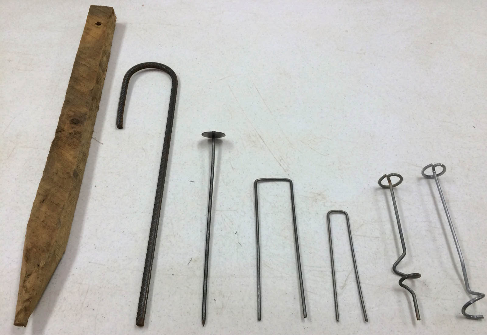
These anchor systems come in many shapes, sizes, and designs, including washer pins, deeply embedded anchors with strap or cable connectors anchored to the surface with a ratcheting plate, wood stakes, pins with proprietary designs and many other variants. These examples come in different sizes, gauges and strengths designed to provide graduated pullout strength performance when installed. However, there is currently no standardized test used to determine the pullout characteristics of each of these individual anchor types, sizes and designs.
Most available data on MSA systems are empirical or theoretical interpretations, derived from field trials, project-specific proof testing or mathematical theory. Design professionals are, therefore, unable to quantitatively determine which MSA systems should be used for specific HPTRM scenarios. In addition, without data representing a range of soil types and anchorage conditions, MSA system selection must be made without accounting for any potential change in anchor system behavior based on soil type, embedment depth or installation technique.

Full-scale anchor pullout testing
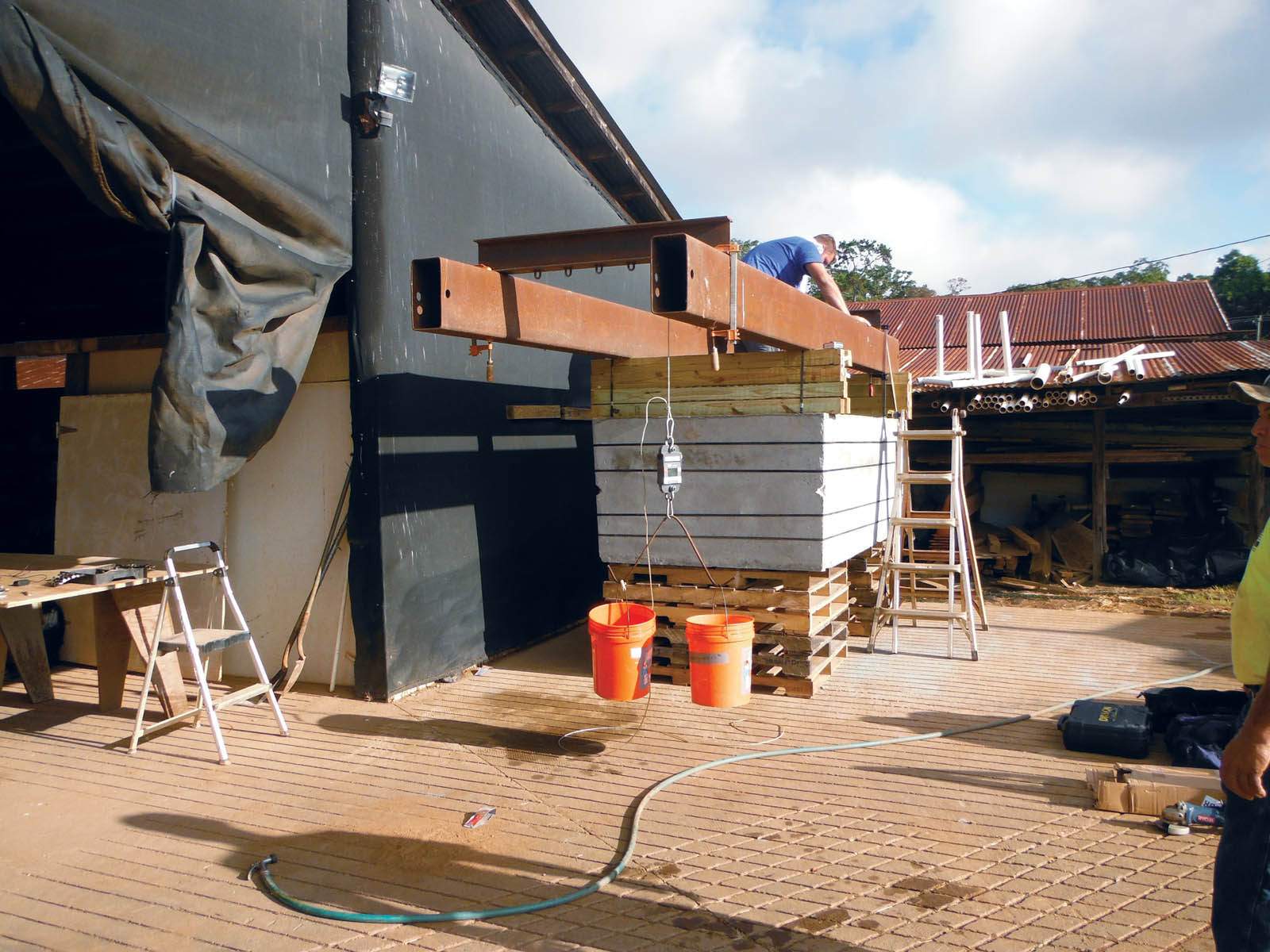
To answer the question “How much pullout resistance can I expect from this anchor?” a full-scale anchor pullout test apparatus was constructed in an effort to create a replicable, accessible, full-scale pullout test. The test apparatus consisted, in its most basic form, of a concrete container filled with compacted soil, steel support beams and a pulley system. The concrete container, a reimagined topless septic tank, allowed for a rigid, confinable area where soil could be verifiably compacted, and anchor installation and testing could be performed. The dimensions of the concrete tank were 8.6 feet (2.6 m) long × 4.2 feet (1.3 m) wide × 2.6 feet (2.6 m) deep. The steel beams of the apparatus acted as supports for clip-on points for the pulley system and provided the ability to conduct a pullout test of individual anchors without any physical contact with the soil surface, as would occur if, say, a tripod-and-winch system was used to create the pullout force.
Three soil types were used in this research program: loam, clay and sand. The loam soil was a sandy clay loam per the U.S. Department of Agriculture (USDA) soil classification system with a plasticity index of 14 per ASTM D4318, maximum dry density of 109.2 pounds/ft3 (1,749 kg/m3) per ASTM D698, and an optimum moisture content of 17% per ASTM D698. The density of the soil after placement and compaction was determined to be 88.3% of standard proctor density via the drive cylinder method per ASTM D2937.
The clay soil was a sandy fat clay per the USDA soil classification system with a plasticity index of 27 per ASTM D4318, maximum dry density of 103 pounds/ft3 (1,650 kg/m3) per ASTM D698, and an optimum moisture content of 21.4% per ASTM D698. The density of the soil after placement and compaction was determined to be 87.1% of standard proctor density via the drive cylinder method per ASTM D2937. The sand soil was a poorly graded sand per the USDA soil classification and was found to be nonplastic per ASTM D4318.
The soil had a maximum dry density of 113 pounds/ft3 (1,810 kg/m3) per ASTM D698 and an optimum moisture content of 12% per ASTM D698. The density of the soil after placement and compaction was determined to be 85.9% of standard proctor density via the drive cylinder method per ASTM D2937. Once soil placement, compaction and verification were completed, the apparatus was fully assembled.
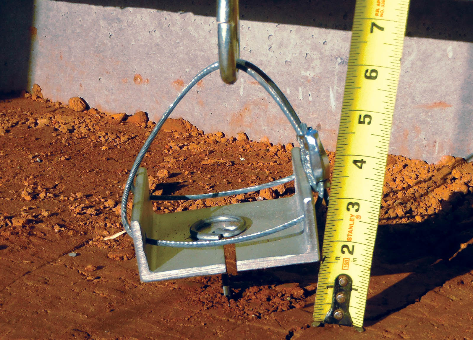
After the apparatus was fully assembled, the anchors to be tested were installed. The anchors tested varied in design and installation technique: from rebar J-hooks and washer pins that were to be driven into the soil with a hammer, to proprietary anchor products that required specialized drill bits for installation. Once the anchors were installed, a custom plate was placed under the head of the anchor (if necessary, to facilitate vertical pullout), and the pulley system was attached to the anchor or plate.
The pulley was a double-pulley block-and-tackle system that allowed for a 2:1 advantage from the load applied on one end of the system to the load imparted on the anchor. This advantage allowed for evaluation of higher-strength anchor products without the need for very high loads, expedited test time and alleviated safety concerns associated with large hanging loads. At the other end of the pulley system from the anchor was a vessel for adding load, connected to the pulley system by a calibrated load cell (Dillon EDjunior dynamometer). These vessels would be slowly filled with water, so that the anchor being tested would have a gradual and dynamic load applied, allowing for measurements to be made regarding both load and anchor-pullout distance in inches/centimeters.
As the load was applied to the anchor, measurements of pullout distance from the soil surface and the associated applied load would be recorded at ½ inch (1.3 cm), 1 inch (2.5 cm) and complete anchor pullout. The theoretical justification for taking pullout measurements at various levels of displacement is simple: There is currently no standard definition for pullout. One must interpret if pullout refers to the point at which an anchor initially moves from its as-installed position, or, on the other extreme, if pullout is defined by a complete removal of the anchor from the soil, or if it is somewhere in between. This procedure was repeated on all anchors tested in this program. The program discussed in this article consisted of pullout testing via the method described previously based on the following generically identified anchors:
- TA1 (proprietary anchor)
- TA2 (proprietary anchor)
- rebar J-hook 18 inch (46 cm)
- rebar J-hook 24 inch (61 cm)
- washer pin 12 inch (30 cm)
- washer pin 18 inch (46 cm)
- washer pin 24 inch (61 cm)
- 1.5 inch × 1.5 inch (3.8 cm × 3.8 cm) wooden post
- EA 10 inch (25 cm) (proprietary anchor)
- 8-inch × 1-inch × 8-inch (20-cm × 2.5-cm × 20-cm)—8-gauge staple
- 6-inch × 1-inch × 6-inch (15-cm × 2.5-cm × 15-cm)—11-gauge staple
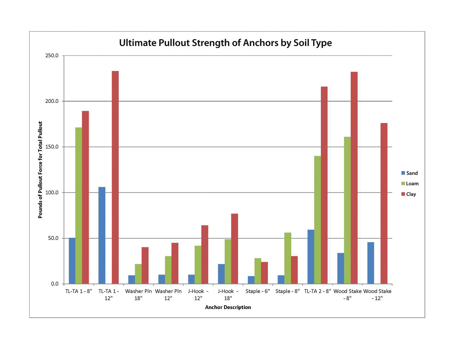
These anchors were chosen to represent a cross section of commodity and proprietary anchor styles used on construction sites to anchor HPTRM materials. The majority of the anchors tested via the method described above did not experience incremental pullout at ½ inch (1.3 cm) and 1 inch (2.5 cm), and instead would experience full pullout or full anchor removal from the soil. In these cases, only the load at full anchor removal could be recorded. The load and displacement was recorded and tabulated in Microsoft Excel and used to create the graphical representation. The data seems to show a clear hierarchy of anchor-system performance. Calculated pullout strength of the tested anchors ranged from 10 to 320 pounds (4.5–145 kg). This range represents the large difference in performance between product designs, and, arguably, also represents a quantifiable difference in performance of products of the same design, but different sizes.
The testing program described in this article seems to have objectively demonstrated clear, quantifiable performance differences between anchor systems of different designs and sizes. One anomaly did occur during the testing: The pullout strength of the washer pin–design anchors did not increase with an increase in anchor size or embedment depth, as occurred with other anchor systems designs that were tested at different sizes and embedment depths. This anomaly could be attributed to the fact that only 10 replicate pullout tests were completed on each anchor design and size, and could potentially be reconciled with further study.
As previously discussed, these results are only representative of anchor system performance in the particular soil type and compaction conditions used for this test program, and therefore are limited in scope. However, initial results seem to provide justification for further investigation of anchor performance using a full-scale standardized testing procedure. In addition, the results of this test method seem to pass the commonsense test of providing definable performance differences based on product design and size, therefore, at least preliminarily, providing validation for the test method, test apparatus construction and data interpretation methodology utilized in this test program.
Conclusions
The use of HPTRM materials has led to a need for anchor systems that can provide the appropriate mechanical soil anchorage under high erosion-risk scenarios. As such, manufacturers have developed proprietary anchor designs that theoretically provide the necessary pullout strength and performance. However, there is currently no standardized test method available to determine, quantifiably, the pullout strength and performance of these MSA systems. The test program described herein was designed to provide a relevant full-scale performance test of anchor pullout strength under defined, documented and replicable conditions. The results of the test program seem promising. Further, the results provide justification for further study and development of a standardized test method based on the program and methodology discussed in this article.
James E. (Jay) Sprague, a Certified Professional in Erosion and Sediment Control, is the laboratory director of TRI Environmental’s Denver Downs Research Facility in Anderson, S.C.
Joel Sprague is a long-time member of the senior technical staff of TRI Environmental in Austin, Texas, specializing in the research, development, and application of geosynthetics, plastic pipe, and erosion and sediment control technologies.
All photographs and illustrations courtesy of the authors.
This was a very useful article. Here in Australia, Cirtex get involved in delivering Platipus Anchor Systems & Solutions and would agree that people or specifiers do not pay much or enough attention to type of anchor or load verification with erosion matts in severe inland & coastal area applications. At least with Platipus we have tools to load verify and there is science behind the anchor load determination with Terzaghi & Skempton soil theories. Many thanks for this article it was interesting – Dave Markham
My professional Geotechnical Engineering experience with clay slopes, PI from 15 to 35, is
that over the long term (years, not minutes) the behavior of the soils will yield and deflect. Be careful at applying a several minute test to a long term installation. Some clay soils will also corrode bare steel. Long term performance is difficult to come by except by lawsuit experience.
robertrogersge@aol.com
Anchor testing should be performed with the load applied perpendicular to the direction of the axis of the anchor. Anchors are most often used to counteract the forces of gravity as they work upon the geocell on a slope. The anchors are driven perpendicular to the slope and the force upon the anchor is parallel to the slope, not in the direction tested in this study.
There is some relevance, because as an anchor slices through the soil and the anchor begins to fail… A small component of the force translates to the axis of the anchor. But more importantly, any anchor that connects to the bottom of the wall of the geocell will be overrun as the geocell/infill mattress slides right over the top of the connection.
The extremely small diameter of wire pins and wire spiral products lead to bending of the anchor systems. The J-hook is not an acceptable solution due to the difficulty of driving them into the ground as the top of the J does not align with the axis of the remainder of the pin (leading to frustration by crews) and the J-hook shown in the image on this report is not the standard 1/2 inch rebar but appears to be a smaller diameter as well.
We recommend the ATRA stake clip over 1/2 inch rebar or better yet the ATRA speed stake. These products produced by Presto Products have been proven superior on thousands of installations. https://www.prestogeo.com/products/soil-stabilization/geoweb-atra-accessories/atra-anchor/
Another important factor to consider is the number of stakes required. My understanding is that the spiral two-piece solution requires an order of magnitude more units to compensate for its reduced holding power.