 TEXTILES.ORG

Introduction
Since the late 1800s, coal has played a leading role in U.S. production of electrical energy. Coal-fired power plants have provided reliable electrical power from the earliest days when power plants were run with hand-fed coal to heat boilers to produce steam. The introduction of pulverized coal led to improvements in the electrical-generation process by providing higher combustion temperatures, improved thermal efficiency, and a lower requirement for excess air for combustion.

In a typical coal-fired process, the heat of burning coal turns water into steam, which then drives turbine generators to produce electricity. This process starts when a power plant burns pulverized coal to produce steam; then the pressure of the steam drives the turbine shaft blades of a generator to produce electricity. The steam is pulled into a condenser where steam is converted back into water to be used repetitively in the facility.
The waste by-products created by this process have presented a challenge. In response, utility companies have continuously worked on innovations to uncover methods to burn coal more cleanly. The by-products are in various forms like fly ash, bottom ash, boiler slag, and flue gas desulfurization (FGD) material. The combination of these waste by-products is generally called coal ash, and coal ash is one of the most voluminous industrial wastes generated in the U.S.
Fly ash is primarily silica produced during the burning of pulverized coal, and it has a very fine, powdery consistency. Bottom ash forms in the furnace base and is a coarse particle that is too large to be carried up into the smokestacks. Boiler slag is molten bottom ash, and FGD is leftover material from the process of reducing sulfur dioxide emissions.
The environmental concern of coal ash waste by-products is that the ash contains many different types of contaminants that could pollute the environment. As a result, coal-fired power plants seek to reuse coal ash to reduce greenhouse gas emissions, landfill space, and virgin material costs.
The Environmental Protection Agency’s comprehensive set of requirements addresses the risks from coal ash disposal, such as leaking of contaminants into groundwater, blowing of contaminants into the air as dust, and the catastrophic failure of coal ash surface impoundments. In April 2015, the Final Rule for Disposal of Coal Combustion Residuals from Electric Utilities was published in the Federal Register under 40 CFR Part 257. This rule was followed by the publication in the Federal Register of the Effluent Limitations Guidelines under 40 CFR 423 in November 2015. As of April 12, 2017, EPA administrator Scott Pruitt postponed compliance dates under the Final Rule pending judicial review.
Geotextile tube dewatering technology
Geotextile containers have been used since the 1960s as shoreline protection in marine and river structures, such as breakwaters, dikes, artificial islands, and jetties. Over the years, this technology has transferred into the dewatering of wastewater with the aid of chemical conditioning. There are three basic stages to dewatering with geotextile containers: confinement, dewatering, and consolidation. The specially engineered textile from which the geotextile containers are fabricated provides confinement of the fine solids inside the container while allowing water to permeate through the textile. As the water drains, the solids continue to densify inside the geotextile container, and the volume inside the container continues to consolidate over time.
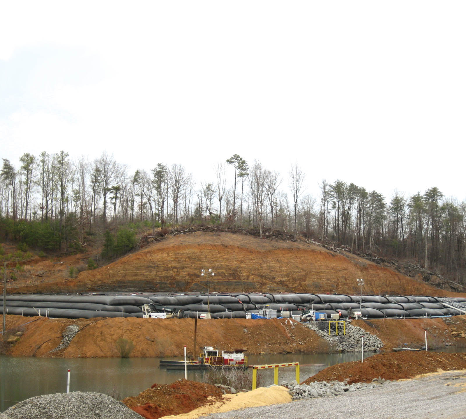
A dewatering cell, as shown in Figure 1, must be constructed to hold the geotextile containers. In most cases, the available area for construction of a dewatering cell is limited, but geotextile containers can be manufactured in many configurations and sizes to maximize the available footprint. Creating a slight grade with the slope in the length direction of the geotextile containers promotes drainage of the filtrate for better collection. An advantage of geotextile containers is that they can be stacked in a pyramid configuration several layers high depending on the consolidated characteristics of the dewatered solids.
This cell has an impermeable membrane installed to help control the volume of effluent that drains through the containers. Typically, the effluent is returned back into a body of water and can sometimes be directly discharged if the filtrate quality meets reporting limits. The CCR slurry can be dredged or pumped directly into geotextile containers.
If the flow of CCR slurry is extremely high, a manifold system can be installed, which allows multiple containers to be filled at one time to maximize dredging output. The primary feature of a geotextile container is to retain solids and contaminants while permitting effluent to drain through the pores of the woven engineered filtration textile. During all phases of the dewatering process (confinement, dewatering, and consolidation), the filtration textile must provide excellent tensile properties, efficient effluent drainage, and effective retention of solids to guarantee optimum slurry dewatering.
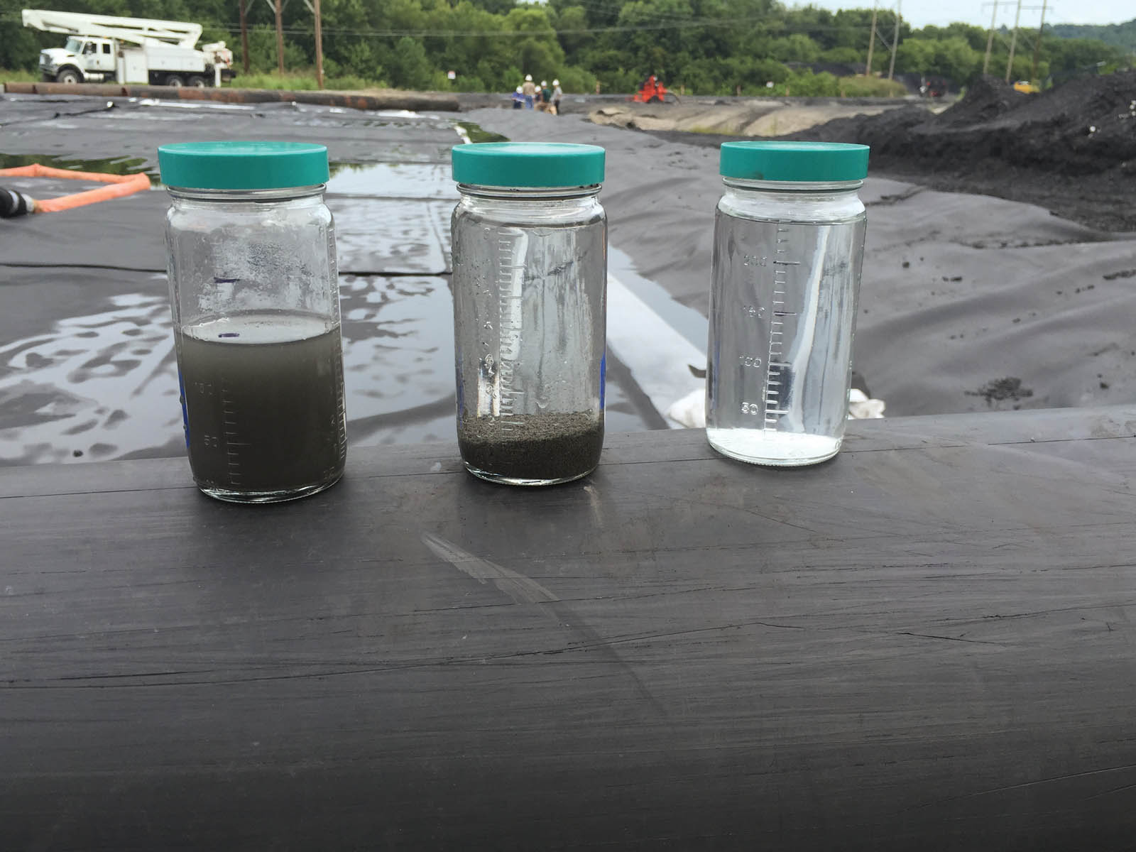
The filtration properties of the engineered textile permit the containers to capture the solids while water drains out. The moisture will continue to filter out and solids will continue to dry over time, promoting more volume consolidation. Using the appropriate polymer for chemical conditioning will allow for the solids in the wastewater stream to create an agglomeration and release free water for drainage. Figure 2 shows typical results of geotextile container dewatering.
Chemical conditioning optimizes the dewatering performance of geotextile containers, increasing the dewatering rate, improving effluent quality, and achieving higher dry mass. The chemical conditioning of the wastewater occurs before the slurry is pumped into geotextile containers to accelerate dewatering.
Once the solids are fully consolidated or have met minimum requirements for transport, several options are available for disposal. Typically, after consolidation, the geotextile containers can be cut open, and the solids can be transported to a landfill or land applied. In some applications, the containers can be buried in place, allowing the dewatering area to be reclaimed.
Coal ash management
By incorporating geotextile tube technology, coal-fired facilities can dewater and contain CCRs using specially engineered textiles that retain the solids inside geotextile tubes while releasing the clear water through the fabric pores. This technology can be utilized in the operation of existing surface impoundments, efforts to beneficially use consolidated ash, and the continued operation of coal-fired operations by direct sluicing the daily flows from the plant into geotextile tubes.
In particular, geotextile tube technology can provide an alternative to applications involving remediation and clean closure of impoundments, beneficial use of dewatered CCRs, direct sluicing, and providing structural containment for paste.
Projects involving the remediation and clean closure of surface impoundments require the hydraulic removal of CCRs to geotextile tubes, where the solids are retained inside the tube and effluent flows through the pores of geotextile fabric.
Removing the ash from the surface impoundments helps protect ground-water and shields the impoundment from external events like flooding, erosion of ash piles, and seismic events. Another advantage of geotextile tubes is containment of the ash to mitigate dust issues, which can help limit these effects in nearby communities.
The CCR material found in surface impoundments can include fly ash, bottom ash, slag, and other by-products. If the material requiring removal has coarse properties, then typically such CCRs can be dewatered without the aid of chemical flocculants. If the material composition is made up of very small fines, the addition of chemical flocculants could improve the overall utility of geotextile tubes. These chemical flocculants help bind together the small fines to become larger particles that can be retained inside the geotextile tubes; they also help the particles release chemically bound water.
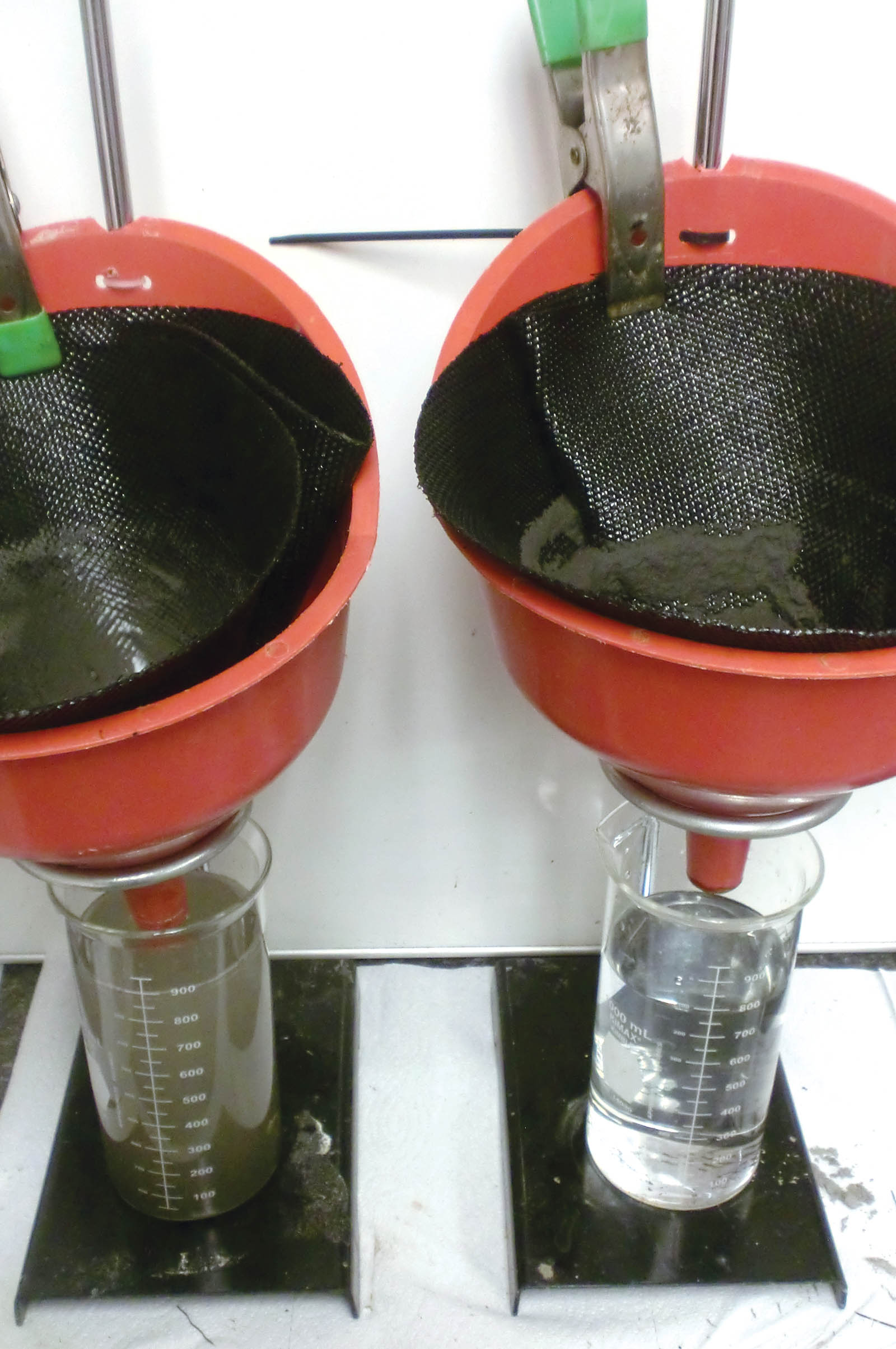
Extensive polymer bench testing must be conducted during the design phase to evaluate the proper chemical flocculants and dosage rates required. In Figure 3, the funnel on the left is in situ CCR slurry, and on the right is a properly chemically conditioned CCR slurry. The beaker below the funnel provides insight into the clarity of the effluent water, and the consolidated CCR solids are shown contained on the top side of the engineered textile.
These small-scale bench tests, like the pillow bag test (ASTM D7880), help predict the achievable dewatered solids attainable over time. Not only can the achievable dry cake solids be predicted, but this test also allows for assessment of the effluent water to determine if discharge criteria can be met.
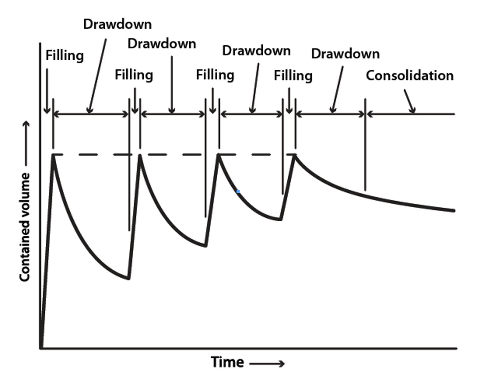
The material nature of the CCRs will determine the repetitive cycles of filling and dewatering required to consolidate the volume of material hydraulically removed from the surface impoundment (see Figure 4). A complex environment exists consisting of suspension, settling, and settled zones within the structure, with the extent of these zones changing based on the nature of the dewatering phase and the time over which the dewatering process occurs.
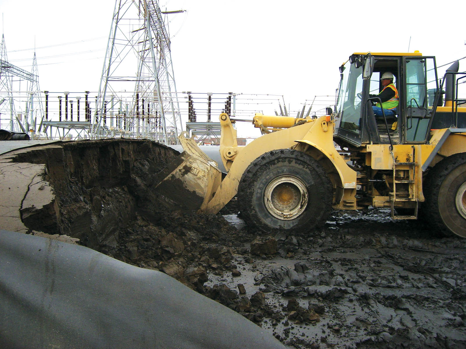
The dewatered CCR content could exceed 75% solids/25% water ratio by weight when coarse CCRs are involved, whereas finer, lighter material could reach a 50% solids/50% water ratio by weight upon consolidation. Once consolidated, the dewatered material can be excavated from the geotextile tubes for disposal (see Figure 5).
In typical applications, material is hydraulically pumped to geotextile tubes, where the wet volume is consolidated over time and the dewatered solids are disposed of. With beneficial-use applications, disposal is not required and the dewatered material may be used, which eliminates the need to landfill or incinerate. One option to avoid excavation and disposal of dewatered ash from geotextile tubes is land reclamation. Once the geotextile tubes are dewatered, the tubes become the final method of disposal and the dewatering cell can be capped, as shown in Figures 6a and 6b.
Another beneficial use application of CCR material can be building of containment structures using the geotextile tube as a construction form. The CCR material must have a nature that provides shear strength when dewatered. Typically, the material would be hydraulically dredged but also can be used transported to geotextile tubes in a paste form. No matter the method of filling, the geotextile tubes in their final dewatered form could be used to construct embankments, raise levees around an impoundment, or act as revetments. Filled geotextile containers can easily be installed to fit contours of a designated area.
Direct sluicing applications involving geotextile tubes provide an advantage to the coal-fired plants to minimize and eliminate CCR material from surface impoundments. In direct sluicing, the coal slurry is sluiced directly to geotextile tubes, where the CCRs are retained inside the tube and only effluent will be directed into the impoundments. Direct sluicing involves large volumes of ash slurry and requires a large area to construct the dewatering cell to house the geotextile tubes.
Typically, these applications have large flows, possibly over a 24-hour period, and this flow must be manifolded to multiple tubes to manage the
dewatering. As with typical dewatering applications involving geotextile tubes, bench testing must be conducted in the early stages of project development based on the nature of the flow sluiced from the power plant.
Due to the potential large volume of daily flows of a continuous operation, direct sluicing projects may require stacking of geotextile tubes to maximize the space you have to work with. If the laydown area for the dewatering cell is higher than low- to moderate-strength cohesive subgrades, an evaluation for bearing capacity and settlement should be conducted. The analyses enable the engineer to forecast any potential total settlement below the geotextile structures.
Conclusion
Coal-fired industrial by-products such as fly ash, bottom ash, slag, and FGD materials can be a real challenge for both small and large power facilities to remove and manage. With geotextile tube dewatering technology, facilities can easily consolidate waste materials across a wide spectrum of applications. With remediation and clean closure of surface impoundments, geotextile tube dewatering technology is an economical and sustainable water management option with many advantages, such as maintaining key water quality discharge parameters and sufficient freeboard for continuous operation. Another unique advantage of geotextile tube dewatering involves the ability to safely contain fly ash and prevent airborne particle contamination from windblown ash piles.
Geotextile tube technology can allow for beneficial use of consolidated ash residuals to reclaim land, create structures, use as road base, or increase the height of berms around an impoundment to increase its capacity. Reuse of these CCR materials preserves limited landfill space that would otherwise be consumed by normal disposal.
Direct sluicing into geotextile tubes allows coal-fired plants to retain CCR solids inside tubes while only sending effluent water into impoundments. This benefit from use of geotextile tubes greatly reduces, even essentially eliminating, the placement of CCR solids into surface impoundments.
Geotextile tubes are a flexible technology that provide high-volume, low-cost dewatering and containment. This technology offers an alternative to coal-fired plants for handling coal ash.
Christopher Timpson is Southeast engineering business manager with TenCate Geosynthetics.
REFERENCES
Fowler, J., Duke, M., Schmidt, M. L., Crabtree, B., Bagby, R. M., and Trainer, E. (2002). “Dewatering sewage sludge and hazardous sludge with geotextile tubes.” Proc., 7th Inter. Conf. on Geosynthetics, International Geosynthetics Society, Jupiter, Fla., 1007–1012.
Lawson, C. R. (2006). “Geotextile containment for hydraulic and environmental engineering.” Proc., 7th Inter. Conf. on Geosynthetics, International Geosynthetics Society, Jupiter, Fla., 9–48.
U.S. EPA. (2015). “Effluent limitations guidelines and standards for the steam electric power generating point source category,” 40 CFR Part 423, Federal Register 80 (212), Washington, D.C.
To put it quite simply old-fashioned ash ponds are a thing of the past. Geotextile tube dewatering enables a position where all kinds of beneficial use of the different coal wastes can be complicated.
Singapore built an artificial island using ash from waste. They were challenged but they did it.