 TEXTILES.ORG

Authors’ note: The conditions
This project started in central California in July 2014, and we watched the weather forecasts on the nightly news and we were calm. A few weeks later, the project is running longer than expected, and now we are watching the Weather Channel and reading Weather Underground and Accuweather with more interest than the sports and entertainment news.
We are starting to get antsy. In the weekly construction meetings, talking about the weather has stopped being small talk and has become the primary topic.
We are in California during a five-year drought and we are hoping for no rain. Are we bad? No! What is going on?
Our project includes a geosynthetic clay liner (GCL) and how it could become prematurely hydrated.
Innumerable owners, designers, construction quality assurance parties, installers, and material manufacturers have been in this situation before. However, based on the authors’ experience, a simple procedure to address prematurely hydrated GCL is not available in the literature. What follows is a case history of what the authors implemented.
Introduction
Installation of GCLs generally follows guidelines published by product manufacturers (e.g., Agru, CETCO, GSE, Huesker, Naue) and ASTM International (refer to ASTM D6102). The installation of GCLs is best overseen by construction quality assurance (CQA) personnel who follow CQA protocols or manuals established by designers. The CQA protocols are based on the installation guidelines published by product manufacturers and the experience of the designers.
Because installation of GCLs is weather-dependent, restrictions on deployment of GCLs during rainy weather are included in the CQA protocols. However, even with restricted deployment during rainy weather, GCL may still be affected by premature hydration due to unexpected events (e.g., an unexpected thunderstorm in the southwestern desert). While designers often assume some hydration of GCL will occur under load and account for this hydration in testing protocols such as direct shear testing (ASTM D6243), the main concern of premature hydration is for GCL in free swell situations where the GCL has begun to hydrate before being covered with the protective operations layer.
The typical procedure when GCL premature hydration is suspected is to remove the GCL panels and replace them with new panels. The product manufacturers guidelines discuss methods for assessing premature hydration; however, a concern arises on how to quantify or measure premature hydration in the field—that is, the GCL “looks hydrated” but are its properties compromised?
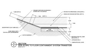
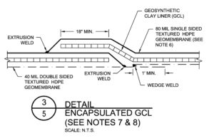
The case history described here involves construction of two composite liner systems at a municipal solid waste landfill located in central California. On the floor of the landfill, an encapsulated GCL (i.e., a double-nonwoven GCL between two welded double-sided textured geomembranes) was constructed above a compacted soil layer. On the sideslopes of the landfill, the liner system consisted of a double-nonwoven GCL above subgrade; the GCL was overlain by a single-sided textured geomembrane. Details for the liner systems are shown in Figures 1 and 2.
Construction of the liner system extended into the autumn of 2014 and was temporarily halted during the rainy season because windows of dry weather were not foreseen in the forecast. By the time of work stoppage (November 2014), the areas where the liner system had been constructed included a portion of the slope and a portion of the floor.
In December 2014, due to a series of storms, stormwater accumulated over a portion of the landfill.
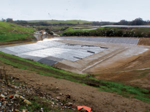
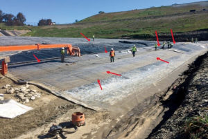
On the sideslope, the stormwater left a watermark on the high-density polyethylene (HDPE) geomembrane that had been deployed above the GCL. The accumulated stormwater reached approximately 10ft vertically from the toe of slope (i.e., the floor) and extended for a length of approximately 300ft along the lined slope (Figure 3). The owner surveyed the highest elevation of the watermark; the designer plotted the surveyed high water points (Figure 4).
In February to March 2015, as the weather improved, the owner, the design engineer, and the CQA consultant, with the help of the installer, evaluated the condition of the liner system that had been installed prior to the start of the rainy season.
Evaluation
The evaluation included two areas, labeled as Area A and Area B in Figure 4, where hydration of the GCL was suspected:
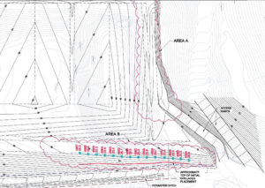
Area A: Floor area—encapsulated GCL
Area B: West sideslope area—GCL overlain by HDPE geomembrane
While Area A was encapsulated and the GCL should have remained unhydrated, a small leak was observed at the western edge of this area; it appeared that stormwater entered the encapsulated GCL through this leak.
Area B had been secured with sandbags and the HDPE geomembrane extended approximately 5ft beyond the limits of the GCL along the slope. Approximately 5ft of GCL were rolled up at the toe of slope and the HDPE geomembrane extended approximately 5ft past the toe.
Procedures
To evaluate the degree of hydration of the GCL in Area A and portions of Area B, the designer and the CQA firm first followed a visual procedure that was supplemented with laboratory testing.
The visual procedure consisted of walking the areas of concern and rolling back or cutting the top geomembrane to expose the deployed GCL below. Because of weather considerations (i.e., the possibility of spring rains), only an area that could be inspected and repaired in the same day was evaluated.
The evaluation of Area A (i.e., the floor with encapsulated GCL) consisted of:
Evaluating photographs of the area of liner that had been submerged.
Walking the area to detect soft zones that potentially indicated areas of hydrated GCL.
Cutting the top HDPE geomembrane.
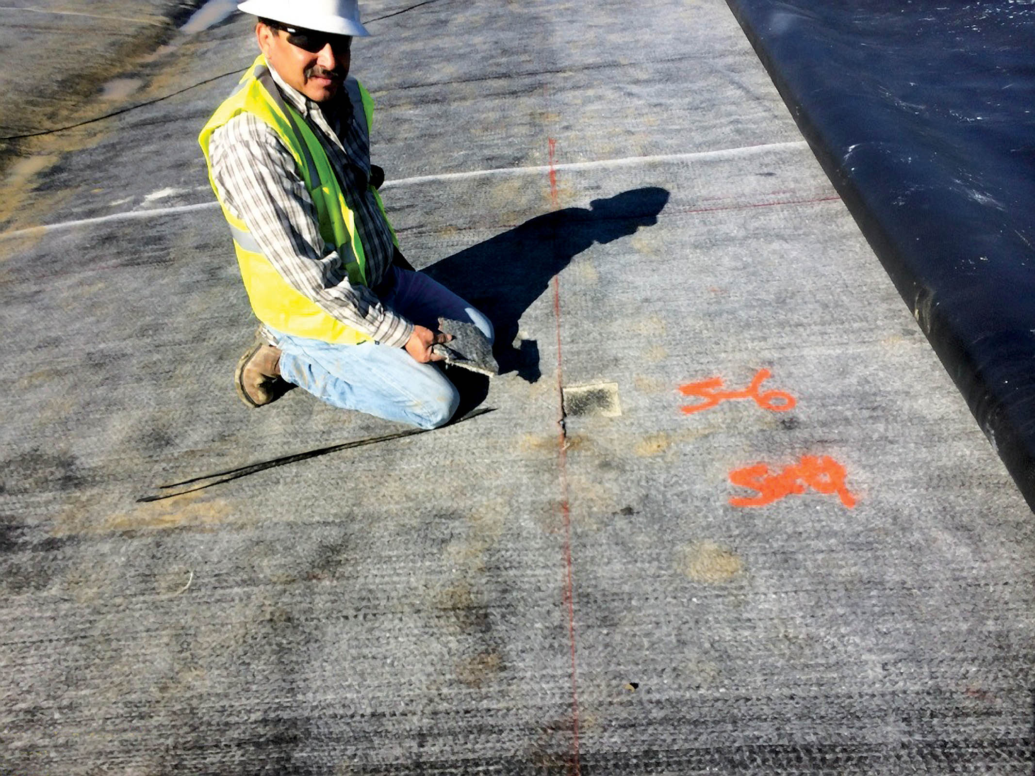
Inspecting the underlying GCL. As an initial measure of relative hydration, if a person’s footprint remained marked on a panel of GCL that had been deployed, hydration was suspected.
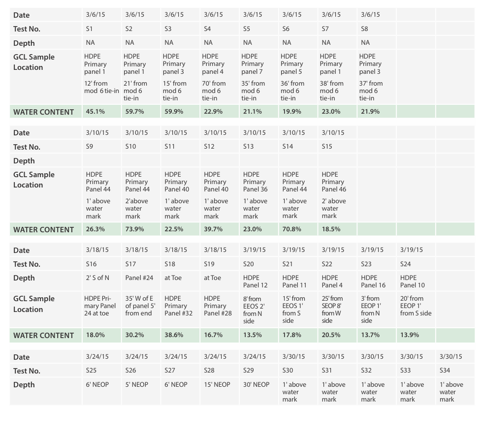
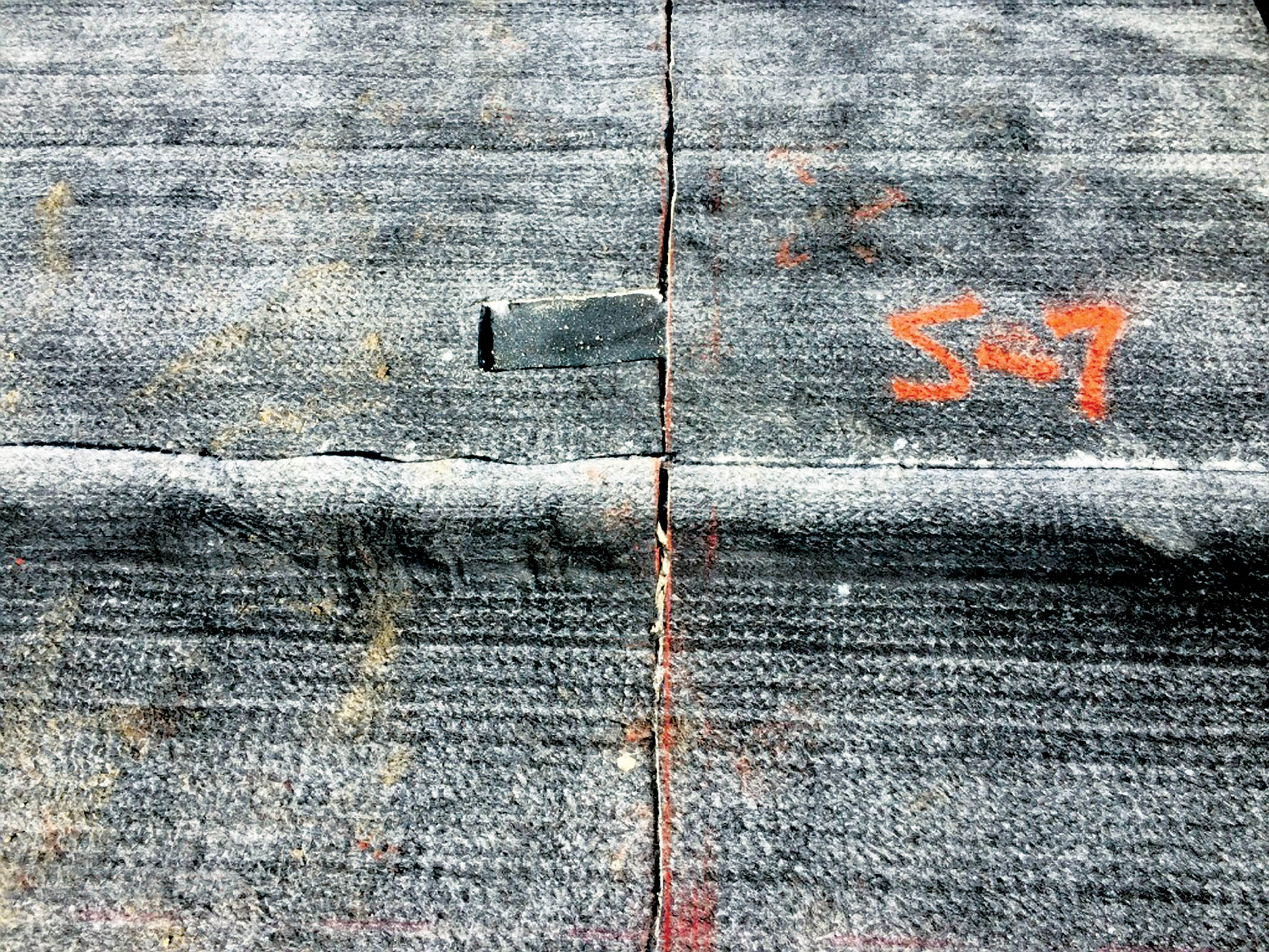
Delineating the hydrated GCL for replacement with new GCL. To delineate the area, samples of the GCL were cut. If the structure of the granular bentonite could not be discerned in the samples, the GCL was considered hydrated. The samples were tested for moisture content (ASTM D2216). The moisture content of the suspect GCL was compared to a background sample of installed GCL obtained from a non-submerged location. The background sample of GCL had a moisture content in the 20% range, whereas the hydrated GCL samples had moisture contents in the 50% range.
Figure 5 shows an overview of Area A. Samples S1, S2, S3, and S5 through S8 were collected in areas where premature hydration of GCL was suspected. Sample S4 was near a high point, in an area where no hydration of GCL was suspected. Table 1 tabulates the moisture contents of the GCL at the various locations.
Similar to Area A, the evaluation of Area B (west slope) consisted of:
Evaluating photographs of the area of liner that had been submerged and observing the high watermark left on the HDPE geomembrane.
The initial assessment of the GCL was to a level located approximately 11ft vertical above the floor. This height above the floor was selected because the maximum high watermark was surveyed approximately 10ft vertical above the floor (Figure 4); therefore, an additional 1ft vertical (approximately 3ft measured along the slope) was added for potential capillary rise of moisture within the GCL moving upslope. The HDPE geomembrane was cut and samples of GCL were obtained. The GCL samples evaluated above the high water line appeared unhydrated. GCL samples were also obtained below the high waterline. The samples collected below the highest waterline visually appeared to be hydrated.
Moisture content results confirmed that the GCL moisture content above the high waterline was in the 20% range, which was similar to the moisture content of the GCL when it was delivered. Moisture contents below the high waterline were in the 50% range.
At the temporary terminations, where sandbags were placed along the slope and stormwater flowing down the slope may have seeped in, the entire panel of GCL was removed and replaced.
Areas of the slope beyond the area where the high watermark was identified were inspected and found not hydrated.
As expected, the moisture contents of samples that were prematurely hydrated were significantly higher. Based on the assessment of the various moisture contents, GCL panels where replaced where high moisture contents were observed.
Repair procedure

Because Area A was on the floor and did not involve potential horizontal GCL seams on the slopes, hydrated GCL was removed and replaced and the HDPE geomembrane repaired in accordance with the specifications. A minimum 3ft overlap was used between the new and the existing GCL panels.
In Area B (i.e., the slope area), the hydrated portion of the GCL was cut 1ft beyond the limit of the hydrated area (measured along the slope), new GCL was deployed downslope, and a horizontal seam was constructed between the new GCL panel and the remaining GCL panel. We note that it is preferable not to have a horizontal seam in the GCL, but in certain situations it may be warranted. The remaining GCL panel was shingled over the new GCL so that a horizontal seam could be constructed. The horizontal seams were staggered 1ft between panels.
To construct the horizontal seam, a two-part process was followed. First, the installer produced a horizontal test seam following the procedures described below. The test seam was sent to a geosynthetics testing laboratory for testing so that the quality assurance (QA) of the horizontal seam could be assessed. To produce the test seam, the installer used an adhesive and on-site GCL to construct the seam; the CQA consultant documented the seaming process, packed the sample in a plastic bag, and shipped the sample for testing overnight.
After allowing the glue to cure for 48 hours from the time the seam was initially constructed, the testing laboratory conditioned the sample and performed wide-width tensile tests in accordance with ASTM D4595 and ASTM D4884. If the laboratory test results were deemed acceptable, the seaming procedure would be approved for the repair work (i.e., the second part of the process).
The test results were deemed acceptable, so the following procedure was used for each horizontal GCL seam:
The GCL panels were shingled so that the upslope (or upper) GCL panel is over the top of the downslope (or lower) GCL panel.
The upper GCL panel was overlapped over the lower GCL panel by 5ft.
The upper GCL panel was rolled back to expose the underside of the upper GCL panel.
The installer uniformly applied adhesive in the area between 6in. and 18in.(1ft wide) along the entire width of the upper GCL panel. That is, the area between 0in. and 6in. from the edge along the entire width of the upper GCL panel was left unglued. One can of adhesive was used for the entire width of the upper GCL panel.
Also, the installer uniformly applied adhesive in the area between 6in. and 18in. (1ft wide) along the entire width of the lower GCL panel. That is, the area between 0in. and 6in. from the edge along the entire width of the lower GCL panel was left unglued. One can of adhesive was used for entire width of the lower GCL panel.
On both panels, the adhesive was spread the entire width of the 1ft-wide area to cover the seam.
The upper GCL panel was laid on top of the lower GCL panel and both panels were pressed together by hand. The installer could use a roller to apply additional bonding pressure where adhesive was used.
The installer was also required to place bentonite on the lower GCL panel at a rate of 0.25 lb/ft between the downslope edge of the adhesive seam and the end of the upper GCL panel.
Last, at the exposed panel end, the geotextile backing of the upslope panel was heat bonded to the geotextile backing of the underlying GCL to help contain the bentonite placed along the panel end.
Conclusions and recommendations
Even though it is best to construct in dry weather and procedures to winterize or prepare liner construction for wet weather are in place as part of CQA, projects may run into wet periods where GCL becomes prematurely hydrated.
The case history presents a step-by-step procedure for assessing hydration of GCL that includes visual cues confirmed by laboratory procedures. Instead of relying only on visual cues, the procedures described allowed for assessment of premature hydration based on moisture content.
Here are two items for designers to consider including in the CQA procedures:
Request that during the project, CQA collect strips of the GCL rolls being deployed and save them. Samples need not be large; three 3-in. × 4-in. coupons in a plastic bag per roll would be sufficient. Why 3?—One for the designer/CQA, one for the installer, one as a backup. The samples would be labeled with date and panel number. If no weather issues arise, the samples can be discarded after the work is accepted by the owner. However, the samples will be invaluable to assess the GCL at the time of installation versus what appears to be prematurely hydrated.
Request that panel layouts for GCL be kept by the installer. It is typical for geomembrane panel layouts to be kept, showing destructive sample locations, etc. Panel layouts for GCL are useful to track areas of GCL, rolls sampled, hydrated areas, and subsequent repairs.
If not part of the formal CQA procedures, and if it looks like there is a possibility that the project will extend into the rainy season, the authors recommend the collection of GCL samples so that the state of the GCL at the time of installation is documented and available for comparative purposes.
Acknowledgments
The writers want to acknowledge the work of Messrs. Rogelio Armenta and Bryan Fritzler of Geo-Logic Associates (GLA), construction quality assurance (CQA) consultants for this project.
Fabrizio Settepani is a senior engineer with Geosyntec Consultants Inc.
Sangeeta Lewis is the owner, Lewis Engineering, based in Piedmont, Calif.
Kasey Kolassa is on the staff of the Santa Cruz County (Calif.) Department of Public Works.