 TEXTILES.ORG

Introduction
This case history focuses on the construction of a crucial thin rock layer over geosynthetics and the solution encountered during the first construction phase of an RCRA Subtitle C embankment cover system at a hazardous and radioactive disposal site. The top and 5:1 sideslopes of the cover system were constructed with a cap consisting of geosynthetics and native rock products. The process included the selection and testing of an appropriate geotextile and geomembrane system and the placement of a thin, 15.24cm- (6in.)-thick filter rock cover layer placed directly over the required geosynthetics followed by the placement of further rock layers. The construction of this 15.24cm filter rock layer was successfully addressed by the project team. This case history specifies how the contractors successfully placed this thin filter rock system using a portable conveyor device while protecting the geosynthetics.
1. Site overview
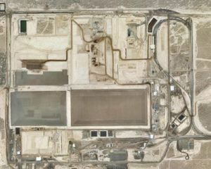
EnergySolutions is an international nuclear services company that operates a low-level radioactive and hazardous waste disposal site near Clive in Utah’s west desert (Clive Facility–Figure 1). The radioactive and hazardous waste is managed in five permitted partially buried landfills constructed using native rock and soil materials. Construction is governed by permitted CQA/QC plans. The MWE is located in the southeastern corner of the site and is Clive Facility’s only permitted hazardous and radioactive waste landfill.
2. Embankment overview
The MWE was permitted and construction began in 1991 (Envirocare, 1992). The embankment was designed to hold more than 917,000 cubic meters (1.2 million cubic yards) of radioactive and hazardous waste.
The MWE was originally designed and permitted with 20 cells numerically numbered from 1 to 10 each, with the western half labeled “A” and the eastern half labeled “B.” Each cell half is approximately 46m wide × 122m long (150ft × 400ft) with an RCRA-required 3ft-thick 1 × 10⁻⁷cm/sec compacted clay liner layer underlying three geosynthetically lined leak detection systems (EnergySolutions, 2003).
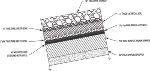
Following waste placement the MWE was covered by a native clay, rock, and geosynthetics system shown in Figure 2. The native clay system is a 30.48cm- (1ft)-thick temporary cover layer and a minimum 60.96cm- (2ft)-thick 5 × 10⁻⁸cm/sec radon barrier layer designed to contain the radon gas byproduct from the radioactive waste decay. The RCRA required geomembrane, a 60-mil textured double-sided HDPE liner, was placed over the radon barrier followed by a 12oz nonwoven geotextile placed for drainage and cushion. (EnergySolutions, 2003).
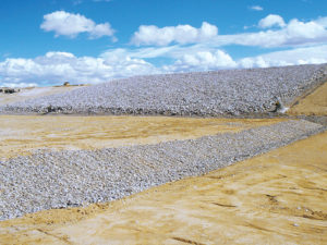
The permitted design then required a filter and erosion rock cover system atop the geosynthetic materials. The rock is composed of, in placement sequence, a minimum 15.24cm (6in.) of type-B filter rock, 30.48cm (1ft) of sacrificial soil, 15.24 cm (6in.) of type-A filter rock, and a final 45.72cm (1.5ft) of type-A riprap rock on the sideslope and 45.72cm (1.5ft) of type-B riprap rock on the top slope.
The top slope was designed to shed precipitation to a rock-lined, clay-based perimeter ditch that ultimately drains to an evaporation pond located on the perimeter of the Clive Facility.
The geomembrane and geotextile materials were selected and approved following direct shear testing performed by an independent testing firm. The CQA/QC manual required that direct shear testing be conducted at the interfaces between the radon barrier and the 60-mil HDPE geomembrane, between the 60-mil geomembrane and the nonwoven geotextile, and between the nonwoven geotextile and the type-B filter zone material prior to construction.
This direct shear testing consisted of four samples, with one on the low end, two in the middle, and one on the high end of the normal stress range. The geosynthetics system approved was required to have an interface friction angle greater than or equal to 16° and an adhesion/cohesion greater than or equal to 50psf. The geomembrane and geotextile selected met those requirements (Dutson, 2014).
3. Construction
In addition to the MWE specifications, the permit defined how much leakage in the leak detection systems is allowable.
In 2010, the MWE’s 3A cell began to show liquids accumulating above action levels within the middle and bottom pipes of the three-pipe leak detection system. This was not common. Many studies, including an excavation around the pipes, were undertaken and were inconclusive as to the source of the excessive leakage.
Following discussions with state officials, it was decided to proceed with the first phase of the permitted MWE cover system in an effort to cap the waste, minimize precipitation infiltration, and observe if the leakage rate decreased to allowable levels (McCandless, 2011).
After months of field preparation, which included placement of the temporary cover and releasing the surrounding area from potential radioactive contamination for “outside” construction access, construction on the MWE 2A (partial) and 3A cells began in the summer of 2012. The corner 1A cell was not ready for construction at that time and was not included in that scope of cover work. Construction included material preparation of the radon barrier and the rock cover products. The radon barrier clay material was mined from an adjacent county section to the Clive Facility, mixed with a deflocculant (i.e., sodium tripolyphosphate), and moisture conditioned per CQA/QC requirements to maximize the ability to achieve the low permeability clay.
The rock products were mined from a pit located about 32km (20mi) north of the Clive Facility, hauled to the site, and screened to create the five rock products. Following material preparation, the contractor prepared a required test pad designed to prove that the placement method (i.e., four passes of a compactor and two passes of a “partially loaded” articulating dump truck at “struck” capacity) of radon barrier would achieve the required compaction (i.e., 95% of a Standard Proctor) and permeability (i.e., 5 × 10⁻⁸cm/sec) within the required moisture window (i.e., optimum to 5% over optimum).
The HDPE-T (textured) geomembrane and nonwoven geotextile were ordered, delivered, and approved by the QA contractor during this period of the project. Placement of more than 9,170 cubic meters (12,000 cubic yards) of radon barrier, 10,033 square meters (12,000 square yards) each of the HDPE-T geomembrane and the nonwoven geotextile, and approximately 7,430–9,100 square meters (80,000–98,000 square feet) of each of the rock products at their respective layer thicknesses was performed beginning in the summer of 2012, concluding in the summer of 2013 due to issues during radon barrier placement, weather delays, and a contractual dispute with the contractor that was resolved.
The radon barrier work included remediation of an exposed 2012 radon barrier that had desiccated and cracked and that was successfully rehydrated in early summer 2013 so the cover of the 3A and 2A cells could be completed during the 2013 construction season (Dutson, 2014).
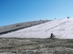
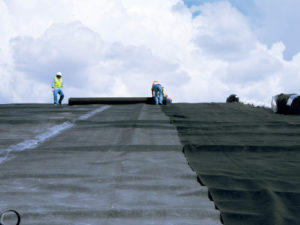
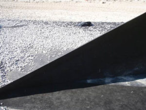
After completion of the radon barrier and near perfection of the top of the radon barrier clay surface, the geosynthetics contractors (i.e., 3A in 2012 and 2A in 2013) placed the textured HDPE over the clay followed by the nonwoven geotextile (see Figures 3 and 4).
4. Type-B filter rock placement
From the outset, a critical issue with the MWE’s cover design was the placement of the minimum 15.24cm- (6in.)-thick type-B filter zone directly atop the geomembrane and geotextile. The B filter is a 3.8-cm (1.5-in.) minus rock product required to meet specific permitted gradation ratios to the sacrificial soil.
According to national industry standards, the minimum placement uncompacted thickness under a low ground pressure piece of equipment (such as the D6RLGP bulldozer used on this project) is 30.48cm (12in.) and the minimum thickness under rubber-tired equipment, such as a haul truck, is 0.9m (36in.) (Thiel, 2011).
While the B filter specification was provided with a minimum thickness and placement to a 30.48cm (12in.) thickness was considered, the screening production of the B filter product during 2012 was time consuming and took the better part of the spring months allotted prior to placement. Therefore, due to cost and schedule, the owner decided to produce only what was needed for the project scope and to hold to the minimum 15.24cm thickness.
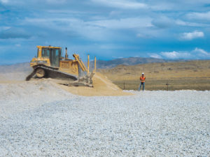
The B filter 15.24cm (6in.) thickness placement challenge was given to the contractor with a charge to propose a placement solution. The solution proposed and then successfully executed in 2012 on the 3A cell and in 2013 on the 2A cell involved a portable conveyor system that could accurately place the small rock to the design thickness at more than 21m (70ft) away while navigating the 5:1 slope and the distances.
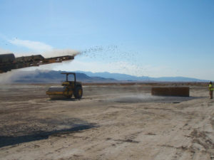
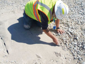
The portable conveyor was tested in September 2012 during a demonstration prior to B filter placement to verify that the conveyed distance and placement method would not cause the B filter to go out of gradation specification (see Figure 5). The demonstration included using the portable conveyor to launch the B filter material onto a sample of the project HDPE-T geomembrane and the nonwoven geotextile from a distance comparable to the farthest distance of field placement after which the geosynthetics were inspected for damage and a sample of the placed B Filter was tested for gradation compliance (see Figures 12 and 13).
Inspection and gradation results showed that the conveyor process delivered the B filter material to the 15cm thickness without damaging the geosynthetics or rendering the B filter material out of gradation specification. Thus the portable conveyor allowed the B filter material to be placed to the permitted thickness without the risk of puncturing or tearing the geosynthetics and damaging the underlying radon barrier as heavy equipment might have done on the thin lift.
In like manner, a demonstration the same day was conducted to inspect the geosynthetics for damage following placement of a 30.48cm (12in.) thickness of sacrificial soil over the 15.24cm- (6in.)-thick B filter and project geosynthetics. Inspection showed that the 30.48-cm (12-in.) thickness and dozer placement method did not compromise the geosynthetics (Dutson, 2014).
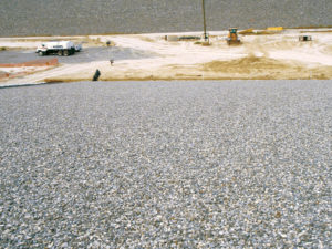
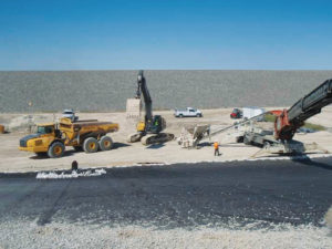
B filter placement began following the 2012 demonstrations. Approximately 1,370 cubic meters (1,800 cubic yards) of B filter was placed over the constructed HDPE-T geomembrane and the nonwoven geotextile in the 15.24-cm (6-in.) thickness using the portable conveyor system.
In 2012, the conveyor was loaded by two loaders for the 3A cell from a stockpile located at the toe of the slope, In 2013, the conveyor was loaded by a trackhoe and haul trucks for the 2A cell. The contractor temporarily overbuilt the sacrificial soil to create the minimum required 0.9m- (36in.)-thick haul road for the conveyor, the loaders, trackhoe, and haul trucks.
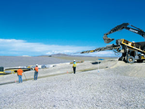
The conveyor operator placed the rock to thickness using marked orange cones moved by hand as needed. The contractor’s workers fed the conveyor and performed minimal hand raking and the entire operation for each cell took less than three days each per cell to complete—an enormous cost and time success.
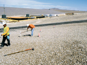
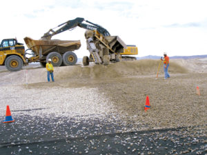
Quality control observed the placement using grade stakes, as required by the CQA/QC plan, and also movable orange cones (see Figures 6 and 8) so as not to damage the geosynthetics or the radon barrier. Care was taken to protect the underlying geosynthetics and radon barrier surfaces and the type-B filter zone material was handled in such a manner to prevent contamination from waste material and segregation of finer materials.
QC observed placement of the type-B filter zone material to ensure that soil fines were not concentrated in localized areas. Where type-B filter zone soil fines were concentrated in localized areas, the project manager was directed by QC to evenly distribute the fines or remove them and the fines were subsequently distributed (Dutson, 2014)—see Figures 6–9.
Other important insights from the B filter placement operation include that the 2012 B filter hauling operation by loaders was replaced in 2013 by the trackhoe and haul trucks by the contractor to minimize spillage and increase speed of placement. While spillage on the sacrificial soil was easily cleaned, the contractor found that, due to access issues, hauling B filter over the unfinished radon barrier in 2012 was less productive when they had to hand remove rocks from the radon barrier because of tight CQA/QC specifications.
A 2013 sacrificial haul road over the temporary cover interface between the 1A and 2A cells for B filter placement on the 2A cell became a headache to remove for the next phase of cover placement, under way at the time of writing this paper.
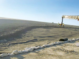
Finally, the placement scheme for the B filter was carried out by first placing the B filter at the sideslope/top slope breakover to help chase geomembrane wrinkles toward all sandbagged edges and the permit-required anchor trench at the base of the embankment. The contractor then moved along the top slope to the edges and then in like manner down the sideslope from the top slope toward the edges.
The end product was successful placement without HDPE wrinkles or tearing issues.
The sacrificial soil was used to create the haul roads and access roads for the conveyor as needed for reach of the B filter. Following B filter placement the sacrificial soil was pushed out to the 30.48-cm (12-in.) thickness by keeping the LGP bulldozer on the 30cm-thick lift and off of the B filter as shown in Figure 10.
QC, QA, and at least one worker from the contractor observed placement of the B filter and sacrificial soil to ensure that the contractor minimized the starting, stopping, and turning of the dozer to protect the underlying geosynthetic materials. Geomembrane wrinkles were successfully managed by this placement method. The ground observers watched for wrinkling and walked out or assisted with limiting the wrinkling as the B filter was placed on the geosynthetics. As a result of these efforts, no wrinkles folded over and no cutting or repair was required.
5. Conclusion
The MWE 3A and 2A cells were successfully completed and the placement of the thin, 15.24cm (6in.), type-B filter zone over the HDPE-T geomembrane and the nonwoven geotextile was performed using a portable conveyor device. The contractor used the sacrificial soil to maneuver the equipment over the placed type-B filter and operated carefully to protect the geosynthetics.
The remaining rock layers were successfully placed and the cover project was completed under budget. The completed project is shown in Figure 11.
Garrett Dutson, M.ASCE, P.E., EnergySolutions Inc., USA, gdutson@energysolutions.com. All photos courtesy of EnergySolutions
References
Dutson, Garrett Q., (2014). Mixed Waste Phase 1 Cover (Cells 2A & 3A) Construction Certification Report and As-Built Drawings, EnergySolutions Inc., Salt Lake City, Utah: 1–15 and Attachments.
EnergySolutions (2003). State-Issued Part B Permit, issued by Utah Department of Environmental Quality, Salt Lake City, Utah: Module V.
McCandless, Sean, (2011). Letter from EnergySolutions Inc. to Utah Solid and Hazardous Waste Control Board, October 5, 2011: CD11-0272.
Thiel, Richard, (2011). Design and Construction of Waste Containment Systems, Thiel Engineering, Geo-Frontiers 2011, Dallas, Texas: p. 28.